thermastor Phoenix FireBird Fury User manual

1
WWW5SE0HOENIXCOM s SALES 5SE0HOENIXCOM4OLL&REE
Phoenix FireBird Fury
PN 4030480
Owner’s Manual — Phoenix FireBird Fury
)NSTALLATION /PERATION AND 3ERVICE )NSTRUCTIONS
Important Instructions – Read and Save These Instructions
The FireBird Fury portable electric heater features multiple power receptacles for connection to common 120VAC outlets,
240VAC range/dryer type outlets, or both. The Fury can output up to 62,000 BTU’s of clean, safe heat at 750 CFM. The
Fury’s remote thermostat provides a means to control the temperature in the drying chamber, while its internal temperature
cutout ensures safe operation.
4HE 0HOENIX &IRE"IRD &URY
s ,ISTED BY %4, TO 5, 3AFETY 3TANDARDS .%#
#OMPLIANT
s !MP /PERATION AT 6!# "45
"45
s !MP /PERATION AT 6!# UP TO INDEPENDENT
CIRCUITS "45
s 4WO 0OWER #ORDS DRYER RANGE INCLUDED
s 2EMOTE 4HERMOSTAT WITH CONNECTING WIRE
INCLUDED
s 3TANDARD -%26 AIR lLTER INCLUDED
s -ULTIPLE DUCTING OPTIONS
s v )NLET v /UTLET
s 3TAINLESS 3TEEL #ABINET
Specifications subject to change without notice.
TS-670
08/11
,IEN 2D s -ADISON 7)

2
WWW5SE0HOENIXCOM s SALES 5SE0HOENIXCOM4OLL&REE
4ABLE OF #ONTENTS
Introduction ................................................................1
1. Specifications........................................................
2. Operation .............................................................
2.1 Transporting ...................................................
2.2 Electrical Requirements ..................................
$UCTING...........................................................
2.4 Control Panel .................................................
2.5 Hour Meter ....................................................4
2.6 Remote Thermostat Connection ......................4
3. Maintenance.........................................................4
!IR &ILTER .........................................................4
4. Service ................................................................4
4ECHNICAL $ESCRIPTION ......................................4
4.2 Troubleshooting ..............................................4
5. Options and Accessories .......................................5
6. Wiring Diagram ....................................................6
7. Service Parts .......................................................7
Warranty ..............................................................8
Serial No. ___________________________
0URCHASE $ATE ?????????????????
$EALERS .AME ???????????????????????????????????
s 5NIT )NTENDED FOR ).$//2 53% /.,9 $/ ./4 53% /54-
$//23
s $EVICE IS (/4 WHEN IN USE 4O PREVENT BURNS AVOID SKIN
contact with hot surfaces.
s 5SE HANDLE WHEN MOVING DEVICE
s -AINTAIN v MINIMUM CLEARANCE BETWEEN DEVICE OUTLET
and any combustible materials such as furniture, pillows,
bedding, papers, clothes and curtains. Keep such items
away from sides and rear of device.
s %XTREME CAUTION IS NECESSARY WHEN DEVICE IS USED BY
or near children or invalids and whenever device is left
operating unattended.
s !LWAYS UNPLUG UNIT WHEN NOT IN USE
s $/ ./4 /0%2!4% WITH DAMAGED CORD PLUG OR AFTER UNIT
malfunctions, has been dropped or damaged in any man-
ner. Return to authorized service facility for adjustment
or repair.
s $EVICE NOT INTENDED FOR USE DIRECTLY IN AN AREA WHERE IT
may fall into a bathtub or other water container.
s $/ ./4 RUN CORD UNDER CARPETING OR OTHER mOOR COVERING
Arrange cord away from traffic area and where it will not
be tripped over.
s4O DISCONNECT DEVICE TURN CONTROLS OFF THEN REMOVE PLUG
from outlet.
s #ONNECT /.,9 TO PROPERLY GROUNDED OUTLETS
s $/ ./4 INSERT OR ALLOW FOREIGN OBJECTS TO ENTER ANY
VENTILATION OR EXHAUST OPENINGS AS THIS MAY CAUSE AN
%,%#42)# 3(/#+ OR &)2% OR DAMAGE THE HEATER
s4O PREVENT A POSSIBLE lRE DO NOT BLOCK AIR INTAKES OR EX-
HAUST IN ANY MANNER $O NOT USE ON SOFT SURFACES LIKE A
BED WHERE OPENINGS MAY BECOME BLOCKED
s $EVICE HAS HOT AND ARCING OR SPARKING PARTS INSIDE $O
NOT USE IN AREAS WHERE GASOLINE PAINT OR mAMMABLE
liquids are used or stored.
s 5SE DEVICE ONLY AS DESCRIBED IN THIS MANUAL !NY OTHER
use not recommended by the manufacturer may cause
lRE ELECTRIC SHOCK OR INJURY TO PERSONS
s !VOID USE OF AN EXTENSION CORD FOR 6 SERVICE BE-
CAUSE THE EXTENSION CORD MAY OVERHEAT AND CAUSE A
RISK OF lRE (OWEVER IF AN EXTENSION CORD IS REQUIRED
THE CORD SHALL BE .O !7' MINIMUM SIZE AND RATED
NOT LESS THAN 7ATTS #ORDS USED FOR 6 SERVICE
SHALL BE .O !7' MINIMUM SIZE RATED NOT LESS THAN
7ATTS
Read the operation and maintenance instructions
carefully before using this unit. Proper adherence to these
instructions is essential to obtain maximum benefit from
your Phoenix FireBird Fury.

WWW5SE0HOENIXCOM s SALES 5SE0HOENIXCOM4OLL&REE
3PECIlCATIONS
0ART .O
0OWER Blower Circuit: 2 Amp at 120VAC 60Hz, 1
Phase
220/240VAC 60Hz, 1 Phase Heater Circuit:
5SER 3ELECTABLE !MP /PERATION
!MP & TEMPERATURE RISE "45
!MP & TEMPERATURE RISE "45
120VAC 60Hz, 1 Phase Heater Circuits (up to
6):
!MP CIRCUIT & TEMPERATURE RISE
circuit: 5,000 BTU
-AXIMUM (EAT
"45 WITH & 4EMPERATURE 2ISE AT
750CFM
"LOWER 750 CFM
&ILTERS Pleated Media MERV-11
$UCT /PTIONS )NLET n v &LEX$UCT
/UTLET n v &LEX$UCT
7ARRANTY 1 year 100% of Parts and Labor
Dimensions
Unit Shipping
7IDTH v v
(EIGHT v v
$EPTH v v
7EIGHT LB LB
/PERATION
4RANSPORTING
4HE 0HOENIX &IRE"IRD &URY MUST ALWAYS BE UPRIGHT WHEN
TRANSPORTED BY VEHICLE )T MAY BE TIPPED ONTO ITS HANDLE
AND BACK FOR LOADING AND MOVING BY HAND 4HE 0HOENIX
&IRE"IRD &URY FEATURES A HIGHIMPACT PLASTIC SKID PLATE
which protects the unit while navigating obstacles such as
curbs, stairways, and while loading into vehicles.
%LECTRICAL 2EQUIREMENTS
4HE 0HOENIX &IRE"IRD &URY REQUIRES A 6!# OUTLET TO
power the onboard blower and control circuit. Heating
elements are separately powered by additional cords and
receptacles.
For the 240VAC heating elements, the FireBird Fury is
lTTED WITH A 6!# GROUNDED RECEPTACLE 7HEN USED
with the appropriate cord, it provides a ground connection
through the cord to the heater to protect the operator from
ELECTRIC SHOCK 4HE 0HOENIX &IRE"IRD &URY COMES EQUIPPED
with two 8’ long cords for connection to grounded
residential range and dryer receptacles. These cords have
plugs as shown. Note that no adapters are available for
these blade configurations, and none should be used.
120VAC heating elements each require cord connection
TO APPROPRIATE RECEPTACLES RATED AT ! OR MORE /NE
cord and receptacle are required per heating element.
Power cords should be appropriately sized (typically #12
minimum). Each heater cord should have a three-blade
grounding-type plug as shown. An adapter is available for
connecting to two-slot receptacles. The green grounding
LUG EXTENDING FROM THE ADAPTER MUST BE CONNECTED TO A
PERMANENT GROUND SUCH AS A PROPERLY GROUNDED OUTLET BOX
The adapter should not be used if a three-slot grounded
receptacle is available.
$UCTING
4HE 0HOENIX &IRE"IRD &URY CAN BE DUCTED AT THE INLET THE
outlet or both. The FireBird Fury lid and outlet adapter
ARE DESIGNED TO ACCOMMODATE v mEXIBLE DUCT 7HEN
SELECTING mEXIBLE DUCTING KEEP IN MIND ANTICIPATED OUTLET
temperatures. Air temperature increase is typically 50
TO DEGREES & !DDING DUCTING DECREASES AIRmOW WHICH
can increase outlet temperatures by up to 40 additional
degrees F.
NEMA 14-50.%-!
'ROUNDING 0IN
Plug Adapter /UTLET
'ROUNDING
Means
Metal
Screw

#ONTROL 0ANEL
Master Power Switch: The Master Power Switch located on
the left side of the control panel can be used to turn the
UNIT /. /&& OR SET THE UNIT TO BE CONTROLLED BY AN EXTERNAL
thermostat.
7HEN SET TO /. THE &URY WILL ENERGIZE THE BLOWER AND
CLOSE THE HEATER CONTACTORS CONTINUOUSLY $EPENDING ON
the connected power sources, the corresponding heater
ELEMENTS WILL BE ENERGIZED )N THIS MODE THE &URY IS
LIMITED TO & INCOMING AIR TEMPERATURE BY AN INTERNAL
thermostat.
7HEN SET TO 4(%2-/34!4 THE BLOWER WILL RUN CONTINUOUSLY
but the heating contactors will only energize when the
thermostat terminals (located under the lid) are connected
by a switch, remote thermostat, timer, etc.
Heat ON/OFF Switches: These switches individually
CONTROL THE 6!#7 HEATING ELEMENTS %ACH
switch connects and disconnects the power from the
receptacle below it. These switches are lighted to indicate
when power is connected and the corresponding heating
element is on.
(OUR -ETER
The digital hour meter measures the cumulative time that
THE UNIT IS TURNED ON TO TENTHS OF AN HOUR )T STORES AND
DISPLAYS THE TOTAL WHEN THE UNIT IS UNPLUGGED )T RESETS TO
zero after 99,999.9 hours of operation.
2EMOTE 4HERMOSTAT #ONNECTION
To connect the included remote thermostat, first locate
the thermostat terminals under the lid of the FireBird Fury.
There are 2 spring loaded terminals for connecting the
THERMOSTAT WIRING #ONNECT ONE WIRE TO EACH TERMINAL )F
the FireBird Fury is placed inside the space to be heated,
place the thermostat on top of the unit. For applications
where the FireBird Fury is placed outside the space to be
heated (e.g. ducting heat into a chamber), the 25’ cord
allows you to place the thermostat inside the heated
space.
)N ADDITION TO THE INCLUDED THERMOSTAT ANY DRYCONTACT
switch or other type of control that connects the terminals
together will cause the heating elements to run. The
4
WWW5SE0HOENIXCOM s SALES 5SE0HOENIXCOM4OLL&REE
THERMOSTAT CIRCUIT IS LOW VOLTAGE 6!# $/ ./4
#/..%#4 0/7%2 4/ 4(% 4(%2-/34!4 4%2-).!,3
Always press terminal levers to release spring pressure
before disconnecting thermostat wiring. Failure to do so
WILL LEAD TO EXCESSIVE WEAR ON SPRING LOADED TERMINAL
connector.
-AINTENANCE
!IR &ILTER
4HE 0HOENIX &IRE"IRD &URY IS EQUIPPED WITH A PLEATED FABRIC
AIR lLTER THAT MUST BE CHECKED REGULARLY 4HE STANDARD
lLTER IS A -%26 HIGH EFlCIENCY lLTER /PERATING THE
FireBird Fury with a dirty or obstructed filter will reduce
AIRmOW EVENTUALLY CAUSING THE HEATING ELEMENT TO SHUT
OFF )NSTALLING A CLEAN lLTER OR REMOVING THE OBSTRUCTION TO
RESTORE AIRmOW WILL ALLOW THE HEATING ELEMENT TO OPERATE
again.
The filter can generally be vacuumed clean several times
before needing replacement. Replacement filters can be
ordered from the factory or purchased locally if available.
WARNING: DO NOT operate the unit without the filter or
with a less effective filter as the heating coils inside the
unit could become clogged and require disassembly to
clean.
3ERVICE
WARNING: Servicing the Phoenix FireBird Fury with its
high voltage circuitry presents a health hazard which
could result in death, serious bodily injury, and/or property
damage. Only qualified service people should service this
unit.
Do not operate the unit without the front panel in place.
High voltage is present, heater burnout may result.
4ECHNICAL $ESCRIPTION
4HE 0HOENIX &IRE"IRD &URY USES A WOUND NICHROME HEATING
element to provide multiple heat settings depending on
application requirements or available power. The heating
elements are operated by a 24VAC control circuit and a
number of relays and contactors. For safety, there is an
air pressure switch that will shut the heating elements off
OR PREVENT THE HEATING ELEMENTS FROM COMING ON IF AIRmOW
is restricted at either the inlet or the outlet. An additional
safety switch limits the incoming air temperature to
APPROXMIATELY & 4HIS SWITCH SHUTS OFF THE HEATING
elements and automatically resets when the temperature
FALLS TO APPROXIMATELY &

5
WWW5SE0HOENIXCOM s SALES 5SE0HOENIXCOM4OLL&REE
Specifications subject to change without notice.
4ROUBLESHOOTING
NOTE: High Power setting requires an external 50A circuit.
Connecting to a 30A circuit with unit set to High Power will
result in an external circuit breaker trip. Low voltage heating
circuits require dedicated 15A minimum service for each circuit
(up to 6 total).
Blower not running
1. Unit unplugged, no power to outlet
2. 0OWER 3WITCH NOT WORKING
7IRING FAULT INSIDE DEVICE
4. $EFECTIVE BLOWER OR BLOWER CAPACITOR
Blower running but no heat
1. 0OWER SWITCH IS SET TO h4HERMOSTATv AND NO THERMOSTAT IS
connected, or thermostat is open
2. 6!# 4RANSFORMER CIRCUIT BREAKER IS TRIPPED
!IRmOW RESTRICTED AT INLET OR OUTLET
4. (IGH TEMPERATURE LIMIT REACHED &
5. Heating contactor(s) not operating
6. 7IRING FAULT INSIDE DEVICE
7. $EFECTIVE HEATING ELEMENT PRESSURE SWITCH OR
temperature limit switch
/PTIONS AND !CCESSORIES
v X )NTAKE &LEX $UCT
v X v X v 0LEATED -EDIA -%26
v X v X v 3TANDARD 0LEATED -EDIA -%26
6 #ORD +IT
6 #ORD +IT
6 #ORD +IT
6 #ORD +IT
6 #ORD +IT
2EED ,- -ULTI&UNCTION -ETER

6
WWW5SE0HOENIXCOM s SALES 5SE0HOENIXCOM4OLL&REE
7IRING $IAGRAM
L1 L2
240 VAC
60HZ, 1 PH
L1 N
1500 W ELEMENT
(9.3 OHMS)
120 VAC
60HZ, 1 PH
CONTACTOR
#3 & #4
X6 TOTAL CIRCUITS
2880 W ELEMENT
(19.4 OHMS)
CONTACTOR #2
3840 W ELEMENT
(14.5 OHMS)
CONTACTOR #1
2880 W ELEMENT
(19.4 OHMS)
L1 L2
120 VAC
60HZ, 1 PH
CONTACTOR COIL # 3
CONTACTOR COIL # 2
CONTACTOR COIL # 1
HI /LOW
POWER
SWITC H
140°
THERMAL
CUT-OUT
PRESSURE
SWITC H
OPTIONAL
THERMOSTAT
MASTER
POWER
SWITC H BLOWER
BROW N
BLAC K
HOUR
METER
TRANSFORMER
24V
BLUE
CONTACTOR COIL # 4
4030942b
15 mf
7
WWWUSEPHOENIXCOM s SALES THERMASTORCOM4OLL&REE
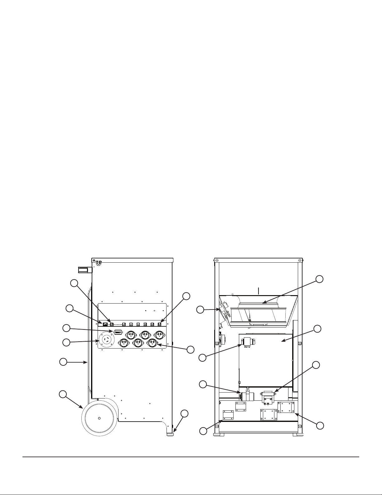
3ERVICE 0ARTS
Item Description QTY Part No.
(EAT ()'(,/7 3WITCH
-ASTER 0OWER 3WITCH
(OUR -ETER
&LANGED ! )NLET
3KIDPLATE
7HEEL
&OOT
&LANGED 6 )NLET
(EAT /./&& 3WITCHES
10 Pressure Switch 1 4029187
4HERMOSTAT
MF #APACITOR
3INGLE 0OLE #ONTACTOR
0OLE #ONTACTOR
6!# 4RANSFORMER
16 Heating Elements
7
7
7
17 Blower 1 4029455
1
2
4
5
6
7
8
9
10
11
12
17
16
15
14

0HOENIX &IRE"IRD &URY ,IMITED 7ARRANTY
Warrantor:
Therma-Stor LLC
4201 Lien Rd
-ADISON 7)
4ELEPHONE
Who Is Covered: 4HIS WARRANTY EXTENDS ONLY TO THE ORIGINAL ENDUSER OF THE 0HOENIX &IRE"IRD &URY AND
may not be assigned or transferred.
Year One: 4HERMA3TOR ,,# WARRANTS THAT FOR ONE YEAR THE 0HOENIX &IRE"IRD &URY WILL OPERATE
FREE FROM ANY DEFECTS IN MATERIALS AND WORKMANSHIP OR 4HERMA3TOR ,,# WILL AT ITS OPTION REPAIR OR
replace the defective part(s), free of any charge.
End-User Responsibilities: 7ARRANTY SERVICE MUST BE PERFORMED BY A 3ERVICER AUTHORIZED BY
4HERMA3TOR ,,# )F THE ENDUSER IS UNABLE TO LOCATE OR OBTAIN WARRANTY SERVICE FROM AN AUTHORIZED
3ERVICER HE SHOULD CALL 4HERMA3TOR ,,# AT THE ABOVE NUMBER AND ASK FOR THE 4HERMA3TOR
3ERVICE $EPARTMENT WHICH WILL THEN ARRANGE FOR COVERED WARRANTY SERVICE 7ARRANTY SERVICE WILL BE
PERFORMED DURING NORMAL WORKING HOURS
The end-user must present proof of purchase (lease) upon request, by use of the warranty card or
other reasonable and reliable means. The enduser is responsible for normal care. This warranty
DOES NOT COVER ANY DEFECT MALFUNCTION ETC RESULTING FROM MISUSE ABUSE LACK OF NORMAL CARE
corrosion, tampering, modification, unauthorized or improper repair or installation, accident, acts of
nature or any other cause beyond Therma-Stor LLC’s reasonable control.
Limitation and Exclusions: )F ANY 0HOENIX &IRE"IRD &URY PART IS REPAIRED OR REPLACED THE NEW PART
shall be warranted for only the remainder of the original warranty period applicable thereto (but all
WARRANTY PERIODS WILL BE EXTENDED BY THE PERIOD OF TIME IF ANY THAT THE 0HOENIX &IRE"IRD &URY IS OUT
of service while awaiting covered warranty service).
50/. 4(% %80)2!4)/. /& 4(% 72)44%. 7!22!.49 !00,)#!",% 4/ 4(% 0(/%.)8 &IRE"IRD &URY /2
!.9 0!24 4(%2%/& !,, /4(%2 7!22!.4)%3 )-0,)%$ "9 ,!7 ).#,5$).' -%2#(!.4!"),)49 !.$
&)4.%33 &/2 ! 0!24)#5,!2 0520/3% 3(!,, !,3/ %80)2%
!,, 7!22!.4)%3 -!$% "9 4(%2-!34/2 ,,# !2% 3%4 &/24( (%2%). !.$ ./ #,!)- -!9 "%
-!$% !'!).34 4(%2-!34/2 ,,# "!3%$ /. !.9 /2!, 7!22!.49 ). ./ %6%.4 3(!,, 4(%2-!
34/2 ,,# ). #/..%#4)/. 7)4( 4(% 3!,% ).34!,,!4)/. 53% 2%0!)2 /2 2%0,!#%-%.4 /& !.9
0(/%.)8 &IRE"IRD &URY /2 0!24 4(%2%/& "% ,)!",% 5.$%2 !.9 ,%'!, 4(%/29 &/2 !.9 30%#)!,
).$)2%#4 /2 #/.3%15%.4)!, $!-!'%3 ).#,5$).' 7)4(/54 ,)-)4!4)/. 7!4%2 $!-!'% 4(%
%.$53%2 3(/5,$ 4!+% 02%#!54)/.3 !'!).34 3!-% ,/34 02/&)43 $%,!9 /2 ,/33 /& 53%
/2 $!-!'% 4/ !.9 2%!, /2 0%23/.!, 02/0%249
Some states do not allow limitations on how long an implied warranty lasts, and some do not
ALLOW THE EXCLUSION OR LIMITATION OF INCIDENTAL OR CONSEQUENTIAL DAMAGES SO ONE OR BOTH OF THESE
limitation may not apply to you.
Legal Rights: This warranty gives you specific legal rights, and you may also have other rights which
vary from state to state.
8
WWW5SE0HOENIXCOM s SALES 5SE0HOENIXCOM4OLL&REE
Other thermastor Electric Heater manuals

Popular Electric Heater manuals by other brands


Austria Email
Austria Email EBH-KDW Operating and mounting instructions

DEVOLA
DEVOLA DVPW1000B instruction manual

Euromate
Euromate 482174 Original instructions

Intertec Data Systems
Intertec Data Systems CP MULTITHERM DG.A HI operating instructions

Goldair
Goldair GEOR260 operating instructions

Global Industrial
Global Industrial 246100 user manual


