Austria Email EBH-KDW Service manual
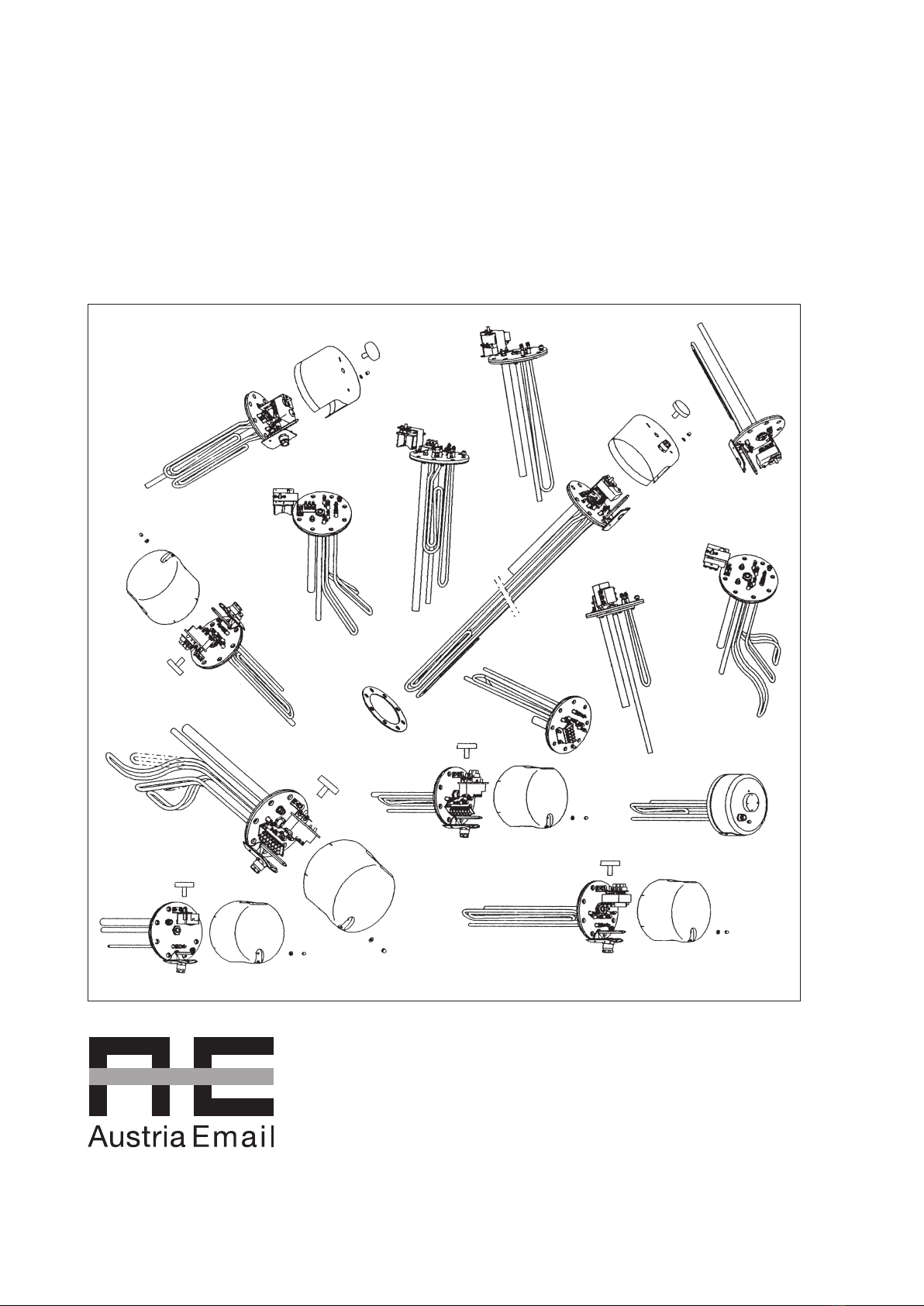
EBH-KDW
EBH-TDW
Operating and Mounting Instructions
Please pass on to the user!
Id.Nr.: 228557-10
2
Id.Nr.: 228557-10
Dear customer!
The built-in electric heaters are manufactured in accordance with the applicable regulations.
The installation and first commissioning must be performed by a licensed plumber and in accordance with these instruc-
tions only.
You will find all important information for correct assembly and operation of the built-in heater in this small brochure.
Nevertheless, let your concessionary demonstrate to you how to operate the device and explain its function after comple-
ted installation.
Of course, our customer service and sales department are readily available to support you in case you need any advice.
Enjoy the use of your built-in electric heater.
1. Function ............................................................................................................................U......E.......................3
2. Energy Saving...................................................................................................................U......E.......................3
3. Operating Requirements...........................................................................................................E.......................3
4. Information for Assembly and Installation ...............................................................................E.......................3
5. Information for Assembly and Installation ......................................................................U......E.......................4
5.1 General Information for Installation .......................................................................................E.......................4
5.2 Assembly of Built-in Heater..................................................................................................E.......................5
5.3 Information on Corrosion Protection.....................................................................................E.......................5
5.4 Water Connection of Tank....................................................................................................E.......................6
5.5 Electrical Connection ...........................................................................................................E.......................6
5.6 Circuit Diagrams ..................................................................................................................E.......................7
5.7 First Commissioning ............................................................................................................E......................11
6. Inspection, Maintenance, Service ............................................................................................E......................11
7. Malfunctions .....................................................................................................................U......E......................11
8. Warranty, Guarantee and Product Liability .....................................................................U......E......................12
TABLE OF CONTENTS .........................................................................................................Page
Information for: U=User
E=Expert

Id.Nr.: 228557-10
3
1. Function U E
The electric built-in heaters are service and maintenance-free as the main heating unit for electrically heated hot water tanks.
Only in the case of heavily calciferous water it may be necessary to free the heating units from boiler scale in certain intervals.
The desired temperature can be selected by the user on the control toggle. The heating is switched on automatically by the
temperature control, during the heating period determined by the relevant ESC, and off again when the desired tank water
temperature is reached. If the water temperature drops, e.g. by the withdrawal of water or natural cooling-off, then the de-
vice heating switches on again until the pre-selected tank water temperature is reached.
2. Energy Saving U E
Low tank water temperatures prove to be particularly economical. Therefore, the progressively adjustable temperature
should only be selected as high as necessary for the actual hot water demand. This helps to save electricity and reduces
furring in the tank.
3. Operation and Temperature Setting U E
The tank water temperature can be set progressively using the temperature selector or by the four indicated main grades
in accordance with your hot water demand. This way, an energy-conscious operation of the built-in heater is possible:
As a setting aid, the toggle of the electric heater’s temperature control has 4 indicated main stages, namely:
Position: frost protection for the tank (up to 30 °C)
Position: approx. 40°C, hand warm tank water
Position: •• approx. 65°C, moderately hot tank water
This position is recommended to rule out unintentional scalding by excessively hot water.
The device operates particularly economically in this setting.
The heat losses are minor and the formation of boiler scale is largely avoided.
Low standby energy consumption.
Position: ••• approx. 85°C, hot tank water
Caution:
Control toggle at left limit stop does not result in an off position or shutdown of the device heating.
The temperature control should not be set higher than the position •• (approx. 65°C) when operated using day current.
Due to the hysteresis of the temperature control (± 7°K) and possible radiation losses (cooling-down of the pipelines), the
temperature specifications are subject to an accuracy of ± 10°K.
4. Operating Requirements U E
The built-in heating must be used exclusively in accordance with the requirements (operating pressure, heating time, supply
voltage, etc.) specified on the rating plate. The power connection must be performed in accordance with the connec-
tion diagram affixed to the inside of the protective cap.
In addition to the legally approved national regulations (ÖVE, VDE, ÖNORM or DIN, etc.), the connecting requirements of
the local power company and waterworks as well as the Assembly and Operating Instructions must also be complied with.
In the case of heavily calciferous water, we recommend the upstream integration of a customary antiliming device.
This built-in heater is particularly suitable for installation in enamelled free-standing tanks as well as double shell units. Due
to the special design, however, these units may also be installed in foreign makes with enamelled, plastic-coated or hot-
dip galvanised boilers. A combination with CrNi (NIRO) boilers is problematic and therefore not recommended (for
necessary measures see section 5.3).
For the purpose of installation in enamelled boilers, our built-in heaters, screw-mounted heating units and built-in finned
tube heat exchangers are designed using structurally isolated heating units in conjunction with a guard circuit shunt resistor
and are therefore in compliance with the state of the art, particularly with regard to the corrosion protection of enamelled
boilers. All heating installations are suitable for pressure-proof operation and the heating up of drinking or heating water up
to a maximum operating pressure of 10 bar.
This device is not designed to be used by persons (including children) with physical, sensory or mental disabilities or lacking
experience and/or lacking knowledge, unless these are supervised by a person who is responsible for their safety or have
received instructions on how to use this device from any such person. Children should be supervised in order to ensure
that they do not play with this device.
Built-in heating systems are not suitable for use in aggressive media (alcohol, glycol, oil, etc.)!
Should a device, at the point of delivery, clearly display a malfunction, damage or other defect, this must not be fitted,
installed or used in the system. Subsequent complaints regarding devices with an obvious defect which have been con-
nected and installed are expressly excluded under the warranty and guarantee.

4
Id.Nr.: 228557-10
5. Information for Assembly and Installation E
5.1 General Information for Installation E
The heating unit and the sensor protection tube must be surrounded completely by sufficient water during operation. The
thermally-induced flow of water must not be obstructed.
The built-in heater is equipped with a safety temperature limiter, which stops any further heating of the device from a water
temperature of max. 110°C (EN 60335 -2-21; ÖVE-EW41, Part 2 (500) / 1971). Therefore, the connecting components
(connecting pipes, safety valve combinations, etc.) must be selected in such a way that they resist temperatures of 110°C
and any consequential damages are avoided in the event of any malfunction of the temperature control.
Assembly and installation must be performed exclusively by licensed craftsmen.
Fitting position:
The flange must not be longer than max. 130 mm, so that the thermometer and the heating unit still project into the hot
water tank sufficiently.
The built-in heating unit must be installed as far down as possible in the boiler, in order to heat up the entire boiler con-
tents equally. Thereby, it is not of importance whether the heating elements reach across the full fitting depth available.
Space must be kept free in front of the boiler flange (fitting length + 100 mm) for assembly, etc.
The function is impaired by the formation of boiler scale. Appropriate measures must be taken in the case of heavily calci-
ferous water: e.g. lowering of temperature, installation of a softening system, removal of the boiler scale.
Flange frame too long and
welded-in too high.
Temperature control below
heating unit.
CORRECT WRONG
Heating unit
Heating unit
COLD ZONE COLD ZONE
Temperature
control

Id.Nr.: 228557-10
5
5.2 Assembly of Built-in Heater E
In addition to the legally approved regulations, the connecting requirements of the local power company and waterworks
must be complied with.
1. Remove cover on tank.
2. Install heating flange “item 2” in boiler using sealing ring “item 3”.
The sensor protection tube of the temperature control must be located above the tubular heating unit(s)
when installed (see information for installation).
3. Attach the heating flange “item 2” using flange screws M12 (max. turning moment 22 Nm).
Tighten the flange screws crosswise.
The screwed connection of the heating unit must be checked and retightened using a turning moment of
2-3 Nm, if necessary.
4. Produce power connection according to the circuit diagram (see section 5.5).
Important – do not forget: connect protective conductor!
5. Mount covering cap “item 1” on tank. Put on enclosed control toggle “item 4”, set desired service water
temperature.
6. Do not put into operation until the tank is filled with water.
The assembly of the heating installation and the initial start-up must be performed exclusively by an expert, who thereby
accepts responsibility for proper implementation and equipping.
5.3 Information on Corrosion Protection U E
The built-in heater is designed for installation in enamelled tanks. If the heater is installed in foreign makes, then the sup-
plier of the boiler must ensure sufficient corrosion protection. First control of the anode is after approx. 2 years operating
time. The protective anodes should be replaced if more than 3/4 of the material have degraded.
The following measure is required in the event of a combination with CrNi (NIRO) tanks or CrNi heat exchangers and
installations in plastic-coated tanks:
a) Disconnect the guard circuit shunt resistor to ensure insulated installation of the heating unit.
6
Id.Nr.: 228557-10
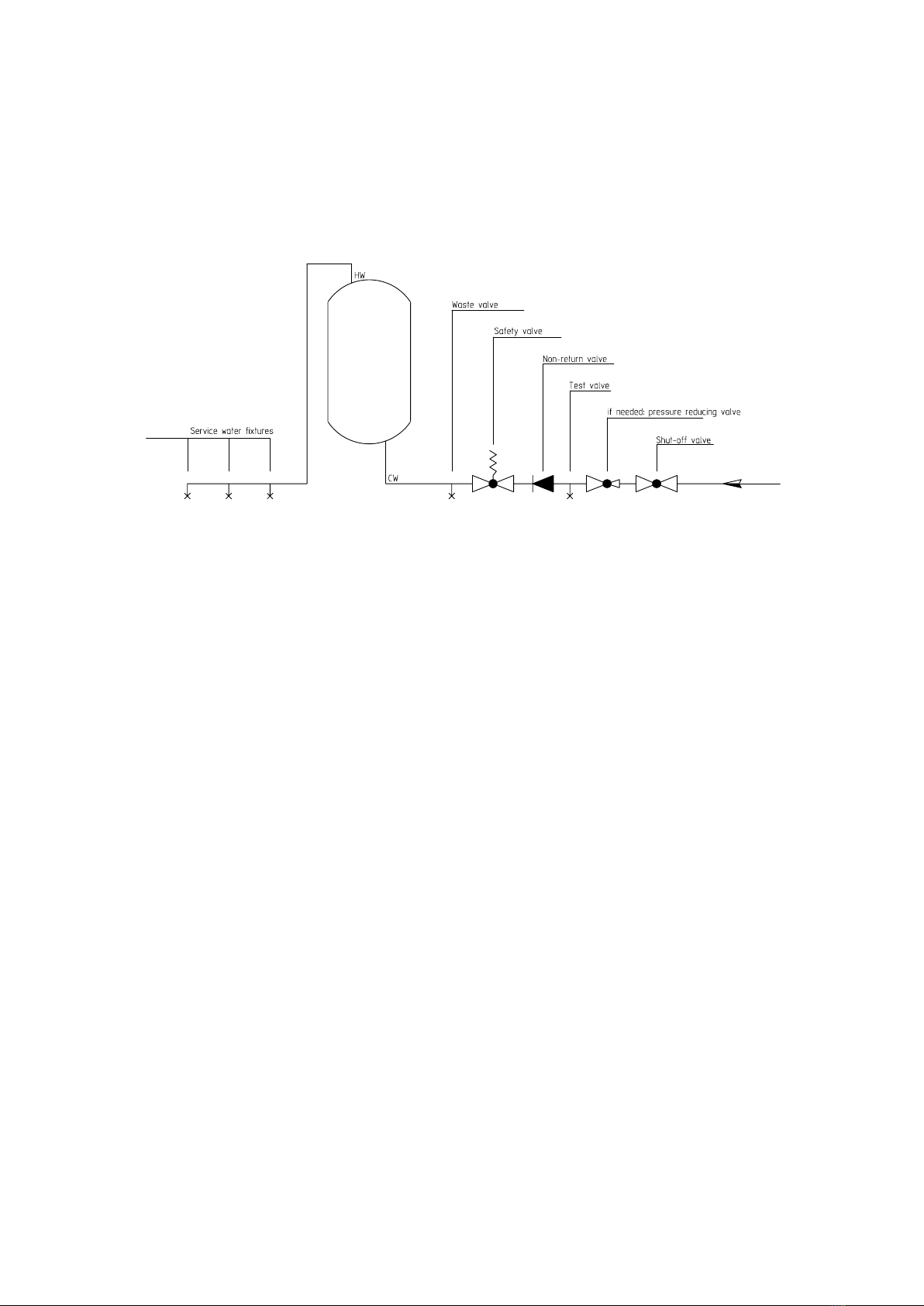
5.4 Water Connection of Tank E
It is imperative that the mounting, connecting and operating instructions of the hot water tank (boiler) are complied with.
Pressure-proof connection:
Any warranty shall be rejected in the case that unsuitable or inoperative tank connector fittings are used as well as in the
event of any exceedance of the specified operating pressure.
The plumbing must be performed exclusively using a design certified diaphragm safety valve or a combined diaphragm
safety valve connector fitting for pressure-proof storage tanks!
A safety valve combination (see “Tank connection pursuant to DIN 1988”) is installed in the cold water supply line (blue) of
the tank in the order as drawn.
5.5 Electrical Connection E
The connection with the power grid must be implemented in conformity with the applicable national regulations and stan-
dards, the relevant connecting requirements of the local power company and waterworks, as well as the standards of the
Mounting and Operating Instructions, and must be performed exclusively by a licensed electrician. The stipulated protec-
tive measures must be executed carefully, so that no other power-supplied devices are affected thereby in the event of a
malfunction or failure of the hot water tank’s power supply (e.g. freezer, rooms used for medical purposes, units for inten-
sive care, etc.).
In rooms with bathtubs or showers, the device must be installed in accordance with the national laws and regulations (e.g.
of ÖVE-SEV, VDE or DIN VDE 0100-701).
The technical connecting requirements (TAB) of the relevant energy supply company must absolutely be observed.
A residual current circuit breaker with a tripping current I∆N≤30mA must be connected in series before the electric circuit.
The device must only be connected with permanently laid lines.
These types of water heaters are to be supplied exclusively via a hard-wired connection cable and are therefore not sui-
table for connection via a shock-proof plug (SKI). Accidental activation of the upstream RCD is to be avoided in this way.
An all-pole disconnecting unit with at least 3mm contact clearance must be connected in series before the device. This
requirement is fulfilled e.g. by an automatic cutout.
It is imperative that the hot water tank is filled with water prior to electrical start-up.
In accordance with the safety regulations, the hot water tank must be switched powerless, secured against being swit-
ched on again and checked for powerlessness prior to any intervention. Interventions to the electrics of the device must
only be performed by a licensed electrician.
As a rule, the electrical connection must be performed in accordance with the circuit diagram affixed inside the connec-
ting area of the tank!
Id.Nr.: 228557-10
7
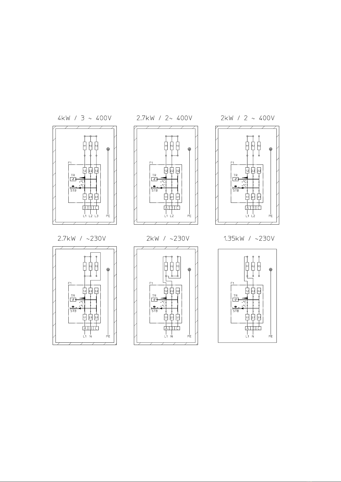
5.6 Circuit Diagrams E
EBH-KDW1 4,0kW
EBH-TDW1 4,0 kW
Heating elements
3 x 1,35 kW / 230 V
3 x 40 Ohm
Circuit in factory conguration
4,0 kW / 3~400V
200 litres
4 hrs. / 4,0 kW
6 hrs. / 2,7 kW
8 hrs. / 2,0 kW

8
Id.Nr.: 228557-10
EBH-KDW1 6,0kW
EBH-TDW1 6,0 kW
Heating elements
3 x 2,0 kW / 400 V
3 x 80 Ohm
Circuit in factory conguration
6,0 kW / 3~400V
300 litres
4 hrs. / 6,0 kW
6 hrs. / 4,0 kW
8 hrs. / 3,0 kW

Id.Nr.: 228557-10
9
EBH-KDW1 8,0kW
EBH-TDW1 8,0 kW
Heating elements
3 x 2,7 kW / 400 V
3 x 60 Ohm
Circuit in factory conguration
8,0 kW / 3~400V
400 litres
4 hrs. / 8,0 kW
6 hrs. / 5,0 kW
8 hrs. / 4,0 kW

10
Id.Nr.: 228557-10
EBH-KDW1 10,0kW
EBH-TDW1 10,0 kW
Heating elements
3 x 3,3 kW / 400 V
3 x 48 Ohm
Circuit in factory conguration
10,0 kW / 3~400V
500 litres
4 hrs. / 10,0 kW
6 hrs. / 6,5 kW
8 hrs. / 5,0 kW

Id.Nr.: 228557-10
11
5.7 First Commissioning U E
The tank must be filled with water before switching on the electricity.
The expansion water created in the internal boiler during the heating process must drip from the safety valve in the case of a
pressure-proof connection, and from the overflow mixing tap in the case of an unpressurised connection.
Caution: the hot water drain pipe as well as parts of the safety fitting may become hot.
The preset temperature, the actual temperature of the water withdrawn and the hot water quantity display should correspond
approximately after completion of the heating process.
6. Inspection, Maintenance, Service U E
The boiler scale as well as the furring that forms in the internal boiler of the storage tank in the case of heavily calciferous
water must be removed by an expert after one to two years of operation. The cleaning is performed through the flange
opening – de-install the built-in heater, clean the storage tank, use a new seal when mounting the heating flange.
The internal tank of the water heater with special enamelling must not get in contact with boiler scale solvents – do not
use an antiliming pump.
Finally, the device must be rinsed thoroughly and the heating process be observed in the same way as during the first
commissioning.
In order to be entitled to any claims for warranty, as provided on the part of AE AG, the installed reactive anode requires
documented inspection by an expert in intervals of maximum 2 years of operation. Practically, the external current anode
has an unlimited service life. Its function must be monitored regularly by means of the control lamp. This indicates two
operating conditions:
Green: system ok
Red, flashing: malfunction - call customer service!
Pre-requisite for flawless functioning is that the tank is filled with water. For proper functioning of the external current anode,
a conductivity of the medium of >150 µs/cm is required.
The guard circuit shunt resistor must not be damaged or removed during maintenance works.
Do not use any abrasive cleaning agents and paint thinners (such as nitro, trichlor etc.) to clean the device.
The best cleaning method is to use a damp cloth added with a few drops of a liquid household cleaner.
During servicing works, it is advisable to open the cleaning and servicing flange in order to inspect the tank for any foreign
objects that may have been washed in as well as any contamination, and to remove any such, if applicable.
7. Malfunctions U E
If the tank water is not heated, please check whether the line circuit breaker (automatic safety cutout) or the safety fuse in
the distribution box have reacted, and check the setting of the temperature control.
In all other cases, do not attempt to rectify the fault yourself. Please contact either a licensed plumber or our customer ser-
vice. In many cases, experts only need to do a few little jobs and the storage tank works again. During notication, please
quote your model designation and manufacturing number, which you can nd on the rating plate of your built-in heater.

Warranty, Guarantee and Product Liability
The warranty is granted in accordance with the statutory provisions of the Republic of Austria, as well as of the EU.
1. Prerequisite for the provision of warranty services by Austria Email AG (hereinafter referred to as AE AG) shall be the presentation of the paid invoice for the
purchase of the device for which the warranty service is claimed, whereby the identity of the device with regard to the model and the manufacturing number must
be evident from the invoice and must be documented by the claimant. The General Terms and Conditions, Terms and Conditions of Sale and Delivery of AE AG
shall apply exclusively.
2. To the extent required by the law, respectively in the Operator’s Manual and Installation Instructions, the assembly, erection, connection and commissioning of the
unit for which the claim is presented must have been carried out by a licensed electrician or installation rm, duly observing all applicable rules. The tank (without
outer shell and plastic outer shell) must be protected from sunshine to avoid discolouring of the PU foam and potential warping of plastic components.
3. The room in which the device is operated must be free of frost. The unit must be mounted in a location that may reasonably be expected, i.e. it must be possible to
access and replace the unit without difculty for the purpose of necessary maintenance, repairs and possible replacement. The costs for any necessary changes
to the structural conditions (e.g. doors and passages too narrow) are not governed by the guarantee and warranty declaration and therefore shall be rejected on
the part of AE AG. If the water boiler is set up and operated in uncommon locations (e.g. attics, living rooms with water-sensitive oors, store rooms, etc.), the pos-
sibility of water leakage must be taken into account and provisions made for collecting and discharging the water leakage in order to prevent secondary damage
within the meaning of product liability.
4. The following is not covered by the warranty and guarantee:
inappropriate transport, normal wear and tear, intentional or negligent damage, use of force of any kind or description, mechanical damage or damage caused by
frost or also by exceeding the operating pressure stated on the rating plate, even if only once, use of connection ttings that do not comply with the standard, use
of defective tank connection ttings and unsuitable and defective service ttings. Breaking of glass and plastic components, possible colour differences, damage
due to improper use, in particular non-observance of the mounting and operating instructions (Operating and Mounting Instructions), damage by external inuence,
connecting to incorrect voltage, corrosion damage as a consequence of aggressive waters (water not suitable for drinking) in accordance with the national regula-
tions (e.g. Austrian ordinance on drinking water, TWV – Fed. Law Gazette II No. 304/2001), deviations between the actual drinking water temperature at the tank
tting and the specied hot water temperature of up to 10°K (hysteresis of the controller and possible cooling due to pipelines), Insufcient water conductivity (min.
150 µs/cm) operational wear of the magnesium anode (wearing part), natural formation of boiler scale, lack of water, re, ood, lightning, overvoltage, power failure
or other types of force majeure. Use of non-original and company-external components such as e.g. heating elements, reactive anode, thermostat, thermometer,
ribbed tube heat exchanger, etc., Parts installed in an uninsulated condition with respect to the storage tank, ingress of foreign particles or electrochemical inu-
ences (e.g. mixed installations), failure to observe the design documents, unpunctual and undocumented renewal of the installed protective anode, no or improper
cleaning and operation, as well as any deviations from the standard that reduce the value or functionality of the device only slightly. Fundamental compliance with
all regulations in ÖNORM B 2531, DIN 1988 (EN 806), DIN 1717, VDI 2035 or the corresponding national regulations and laws must be ensured.
5. In the case of an authorised complaint, this must be reported to the next available customer service location of AE AG. The same reserves the right to decide
whether a defect component shall be replaced or repaired or whether a defect device shall be replaced by an equivalent fault-free device. Furthermore, AE AG
explicitly reserves the right to request that the rejected device be returned by the buyer.
6. Repairs under warranty must be performed exclusively by persons authorised to do so by AE AG. Replaced parts shall remain the property of AE AG. If a repair of
the hot water heater should be required in connection with necessary service work, the Manufacturer shall invoice these as repair and prorated material costs.
7. Any intervention by third parties without our express instruction, even if performed by a licensed electrician, shall have the effect of voiding the warranty. Costs for
repairs carried out by third parties shall be replaced only if AE AG has previously been requested to remove the defect and if AE AG shall have failed to satisfy its
obligation to replace the defective item or repair the defect or if it shall have failed to do so within a reasonable period of time.
8. Neither the performance of works under warranty or guarantee, nor the performance of service and maintenance works shall renew or extend the term of warranty.
9. Transport damage shall be investigated and possibly accepted only if it is reported to AE AG in writing on the next following workday after delivery at the latest.
10. Claims over and above the warranty, if legally permissible, in particular claims with respect to compensation of damages and consequential damages, shall be
excluded. Prorated labour time for repairs as well as the costs of restoring the original condition of the unit must be paid in full by the buyer. In accordance with
this warranty declaration, the warranty shall apply only to repair or replacement of the unit. The provisions of the Terms and Conditions of Sale and Delivery of AE
AG shall, unless amended by these Terms and Conditions of Warranty, remain fully in place.
11. Services that are not performed within the scope of these Terms and Conditions of Warranty shall be charged.
12. No claims under warranty shall be considered by AE AG unless full payment for the device has been made to AE AG and unless the claimant has fully satised
all obligations arising to him vis-à-vis the seller.
13. The enamelled internal boiler for water heaters is warranted for the specied period from the delivery date provided all warranty terms described under Points 1
to 12 are observed with in full. If the warranty terms have not been met, the legal warranty requirements of the respective country from which the appliance was
shipped shall prevail.
14. With regard to the assertion of claims pursuant to the Austrian Product Liability Act it must be noted:
Potential claims under the title of product liability relating to the regulation of damages due to a defective product (e.g. a human’s body is injured, his health is
damaged or any corporeal property differing from the product is damaged) shall only be justied if all the prescribed measures and requirements for awless and
normal operation of the unit have been fullled.
These include e.g. the mandatory and documented anode replacement, the connection to the correct operating voltage, any damage due to improper use must be
avoided, etc. These standards are based on the assumption that if all the regulations (standards, assembly and operating instructions, general guidelines, etc.) are
observed, the defect in the unit or product causal for occurrence of the secondary damage would not have occurred. It is further imperative that all the documen-
tation necessary for handling of a claim, such as e.g. the type and fabrication number of the unit, the vendor’s invoice and the invoice of the licensed electrician or
installation rm, as well as a description of the malfunction be provided, as well as the defective unit itself for examination in the lab (absolutely necessary, as the
unit will be investigated by an expert and the cause of the defect analysed). In order to exclude any possibility of mistaken identity of the unit during transportation,
the unit must be labelled with a clearly legible label (ideally with the end customer’s address and signature). Appropriate photographic documentation of the extent
of damage, the installation (cold water inow, hot water outow, heating inow and outow, safety ttings, expansion vessel if applicable), as well as the defective
part of the tank is required. AE AG further expressly reserves the right to demand the submission of documentation and units or unit components by the buyer for
the purpose of clarication.
The damaged party’s full burden of proof that the damage was caused by the product of AE AG is prerequisite for the payment of any benets under the title of
product liability. Claims for damages pursuant to the Austrian Product Liability Act are moreover justied only for any amount exceeding the amount of 500 euros
(deductible amount). Until all the facts and circumstances as well as the problem causally underlying the defect have been ascertained, any possible fault on the
part of AE AG shall be ruled out explicitly. Any non-observance of the operating and assembly instructions as well as the relevant standards shall be deemed
negligence and shall result in an exclusion of any liability for damages.
The gures and data are not binding and may be amended without notice in the interest of technical improvement.
Misprints and technical changes reserved.


Id.Nr.: 228557-10
Austria Email AG
Austriastraße 6
A-8720 Knittelfeld
Telefon: (03512) 700-0
Fax: (03512) 700-239
Internet: www.austria-email.at
E-Mail: of[email protected]
Austria Email in your area?
For addresses and telephone numbers of our subsidiaries,
visit our homepage at www.austria-email.at
Print errors and changes of all kinds are reserved.
Reproduction prohibited.
Other manuals for EBH-KDW
1
This manual suits for next models
1
Table of contents


