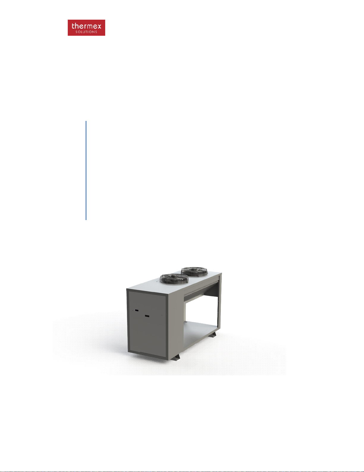
THERMEx THW20 User manual

Heat Pump Manual
Thermex Solutions
PRODUCT MANUAL
HEAT PUMPS
Document 001-D135
11 May 2015
Models
THW20 THW40 THW60 THW80 THW100 THW150
THWW20 THWW40 THWW50 THWW60 THWW80 THWW100
THWP20 THWP40 THWP60

Heat Pump Manual
2
Terms and Conditions
Listed below are some basic operational and installation conditions that must be adhered to for
Thermex Solutions warranty to remain valid and more importantly for trouble free heat pump
operation
·If the heat pump is supplied without a pump then the minimum flow rate specified in the manual
must be maintained through the units at all times.
·The heat pump must be commissioned in accordance with the instruction in the manual and
the heat pump must be commissioned under normal operating conditions
·The operational settings on the controller must not be altered without first consulting Thermex
·The temperature cut out set point must never be set above 61°C without first consulting
Thermex Solutions
·The heat pump must be installed on level surface
·The heat pump must be powered up for at least 4 hours before starting the heat pump to allow
for the sump heater to warm the compressor oil.
·The pressure in the sealed refrigeration system must be checked by a refrigeration mechanic
before starting the heat pump to ensure that the pressure on the suction side is at least 200
kPa
·For any service work not carried out by Thermex Solutions, Thermex Solutions will only cover
costs of refrigerant to the value of the specified charge in the units.
·It is not Thermex Solutions’s responsibility to connect the heat pump to the BMS unless agreed
to before delivery of the heat pump
·The heat pump must not be installed too close to walls and other heat pumps with clearances
to be at least what is specified in the manual
·The heat pump must be installed with proper, neat access to facilitate servicing in a manner
that is compliant with safe work practices. Additional charges may apply for site where access
to the heat pump is unsafe or restricted
·Thermex Solutions will manufacture the heat pump to the specification provided to the sales
department. If the information supplied is incorrect Thermex Solutions takes no responsibility
for wear on the heat pump for short cycling in the case where the heat pump is over sized for
the heat load or the heat pump unable to maintain temperature when the heat pump is too
small for the heat load
·Thermex Solutions takes no responsibility for repairs carried out on the heat pump by un-
authorised service agents or if parts are installed that are not from Thermex Solutions’s
approved supplier list
·Costs for installations where a crane lift is required to undertake major repairs will not be
covered by Thermex Solutions
·All dimensions, technical specifications and software operation are correct at the time of
writing. However with constant development some of these specifications may change without
written notice

Heat Pump Manual
3
FOREWARD
This manual is designed to explain the installation, operation and the basic maintenance of
the product. It is recommended that for service issues Thermex Pty Ltd be contacted before
and work commences. A comprehensive service manual is available to be down loaded from
the website.
CONTACT DETAILS
Thermex Solutions Pty Ltd
161 Orchard Road
Chester Hill NSW 2162
Australia
Toll Free 1800649233 or +612 9721 9300
Fax + 612 9721 9344
www.thermex.com.au
CONTENTS
Safety 4
Marking 6
Certification 6
Warranty 7
General Information 7
Intended Use 7
Water Circuit 7
Technical Data 8
Heating System Schematic 16
Dimensions 17
Transport and Storage 19
Installation –electrical, water connection, water treatment, control circuit and final
checks 19
Operation 27
Control 29
Service and Maintenance 31
Wiring 37
Pump Curves N/A
Critical Spares 38
Trouble Shooting 39
Release Notes 40
Commissioning 41
Site Inspection 44

Heat Pump Manual
SAFETY
THE UNITIS DESIGNED FOR OUTDOOR USE.
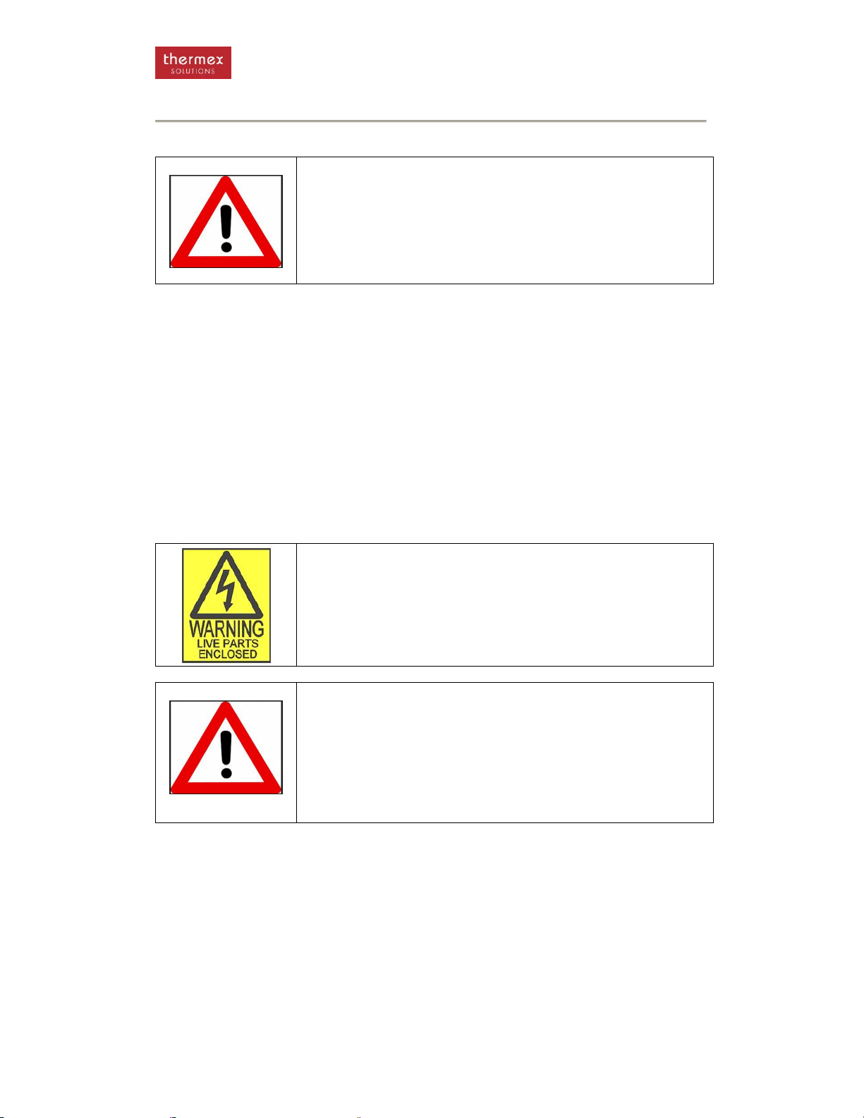
WARNING
The unit is only to be installed, operated, maintained and serviced by
qualified persons only. Operation of units such as these can be hazardous
and should be serviced by persons with the proper training and
qualifications.
The unit and the Product Manual have markings, warning and instructions
on the safe operation of the unit and they must be adhered to.
- This unit is designed to be safe in the use for which it was planned provided that it is
installed, started up and maintained in accordance with the instructions contained in
this manual.
- The unit contains electrical components that operate at line voltage and contains
moving parts. It therefore must be isolated from the electrical supply before being
worked on. All maintenance operations that require access to the unit must be carried
out by suitably qualified technicians who have a thorough understanding of all
necessary precautions associated with refrigeration and electrical machinery.
- The liquids to be heated must be compatible with the materials used in the
constructions of this unit. These liquids can be water or mixtures of glycol and water
for example. The liquids to be heated must not be flammable.
- All panels must be re-installed after carrying out any maintenance work.
- The unit is not to be used by the infirmed or children unless they are supervised by
responsible persons qualified to carry out the supervision.
- The unit should be secured to prevent it from toppling over.
WARNING
All wiring must be performed by qualified electricians. Improperly installed
wiring and grounding may result in electrocution and fire hazards
To avoid these hazards all wiring must be installed in accordance with all
the local relevant safety standards for wiring
WARNING
The heat pump contains refrigerants under high pressure. The system also
contains oils under high pressure. Before the refrigeration circuit can be
opened, the refrigerant should be reclaimed to reduce pressure in the
system.
Failure to recover the refrigerant to relieve pressure or the use of
refrigerants or refrigerant substitutes that are not specified for the unit may
result in system rupture and explosion.
- Where the above symbol is shown there are live electrical parts and the utmost care
should be taken. .
- Always isolate power from the unit when working on it.
- Maximum temperature setting is 60 degrees on the unit. Any higher than this may
cause problems with the condenser and/ or the water system over heating which may
become dangerous
Refrigerants have a narcotic effect when inhaled in high quantities. Should a leak occur of the
refrigerants then the room should be vacated and should only be re-entered after suitable
ventilation.

Heat Pump Manual
5
SAFETY
First Aid
- Eye Contact. Immediately flush with tepid water or sterile saline solution. Hold eyelids
apart for 15 minutes while irrigating. Seek medical attention.
- Inhalation. Remove from area of exposure immediately and if you are assisting a
victim avoid being exposed. Breathing apparatus must be worn in the presence of
high concentration of refrigerants. If victim is not breathing then apply artificial
respiration and seek urgent medical help. Give oxygen is available.
- Skin Contact. Cold Burns. Remove contaminated clothing and gently flush affected
area with warm water (30C) for 15 minutes. Apply sterile dressing and treat as for a
thermal burn. For large burns immerse in water for 15 minutes. DO NOT apply any
form if direct heat. Seek medical attention.
- Ingestion. For advice contact the poisons centre on 131126 in Australia. If swallowed
do not induce vomiting. Ingestion is considered unlikely due to product form.
- Advice to Doctor. Use of adrenaline and other catacholamines may be contraindicted
due to possible cardiac sensation. Treatment for asphyxia.
R134a HazChem code 2RE
R134a is non –flammable.
Disposal
The unit must be disposed of in a proper fashion. The refrigerants in the system must be
reclaimed by a qualified refrigeration mechanic and disposed of in accordance with the
statutory requirements. The compressor contains oil that must not be dumped.
Manual Handling
The unit weights approximately 650 kg. Do not try to move the unit manually. The unit can be
lifted with a crane (the centre of gravity is towards the front of the unit), a forklift or a pallet
jack.

Heat Pump Manual
6
MARKING
The units have various markings on them. There is a marking plate on the unit, an example is
shown below giving regulatory requirements. There will be a wiring diagram as shown in the
wiring diagram section of this document provided in a larger scale for ease of maintenance.
A four digit serial number sticker will also be placed under the marking plate. With this number
Thermex can trace the date of manufacture of the product and details on the unit.
The wiring diagram will show the model of the unit and the options installed.
CERTIFICATION
All the electrical components in the heat pump have certification for electrical safety. All the
exposed components are rated to IP66 against weather ingress.
All Thermex products are manufactured by Aqua Cooler in
Australia. Aqua Cooler is an accredited participant in the
WaterMark QA scheme and is audited annually by SAI Global
The Watermark scheme cover all products that are connected
to the town water supply.

Heat Pump Manual
7
WARRANTY
Thermex offers a full comprehensive 12 month parts warranty, 5 years on the compressor
and the condenser.
Any claim under this warranty must be made within 12 months of the date of purchase of the
product. To make a claim under the warranty, return the product (with proof of purchase) to
the supplier where you purchased the product or contact Thermex regarding warranty
conditions.
Thermex will pay your reasonable, direct expenses of claiming under this warranty. You may
submit details and proof of your expense claim to Thermex Pty Ltd for consideration.
This warranty is given by Thermex Pty Ltd, ABN 13 245 994 351, of 161 Orchard Rd, Chester
Hill, NSW 2162 –Ph 02 9721 9310.
This warranty is provided in addition to other rights and remedies you have under law: Our
goods come with guarantees which cannot be excluded under the Australian Consumer Law.
You are entitled to replacement or refund for a major failure and to compensation for other
reasonably foreseeable loss or damage. You are also entitled to have the goods repaired or
replaced if the goods fail to be of acceptable quality and the failure does not amount to a
major failure.
Attached to this document is a comprehensive commissioning procedure. This must be
carried out in accordance with the procedure and returned to Thermex or Thermex can do the
commissioning, otherwise the warranty will be voided.
GENERAL INFORMATION
The heat pump is designed to heat water to feed a central storage system. It has either an air
cooled copper and aluminium fin or a coaxial copper water sourced evaporator, a plate heat
condenser and a scroll compressor to circulate the refrigerant gas. Water is circulated out of
the unit via a pump which is not supplied with the unit. The unit has a microprocessor
controller to maintain temperature, control additional heat pumps and monitor flow through the
unit for safety reasons.
INTENDED USE
The heat pump is design to be installed outdoors and heat water to be storage in a remote
central storage location. The wetted parts in the heat pump are food grade however Thermex
takes no responsibility for the quality of the water being heated. Any other use of this water
heat pump is a not as it is intended.

Heat Pump Manual
8
HOT WATER CIRCUIT
The hot water circuit consists of
1. Condenser heat exchanger –this may be a plate heat exchanger, a coaxial heat
exchanger or shell and tube
2. Flow switch or flow meter
3. Copper pipe work
The heat pump will run whenever called unless the controller detects a drop in flow.
It is important to ensure that any water treatment is passive to the wetted parts of the system
which include
·Stainless Steel
·Copper
·High Density Polyethylene
·Brass
·ABS Plastic
·Nitrile Rubber
The water to water models have a water sourced evaporator that is connected to –typically –
the return condenser water from the installed chillers. This evaporator can have either a plate
heat exchanger or a coaxial heat exchanger. These heat exchangers have water flowing
through them that must be passive to the materials used. These include
·Stainless steel –316
·Copper
·Brass

Heat Pump Manual
9
TECHNICAL DATA
AIR TO WATER HEAT PUMPS
All units have a details data sheet available –the information supplied below is
intended as a guide only –please contact Thermex for a copy of the individual model
data sheets
Model
THW07
Nomina
l heating capacity
–
kW
7
Rated duty point
–
in red
20°C Ambient conditions 45°C Water supply 60% RH
Water Supply Temperature
45°C
50°C
55°C
60°C
65°C
70°C
Heating Capacity –kW 10°C Ambient
5.48
5.37
5.27
5.19
5.16
5.13
Power Input –kW
1.51
1.6
7
1.85
2.05
2.13
2.19
COP
3.63
3.22
2.85
2.53
2.42
2.34
Heating capacity –kW 20°C Ambient
6.43
6.27
6.10
5.99
5.95
5.91
Power Input –kW
1.53
1.69
1.88
2.08
2.16
2.22
COP
4.20
3.71
3.24
2.88
2.75
2.66
Heating Capacity –kW 30°C Ambient
7.52
7.
31
7.12
6.92
6.84
6.78
Power Input –kW
1.54
1.71
1.90
2.10
2.18
2.24
COP
4.88
4.27
3.75
3.30
3.14
3.02
Model
THW10 and THWDW10
Nominal heating capacity
–
kW
10
Rated duty point
–
in red
20°C Ambient conditions 45°C Water supply 60% RH
Water Supply Temperature
45°C
50°C
55°C
60°C
65°C
70°C
Heating Capacity –kW 10°C Ambient
8.11
7.94
7.79
7.65
7.59
7.55
Power Input –kW
2.19
2.43
2.69
2.97
3.08
3.17
COP
3.70
3.27
2.90
2.58
2.46
2.38
Heating capacity –kW 20°C Ambient
9.51
9.27
9.05
8.83
8.74
8.67
Power Input –kW
2.21
2.45
2.72
3.01
3.13
3.22
COP
4.30
3.78
3.33
2.93
2.80
2.69
Heating Capacity –kW 30°C Ambient
11.15
10.84
10.51
10.22
10.10
10.01
Power Input –kW
2.23
2.48
2.74
3.04
3.16
3.26
COP
5.00
4.37
3.84
3.36
3.20
3.07
Mo
del
THW12 and THWDW12
Nominal heating capacity
–
kW
12
Rated duty point
–
in red
20°C Ambient conditions 45°C Water supply 60% RH
Water Supply Temperature
45°C
50°C
55°C
60°C
65°C
70°C
Heating Capacity –kW 10°C Ambient
10.59
10.39
10.29
9.86
9.6
9
9.55
Power Input –kW
2.69
2.99
3.34
3.71
3.86
3.98
COP
3.94
3.47
3.08
2.66
2.51
2.40
Heating capacity –kW 20°C Ambient
12.41
12.16
11.91
11.69
11.60
11.53
Power Input –kW
2.71
3.01
3.35
3.74
3.90
4.02
COP
4.58
4.04
3.56
3.13
2.98
2.87
Heating Capacity –kW 30°C Ambient
14.55
14.20
13.83
13.51
13.38
13.28
Power Input –kW
2.75
3.05
3.38
3.76
3.91
4.03
COP
5.29
4.66
4.09
3.59
3.42
3.29

Heat Pump Manual
10
TECHNICAL DATA
AIR TO WATER HEAT PUMPS
Model
THW20 and THWDW20
Nominal heating capacity
–
kW 20
Rated duty point
–
in red
20°C Ambient conditions 45°C Water supply 60% RH
Water Supply Temperature
45°C
50°C
55°C
60°C
65°C
70°C
Heating Capacity –kW 10°C Ambient
18.62
18.18
17.78
17.40
17.25
17.13
Power Input
4.77
5.28
5.83
6.40
6.63
6
.81
COP
3.90
3.44
3.05
2.72
2.60
2.51
Heating capacity –kW 20°C Ambient
21.86
21.27
20.67
20.07
19.83
19.64
Power Input
4.81
5.32
5.87
6.47
6.71
6.90
COP
4.54
4.00
3.52
3.10
2.96
2.85
Heating Capacity –kW 30°C Ambient
25.50
24.71
23.92
23.17
22.87
22.63
Power Input
4.80
5.31
5.87
6.47
6.71
6.90
COP
5.31
4.65
4.07
3.58
3.41
3.28
Model
THW30 and THWDW30
THW30H and THWDW30
Nominal heating capacity
–
kW 30
Rated duty point
–
in red
20°C Ambient conditions 45°C Water supply 60% RH
Water Supply Temperature
45°C
50°C
55°C
60°C
65°C
70°C
Heating Capacity –kW 10°C
Ambient 25.50 24.85 24.10 23.45 23.19 22.98
Power Input
6.30
7.05
7.80
8.55
8.85
9.09
COP
4.05
3.52
3.09
2.74
2.62
2.53
Heating capacity –kW 20°C Ambient
29.30
28.45
27
.50
26.45
26.03
25.69
Power Input
6.30
7.05
7.80
8.55
8.85
9.09
COP
4.65
4.04
3.53
3.09
2.94
2.83
Heating Capacity –kW 30°C
Ambient
33.40 32.30 31.15 29.80 29.26 28.83
Power Input
6.30
7.00
7.75
8.50
8.80
9.04
COP
5.30
4.61
4.02
3.51
3.33
3.19
Model
THW40 and THWDW40
THW40H and THWDW40H
Nominal heating capacity
–
kW 40
Rated duty point
–
in red
20°C Ambient conditions 45°C Water supply 60% RH
Water Supply Temperature
45°C
50°C
55°C
60°C
65°C
70°C
Heating Capacity –kW 10°C Ambient
32
.70
31.95
30.90
29.95
29.57
29.27
Power Input 8.20 9.25 10.30 11.25 11.63 11.93
COP
3.99
3.45
3.00
2.66
2.54
2.45
Heating capacity –kW 20°C Ambient
39.05
37.10
36.00
34.70
34.18
33.76
Power Input
7.55
9.30
10.30
11.50
11.98
12.36
COP
5.17
3.99
3.
50
3.02
2.85
2.73
Heating Capacity –kW 30°C Ambient
43.90
42.85
41.30
40.20
39.76
39.41
Power Input
8.40
9.35
10.30
11.50
11.98
12.36
COP
5.23
4.58
4.01
3.50
3.32
3.19

Heat Pump Manual
11
TECHNICAL DATA
AIR TO WATER HEAT PUMPS
Model
THW50 and THWDW50
THW50H* and THWDW50H
Nominal heating capacity
–
kW
50
Rated duty point
–
in red
20°C Ambient conditions 45°C Water supply 60% RH
Water Supply Temperature
45°C
50°C
55°C
60°C
65°C
70°C
Heating Capacity –kW 10°C Ambient
42.50
41.90
41.40
41.00
40.
84
40.71
Power Input
11.00
12.20
13.60
15.10
15.70
16.18
COP
3.86
3.43
3.04
2.72
2.60
2.52
Heating capacity –kW 20°C Ambient
49.60
48.80
48.20
47.30
46.94
46.65
Power Input
11.10
12.30
13.70
15.30
15.94
16.45
COP
4.47
3.97
3.52
3.09
2.94
2.84
Heating Capacity –kW 30°C Ambient
58.20
57.00
55.80
54.90
54.54
54.25
Power Input
11.20
12.50
13.80
15.40
16.04
16.55
COP
5.20
4.56
4.04
3.56
3.40
3.28
Model
THW60 and THWDW60
THW60H and THWDW60H*
Nominal heating capacity
–
kW
60
Rated duty point
–
in red
20°C Ambient conditions 45°C Water supply 60% RH
Water Supply Temperature
45°C
50°C
55°C
60°C
65°C
70°C
Heating Capacity –kW 10°C Ambient
52.65
52.05
51.40
50.70
50.42
50.20
Power Input
13.75
15.35
17.10
19.00
19.76
20.37
COP
3.83
3.39
3.01
2.67
2.55
2.46
Heating capacity –kW 20°C Ambient
61.90
60.80
59.85
59.10
58.80
58.56
Power Input
13.90
15.45
17.20
19.15
19.93
20.55
COP
4.45
3.94
3.48
3.09
2.95
2.85
Heating Capacity –kW 30°C Ambient
72.35
70.80
69.45
68.20
67.70
67.30
Power Input
14.05
15.60
17.35
19.30
20.08
20.70
COP
5.15
4.54
4.00
3.53
3.37
3.25
Model
THW80 and THWDW80
THW80H and THWDW80H
Nominal heating capacity
–
kW
80
Rated duty point
–
in red
20°C Ambient conditions 45°C Water supply 60% RH
Water Supply Temperature
45°C
50°C
55°C
60°C
65°C
70°C
Heating Capacity –kW 10°C Ambient
65.6
63.9
61.8
59.6
56.54
52.6
Power Input
16.6
18.5
20.6
22.8
24.0
23.7
COP
3.95
3.45
3.0
2.61
2.36
2.22
Heating capacity –kW 20°C Ambient
76.1
74.2
72.0
69.4
66.5
65.2
Power Input
16.7
18.6
20.6
22.1
22.8
22.9
COP
4.56
3.99
3.50
3.02
2.92
2.85
Heating Capacity –kW 30°C Ambient
87.8
85.7
82.6
80.4
77.5
76.1
Power Input
16.8
18.7
20.6
23.0
25.1
25.7
COP
5.23
4.58
4.01
3.50
3.09
2.96

Heat Pump Manual
12
TECHNICAL DATA
AIR TO WATER HEAT PUMPS
Model
THW100 and THWDW100
THW100H and
THWDW100H
Nominal heating capacity
–
kW
100
Duty point in red
20°C Ambient conditions 45°C Water supply 60% RH
Water Supply Temperature
45°C
50°C
55°C
60°C
65°C
70°C
Heating Capacity –kW 10°C Ambient
85.00
83.80
82.80
81.80
81.40
81.08
Power Input
22.00
24.40
27.20
30.00
31.12
32.02
COP
3.86
3.43
3.04
2.73
2.62
2.53
Heating capacity –kW 20°C Ambient
99.20
97.60
96.40
94.60
93.88
93.30
Power Input
22.20
24.60
27.40
30.60
31.88
32.90
COP
4.47
3.97
3.52
3.09
2.94
2.84
Heating Capacity –kW 30°C Ambient
116.40
114.00
111.60
109.80
109.08
108.50
Power Input
22.40
25.00
27.60
30.80
32.08
33.10
COP
5.20
4.56
4.04
3.56
3.40
3.28
Model
THW150 and THWDW150
Nominal
heating capacity
–
kW
150
Water Supply Temperature
45°C
50°C
55°C
60°C
65°C
70°C
Heating Capacity –kW 10°C Ambient
131.2
127.8
123.6
118.8
113.4
107.4
Power Input
33.2
37
41.2
45.8
50.8
56.4
COP
3.69
3.45
3.00
2.59
2.23
1.90
Heating capacity –kW 20°C Ambient
152.2
148.4
144.0
138.8
133.0
126.6
Power Input
35.8
37.2
41.2
46.0
51.6
58.0
COP
4.25
3.99
3.50
3.02
2.58
2.18
Heating Capacity –kW 30°C Ambient
175.6
171.4
166.4
160.6
154.2
147.0
Power Input
36.0
37.2
41.4
46.0
51.0
55.4
COP
4.88
4.61
4.02
3.49
3.02
2.65
Minimum flow requirements across the unit
-
litres/ second
Model Across condenser Across condenser high
water temperature units
>60C
Across evaporator –water to
water units
7 and 10kW
1.0
2.4
0.8
20kW
1.0
2.4
0
.8
30kW
1.5
3.6
1.2
40kW
2.0
4.8
1.6
50kW
2.4
6.0
1.9
60kW
2.9
7.2
2.3
80kW
3.8
9.5
3.0
100kW
4.8
11.8
3.8
130kW
6.2
15.5
5.0
150kW
7.2
18.0
5.8
200kW
9.6
23.5
7.7

Heat Pump Manual
13
TECHNICAL DATA
Electrical Data
–
All units
Model Maximum A/ Phase Maximum continuous
current Locked rotor amps -
per compressor
10kW
13.1
19.4
105
20kW
15.7
22.0
111
30kW
17.5
24.5
118
40kW
27.1
38.0
173
50kW
33.6
47.0
225
60kW
38.0
49.0
272
80kW
51.2
76.0
173
100kW
56.6
94.3
225
130kW
86.2
98.2
272
150kW
103.0
144.0
173
200kW
142.0
181.5
225
Power requirement
380/415 V 3 Phase 50 hz + N and E
Compressor wiring
Delta Δ
Compressor start method
Direct on line
Water Connections
–
All units
-
all female BSP brass fittings
Model
Supply/ Return
Evaporator water
–
water to water units
20kW
1”
1”
30kW
1 ½”
1 ½”
40kW
1 ½”
1 ½”
50kW
1 ½”
1 ½”
60kW
2”
2”
80kW
2”
2”
100kW
2”
2”
130kW
2”
2”
150kW
2”
2”
200kW
2 ½”
2 ½”
Swimming pool heat pumps
2”PVC screwed connection
WATER TO WATER HEAT PUMPS
PERFORMANCE DATA
Performance Chart at 40/45°C Water Return/ Supply
50°C Condensing temperature –20°C/ 15°C evaporator water
Model
THW
W
20
THW
W
40
THW
W
50
THW
W
60
THW
W
80
Nominal heating
capacity –kW 20 40 50 60 80
Heating
Capacity
Cooling
Side
Heating
Capacity
Cooling
Side
Heating
Capacity
Coolin
g Side
Heating
Capacity
Cooling
Side
Heating
Capacity
Cooling
Side
Heating Capacity
–kW 21.9 17.0 38.1 29.7 49.6 38.5 61.9 48 76.1 59.4
Power Input
4.8
4.8
9.5
9.5
12.2
12.2
15.1
15.1
17.9
17.
9
COP
4.6
3.5
4.0
3.1
4.1
3.2
4.1
3.2
4.3
3.2
Total unit COP
8.1
7.1
7.3
7.3
7.5

Heat Pump Manual
14
TECHNICAL DATA
PERFORMANCE DATA
Pe
rformance Chart at 40/45
°C Water Return/ Supply
50°C Condensing temperature –20°C/ 15°C evaporator water
Model
THWW100
THWW1
50
THWW200
THWW250
Nominal
heating
capacity –
kW
100 150 200 250
Heating
Capacity
Cooling
Side
Heating
Capacity
Cooling
Side
Heating
Capacity
Cooling
Side
Heating
Capacity
Cooling
Side
Heating
Capacity –
kW
99.2 77 152.2 118.8 198.4 154 247.6 192
Power
Input 24.4 24.4 35.8 35.8 49.2 49.2 60.4 60.4
COP
4.1
3.2
3.9
3.3
4.0
3.1
4.1
3.2
Total Unit
COP 7.3 7.2 7.1 7.3
GENERAL INFORMATION
Model
THWW20
THWW40
THWW50
THWW60
THWW80
Pressure drop across condenser
k
Pa
50
50
50
50
50
Pressure drop across evaporator
(cold side)
kPa075
50 50 50 50 50
Noise rating at 3m
dB
at 3m
60
60
60
61
62
GENERAL INFORMATION
Model
THWW100
THWW150
THWW200
THWW250
Pressure drop across
condenser (heating side)
k
Pa
50
50
50
50
Pressure drop across
evaporator (cold side)
kPa
50
50
50
50
Noise rating at 3m
dB
at
3m 62 63 63 64

Heat Pump Manual
15
HEATING SYSTEM SCHEMATIC
THW20, THW40 and THW60
THW80 and THW120
Heating System Schematic Symbols
Liquid receiver
Air Cooled
Evaporator
Pressure
transducer
Pump
One way valve Ball valve
Compressor
TX valve
Flow meter
Sight glass
Drier
Pressure
gauge
Low pressure switch
Drain
Thermowell
Motorised ball valve
Expansion tank
Water
regulating
valve
Pressure relief valve Strainer
High pressure
switch
Hot gas bypass
valve
Isolation valve
Plate heat
exchanger

Heat Pump Manual
16
DIMENSIONS
.dxf and .dwg files are available for all models –please contact Thermex for details
THW07
THW20

Heat Pump Manual
17
DIMENSIONS
THW30 and THW40
THW50 and THW60

Heat Pump Manual
18
DIMENSIONS
THW80
THW100 AND THW130

Heat Pump Manual
19
DIMENSIONS
THWW20 to THWW40 Water to Water
THWW50, THWW60 and THWW80 Water to Water

Heat Pump Manual
20
TRANSPORT AND STORAGE
Immediately upon receipt of the heat pump, carefully inspect the heat pump for any damage
that may have occurred in transit. Any such damage must be noted on the carrier’s delivery
documents. It is the consignee’s responsibility to make any subsequent claims upon the
carrier or respective insurance company.
Any hidden damage should be reported to Thermex as soon as possible.
If the unit is to be stored before installation then care must be taken to ensure no foreign
matter can get into the water pipes. If the storage is for a prolonged period it is recommended
that the water circuit be changed with nitrogen and sealed.
The unit has been designed to be lifted with a forklift or a crane. The standard unit is heavier
towards the front looking at the heat pump side on and care must be taken when lifting with a
crane that the strapping does not damage the side panels. The remote condenser unit can be
lifted along its centre line in both directions. The units are also designed to be moved around
with a pallet jack.
The unit is supplied with wooden supports under the compressor to protect the pipe work in
transport. They have to be removed before starting the unit it up. Failure to do so will stop the
compressor moving on its rubber mounts and may cause stress on the pipe work.
INSTALLATION
A comprehensive commissioning program carried out by qualified refrigeration mechanics is
available through Aqua Cooler. Benefits of this service include extended warranty. For full
details and conditions please contact Aqua Cooler. There is also a site inspection procedure
at the end of this manual. It is strongly recommended that Thermexor one of its agents carry
out a site inspection to confirm that the installation site will not compromise the heat pumps
performance.
The water fittings are on the standard unit are at the rear of the unit –that is the end as the
unit away from the electrical box and the unit should be positioned so this end is as close to
the process as possible.
At least 800mm should be left around the unit to allow for proper ventilation of the evaporators
–see diagram. The unit should not be installed in a closed off room and if it is to be installed
under anything then there should be a minimum of 2 metres of clear air above the unit.
This manual suits for next models
14
Table of contents
Popular Heat Pump manuals by other brands

Bosch
Bosch MDCI10-1 owner's manual

Bryant
Bryant 543A Installation, stat-up and service instructions

Heat Controller
Heat Controller RAH-183G owner's manual

Geostar
Geostar GCLW09-18 installation manual

Daikin
Daikin Altherma 3 H MT ECH2O User reference guide

OEM
OEM DC BWA-SS-9 Installation and maintenance instructions

Samsung
Samsung AM BXVGFH/AA Series Technical data book

WITA
WITA Delta HE 35 series TRANSLATION OF THE ORIGINAL INSTALLATION AND OPERATING INSTRUCTIONS

Carrier
Carrier 38BQ Installation, Start-Up and Service Instructions

Nordic
Nordic W Series Application, Installation & Selection Guide

BAC
BAC FXV-1212C-32Q-M/Q Operation & maintenance manual

Rheem
Rheem RP14 14 SEER installation instructions