Thermia EM3 User manual

Thermia AB is not liable or bound by warranty if these instructions
are not adhered to during installation or service.
The English language is used for the original instructions.
Other languages are a translation of the original instructions.
(Directive 2006/42/EC)
© Copyright Thermia AB

Table of Contents
1 Important information/Safety instructions ............................................... 4
1.1 Safety precautions ............................................................ 4
1.2 About the document ........................................................... 4
1.3 Max load ................................................................... 4
2Components and dimensions ........................................................ 6
2.1 Components and hardware ....................................................... 6
3Installation ..................................................................... 7
3.1 General information ........................................................... 7
3.2 Internal installation ............................................................ 7
3.3 External installation ............................................................ 7
4Supported functions .............................................................. 13
4.1 Supported functions ........................................................... 13
4.2 Finishing steps ............................................................... 40
5 Wiring diagram .................................................................. 41
5.1 Table item number ............................................................ 41
Installation Guide Expansion Module 3 (EM3)
Thermia AB ACEM301IG0502 3

1 Important information/Safety instructions
1.1 Safety precautions
Danger Hazardous electrical voltage! The terminal blocks are live and may
cause death through electric shock. All power supplies must be isola-
ted before electrical installation is started.
Warning Before making any electrical work, turn off the power supply connec-
ted to the heat pump.
Warning Electrical installation may only be carried out by an authorized electri-
cian and must follow applicable local and national regulations (IEC
60335-2-40).
Warning Risk of personal injury! Children are not permitted to play with the
product.
1.2 About the document
This manual is only intended for professional and trained installers and electricians with prior experience in installing heat pumps &
accessories. Industrial standards, common branch practice and local regulations must always be followed, even if not explicitly stated in
this document.
1.3 Max load
Max load on 230V feeding relays (marked "FR..") or potential free relays (marked "R..") is 230W with normal motors. Max 850W with soft
starting loads.
Max total load on EM3 is 5A.
Max load on TRIAC output (marked "TR") = 10VA
Total max load on 24V supply to supply mixing valve actuators: 21VA
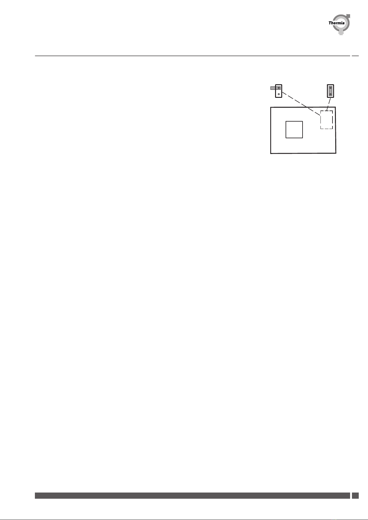
IMPORTANT! Requires Genesis software version 7.01 or later. Please note that a restart of the control system is required for the installa-
tion to establish communication between the heat pump and the Expansion module. This is indicated by the following icon in the dis-
play top bar (the same symbol is used in "Operating mode" in the display to execute a restart):
Installation Guide Expansion Module 3 (EM3)
ACEM301IG0502 Thermia AB
4

List of supported functions:
▪ID:1 TWC/WCS
▪ID:2 Distribution circuit 2 & 3
▪ID:3 Distribution circuit 4 & 5
▪ID:4 Cooling
▪ID:5 Pool
▪ID:10-17 Legacy (Jumper MUST be on both pins as shown in the picture to the right)
▪Control of internal brine pumps (only available with ID:1-5)
▪Start of external brine pump, 0-10V (Used with ID:1)
ID: 1-5 ID: 10-17
(+10)
0
1
23
4
6
78
9
5
Glossary for abbreviations printed on the EM-card:
▪X: Power supply (in and out, 230VAC)
▪R: Potential free relay
▪FR: Feeding relay (230VAC)
▪TR: TRIAC output (230VAC)
▪MBa1: ModBus communication in
▪MBa2: Modbus communication out
▪AO: Analogue out
▪CL: Current limiter
▪U: Universal input (analogue/digital)
▪D: Digital input
▪T: Temperature sensor input (PT1000)
▪Funktions ID: ID selector
▪MBa TERM: Termination jumper
Installation Guide Expansion Module 3 (EM3)
Thermia AB ACEM301IG0502 5

2 Components and dimensions
2.1 Components and hardware
Components included in kit:
1. EM3 card
2. Mounting screws EM3 card
3. Mounting plate (preinstalled in enclosure with spacer supports)
4. Screws for mounting plate
5. Enclosure
6. Mounting brackets
7. Screws for mounting brackets
8. Sealing plugs
9. Wiring decal
Required/optional components not included:
1. Enclosure connectors (optional)
2. Sealing plugs
3. Power and signal cables
Installation Guide Expansion Module 3 (EM3)
ACEM301IG0502 Thermia AB
6

3 Installation
3.1 General information
General information
The EM3 module can be installed internally inside the heat pump or externally in a separate enclosure.
Installation must be made in an indoor environment.
3.2 Internal installation
For internal installation of EM3, see the below picture of the electrical cabinet in the heat pump for correct placement.
Follow the instructions in the chapter regarding connecting power supply and Modbus communication to set up EM3 with the BM-card.
1. Placement for EM3
2. BM-card
3.3 External installation
Installation Guide Expansion Module 3 (EM3)
Thermia AB ACEM301IG0502 7

3.3.1 Enclosure
The enclosure can be mounted to the wall by putting the screws through the back plane of the enclosure (marked positions inside the
enclosure) or by using the mounting brackets on the corners of the enclosure.
1. Mounting plate
2. Screw
Installation Guide Expansion Module 3 (EM3)
ACEM301IG0502 Thermia AB
8

1. Enclosure
2. Knock out panel
3. Sealing plug
4. Screw
5. Sealing plug for screw holes
6. Mounting bracket
7. Screw for mounting bracket
If more than one enclosure is to be used for the installation it is possible to interconnect a number of enclosures with couplers (not
included).
1. Enclosure connector
Installation Guide Expansion Module 3 (EM3)
Thermia AB ACEM301IG0502 9

3.3.2 Wiring, mounting plate and EM3
1. Remove the knock out panels as required for routing the wiring into the enclosure.
2. Put sealing plugs on the cables and route all cables into the enclosure. Cut away the outer insulation layer on the cables just inside the
enclosure to facilitate easier routing and connection ot the wires to the EM3 unit terminals. Make sure you leave enough wire length
inside the enclosure to ensure tension free connections on the EM3 terminals and press the sealing plugs into the holes in the enclosure.
A. Cut the outer insulation just inside of the enclosure.
B. Leave enough wire length to ensure tension free connections.
3. Fit the EM3 unit onto the plastic PCB spacer supports on the mounting plate and press down on the EM3 unit so that the spacer
supports locks on to the circuit board. Secure the EM3 unit to the mounting plate with the two screws.
1. EM3 unit
2. Screw
Installation Guide Expansion Module 3 (EM3)
ACEM301IG0502 Thermia AB
10

4. The function switch in the center of the EM3 unit is by default set to the 0 (zero) position and the jumper switch to the right of it is set
to open position (jumper is not mounted on both pins).
Only in Legacy configurations (ID:10-17) should the jumper be mounted on both pins!
Make sure the function switch correlates with the same ID number as the respective function that is configured with the EM3. Connect
the power supply wires between X54-X56 (EM3) and X13-X15 (BM-card). Connect the Modbus wires between MBa1 (EM3) and Ex-
pansion Mba2 (BM-card) as shown in the picture below.
In the event of more than one EM3-card active in the same installation, connect the communication wires from MBa2 (EM3) on the first
card to MBa1 (EM3) on the second card, etc. As shown in the picture below.
Installation Guide Expansion Module 3 (EM3)
Thermia AB ACEM301IG0502 11

5. Termination of a communication network is needed whenever the Modbus connection is used. This to ensure that the receiver is
getting the maximum signal power, by matching the characteristic impedance of the cabling using termination jumpers on each end of
the communication network.
Below is a schematic example of a series of accessories and where to put the termination jumpers accordingly:
MBa-
MBa+
GND
MBa-
MBa+
GND
MBa-
MBa+
GND
MBa-
MBa+
GND
MBa-
MBa+
GND
MBa-
MBa+
GND
BM-Card EM3-TWC/WCS EM3-Cooling
Termination Termination
EM3-Pool EM3-Legacy 1 EM3-Legacy 2
Locate the termination jumper on the EM3-card from the below picture:
EM3
U94U93U92U91 T87T86T85T84T83T82T81
24AC
+ -
+ -
+ -+ -
(out) (in)
GND
D-
D+
24AC
0-10
GND
24AC
0-10
GND
Y N L1 Y N L1 L NL NL N
NN N
L1 L1 L1
2 3 GND
1
CL1
Y
X56
X55
AO73AO72
0
1
23
4
6
78
9
5
L N
N
L1
N L1
GND
0-10
24AC
D+
D-
GND
MBa2 MBa1
TR67 FR61FR62FR63FR64TR65
TR66
D95 D96
R53
AO71
R52
R51 X54
The jumper is activated on the EM3-card
The jumper is NOT activated on the EM3-card
Installation Guide Expansion Module 3 (EM3)
ACEM301IG0502 Thermia AB
12

4 Supported functions
4.1 Supported functions
4.1.1 Function ID: 1, TWC/WCS
TWC
75 63
31 56
53
180
115
111
184
24AC
T81T82 T83 T84 T85 T86 T87
(out) (in)
GND
D-
D+
GND
0-10
24AC
+
U91
-
U
+
92
-+
U9
-
3
+
U94
-
0-10
24AC
GND
Y N L1 Y N L1 L NL NL N
2 3
NN N
GND1
L1L1 L1
Y
CL1
X56
X55
0
AO72 AO73
1
23
4
6
78
9
5
N
L1
L N
GND
NL1
D+
0-10
24AC
D-
GND
MBa2 MBa1
FR61
TR67 FR62FR63FR64TR65
TR66
R53
AO71
R52
D95D96
R51 X54
EM3
EM3
Installation Guide Expansion Module 3 (EM3)
Thermia AB ACEM301IG0502 13

TWC
Table item number Terminal Description TWC
31 FR61 Circulation pump (HWC) X
56 T82 Sensor HWC return line X
63 T81 Sensor hot water X
75 AO71 Mixing valve HW X
115 R51 Auxiliary heater hot gas boiler X
180 T83 Tank sensor TWC (hot gas boiler) X
184 TR65 Reversing valve hot gas boiler X
TWC - Tap Water Control
The TWC function regulates the temperature in the end tank and the outgoing hot water (mixing valve (75) is required).
The mixing valve keeps the desired set value on the outgoing hot water.
An auxiliary heater (115) can be activated/deactivated if the temperature in the end tank (180) goes above or under the set value.
The HWC circulation pump (31) is in constant drive and the Sensor HWC return line (56) is used only for monitoring.
TWC with hot gas functionality
This function is used to switch the hot gas charge (184) between the end tank and the storage tank (requires an installed hot gas pump
and that hot gas is activated in the display).
When the temperature in the end tank exceeds the set value (default 80°C), the storage tank is connected.
The mixing valve switches back if:
▪the end tank goes below 70°C
▪or if the temperature goes below the stop temperature for TWC + 3°C (to avoid starting the auxiliary heater)
▪or if the temperature in the storage tank gets higher than 85°C
Commission after installation:
1. Login: Press padlock, 607080 and confirm
2. Go to SETTINGS/INSTALLATION and activate TWC and Hot Gas
3. Go to SETTINGS/TWC and enable TWC
4. Go to SETTINGS/HOT GAS and enable Hot gas and directional valve function
Installation Guide Expansion Module 3 (EM3)
ACEM301IG0502 Thermia AB
14

5. Make desired settings and save
6. Restart the heat pump and check functionality
TWC - Antilegionella
With the TWC the antilegionella function is scheduled to activate the auxiliary heater in the end tank, whenever the demand for antile-
gionella is active.
Commission after installation:
1. Login: Press padlock, 607080 and confirm
2. Go to SETTINGS/INSTALLATION and activate TWC
3. Go to SETTINGS/TWC and turn on function
4. Make desired settings and save
5. Restart the heat pump and check functionality
Installation Guide Expansion Module 3 (EM3)
Thermia AB ACEM301IG0502 15

WCS - Water Charge System
35
73
54
46
111
24AC
T81T82T83 T84 T85 T86 T87
(out) (in)
GND
D-
D+
GND
0-10
24AC
+
U91
-
U
+
92
-+
U9
-
3
+
U94
-
0-10
24AC
GND
YN L1 YN L1 L NL NL N
23
NN N
GND1
L1L1 L1
Y
CL1
X56
X55
0
AO72 AO73
1
23
4
6
78
9
5
N
L1
L N
GND
NL1
D+
0-10
24AC
D-
GND
MBa2 MBa1
FR61
TR67 FR62FR63FR64TR65TR66
R53
AO71
R52
D95D96
R51 X54
EM3
EM3
Installation Guide Expansion Module 3 (EM3)
ACEM301IG0502 Thermia AB
16

WCS
Table item number Terminal Description WCS
35 FR62 Circulation pump (WCS) X
54 T86 Sensor (WCS) X
73 AO72 Control valve WCS X
343 U94 External WCS start X
WCS - Water Charge System
The WCS function controls the hot water tank charge temperature by regulating the return line temperature (54) when hot water pro-
duction is active. When hot water production is active the circulation pump (35) will run and the mix valve will regulate the return line
temperature (54) according to the desired temperature setpoint. The valve will close if the temperature at (54) drops and reversed if the
temperature rises. Minimum opening degree for the Control valve WCS (73) is set default to 15% and can be changed in the display.
Commission after installation:
1. Login: Press padlock, 607080 and confirm
2. Go to SETTINGS/INSTALLATION and activate WCS
3. Go to SETTINGS/WCS and turn on function
4. Make desired settings and save
5. Restart the heat pump and check functionality
WCS with hot gas circuit
The WCS hot gas function is used for charging the hot water with the hot gas circuit when a regular hot water tank production does not
run. The WCS function starts when a hot gas pump is running. In a primary/secondary system solution the hot gas pumps on the secon-
daries are also considered. The WCS function stops when all hot gas pumps in the system has stopped running.
Commission after installation:
1. Login: Press padlock, 607080 and confirm
2. Go to SETTINGS/INSTALLATION and activate WCS
3. Go to SETTINGS/INSTALLATION and activate Hot gas
4. Go to SETTINGS/HOT GAS and enable Hot gas
5. Go to SETTINGS/WCS and enable WCS and turn on the WCS hot gas function
6. Make desired settings and save
7. Restart the heat pump and check functionality
Installation Guide Expansion Module 3 (EM3)
Thermia AB ACEM301IG0502 17

WCS and TWC (with hot gas functionality)
75
35
73
54
63
31
56
111
184
180
115
24AC
T81T82T83 T84 T85T86 T87
(out) (in)
GND
D-
D+
GND
0-10
24AC
+
U91
-
U
+
92
-+
U9
-
3
+
U94
-
0-10
24AC
GND
Y NL1 Y N L1 L NL NL N
2 3
NN N
GND1
L1L1 L1
Y
CL1
X56
X55
0
AO72 AO73
1
23
4
6
78
9
5
N
L1
L N
GND
NL1
D+
0-10
24AC
D-
GND
MBa2 MBa1
FR61
TR67 FR62FR63FR64TR65
TR66
R53
AO71
R52
D95D96
R51 X54
EM3
EM3
Installation Guide Expansion Module 3 (EM3)
ACEM301IG0502 Thermia AB
18

WCS and TWC
Table item number Terminal Description
31 FR61 Circulation pump (HWC)
35 FR62 Circulation pump (WCS)
48 T84 Sensor external brine in
49 T85 Sensor external brine out
54 T86 Sensor (WCS)
56 T82 Sensor HWC return line
63 T81 Sensor hot water
73 AO72 Control valve WCS
75 AO71 Mixing valve HW
115 R51 Auxiliary heater hot gas boiler
172 R52 Auxiliary circulation pump (brine)
172 AO73 Auxiliary circulation pump (brine)
176 R53 External heater burn out pump (Dynamic allocation I/O)
180 T83 Tank sensor TWC (hot gas boiler)
184 TR65 Reversing valve hot gas boiler
343 U94 External WCS start
345 D95 Start internal brine
444 D96 External alarm (Dynamic allocation I/O)
WCS and TWC (with hot gas functionality)
WCS with hot gas charge and end tank (TWC).
Installation Guide Expansion Module 3 (EM3)
Thermia AB ACEM301IG0502 19

This function is used to charging hot water via the hot gas circuit into an end tank when ordinary hot water production is not active. The
hot gas circuit will charge the end tank as long as the temperature in the end tank has not reached the maximum allowed temperature
(adjustable in the display).
When the maximum allowed temperature is reached, the reversing valve for the hot gas boiler (184) shifts to charge the storage tank via
the WCS valve. When the valve for hot gas shifts, the WCS control starts to charge the storage tank with the hot gas circuit.
Functions needed to be activated:
▪WCS
▪TWC
▪WCS hot gas functionality (activated in the WCS menu in the display)
▪Hot gas (activated in the hot gas menu in the display)
Commission after installation:
1. Login: Press padlock, 607080 and confirm
2. Go to SETTINGS/INSTALLATION and activate WCS
3. Go to SETTINGS/INSTALLATION and activate TWC
4. Go to SETTINGS/INSTALLATION and activate Hot gas
5. Go to SETTINGS/WCS and enable WCS and turn on the WCS hot gas function
6. Go to SETTINGS/HOT GAS, enable Hot gas and activate Reversing valve hot gas enable
7. Make desired settings and save
8. Restart the heat pump and check functionality
Installation Guide Expansion Module 3 (EM3)
ACEM301IG0502 Thermia AB
20
Table of contents
Popular Control Unit manuals by other brands

Emerson
Emerson PENBERTHY N7 Series Installation, operation and maintenance instructions

Mitsubishi Electric
Mitsubishi Electric EMU4-CNT-MB user manual

Crestron
Crestron CWD6671 Operation guide

SSS Siedle
SSS Siedle ZDS 601-0 Product information

Johnson Controls
Johnson Controls MS-IOM3723 installation guide

ICP DAS USA
ICP DAS USA M-7069 quick start guide