Afag GMQ 12 RE-50 User manual

Rotary gripper pneumatic / electric
GMQ 12 / RE-50
GMQ 12 / RE-50 24V/48V
Declaration of Incorporation
Module Information
Mounting Instructions
Maintenance Instructions
„Translation“ of the Original Operating Instructions
© Copyright by Afag Automation AG

GMQ 12 RE-50-OI-vers. 1.2 gb. 28.07.2014
These operating instructions apply to:
Type Order No.
Type Order N0.
GMQ 12/K / RE-50 50394843
GMQ 12/P / RE-50 50394844
GMQ 12/P-01 / RE-50 50394846
GMQ 12/K / RE 50 24V/48V 50395566
GMQ 12/P / RE 50 24V/48V 50395567
GMQ 12/P-01 / RE-50 24V/48V 50395569
Assembly and initial start-up must be carried out by qualified personnel only and ac-
cording to these operating instructions.
Version of this
documentation:
GMQ 12 RE-50-OI-vers. 1.2 gb. 28.07.2014
Symbols:
DANGER
Indicates an immediate threatening danger.
Non-compliance with this information can result in death or se-
rious personal injuries (invalidity)
WARNING
Indicates a possible dangerous situation.
Non-compliance with this information can result in death or se-
rious personal injuries (invalidity)
CAUTION
Indicates a possibly dangerous situation.
Non-compliance with this information can result in damage to
property or light to medium personal injuries.
NOTE
Indicates general notes, useful operator tips and operating recom-
mendations which don’t affect safety and health of the personnel.
2

GMQ 12 RE-50-OI-vers. 1.2 gb. 28.07.2014 3
Table of Contents
1.0 EC Declaration for Incorporation .......................................................................5
2.0 Module Information.............................................................................................7
2.1 Safety....................................................................................................................7
2.2 Transport, handling, storage .................................................................................7
2.3 Module Description...............................................................................................7
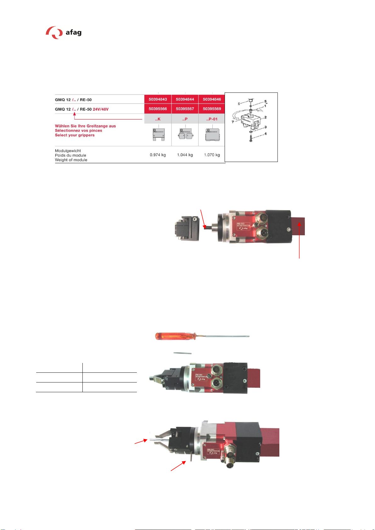
2.4 Nomenclature construction gripper rotary module GMQ 12 / RE-50……………. 8
2.5 GMQ 12 / RE-50 pneumatically /electric……………………………………………..9
2.6 Mounting of the gripping pliers………………………………………………………10
2.7 The gripper fingers are not included………………………………………………..11
2.8 Assembly connection.........................................................................................11
2.9 Tightening moments for screw.......................................................................... 13
2.10 Installation in a system .....................................................................................14
2.11 Turning the rotary module if the cable outlets don’t fit .....................................15
3.0 Mounting Instructions.....................................................................................17
3.1 Intended use.......................................................................................................18
3.2 Warranty.............................................................................................................19
3.3 Safety .................................................................................................................19
3.4 Dimensional drawing: GMQ 12 / RE-50..............................................................20
3.5 Technical data GMQ 12 / RE-50.........................................................................21
3.6 Graph of gripping forces eccentricity……………………………………………….22
3.7 Rotary modules RE-50 (without flange)………………………………………...…..23
3.8 Rotation time RE-50…………………………………………………………………..24
3.9 Technical data RE-50………………………………………….……………………..26
3.10 Electrical interface ...........................................................................................25
3.11 Commissioning, operation, training ..................................................................26
3.12 Preparation for commissioning .........................................................................27
3.13 Commissioning..................................................................................................28
3.14 Setting / Changeover........................................................................................28
3.15 Normal operation..............................................................................................29
4.0 Maintenance Instructions ................................................................................30
4.1 Servicing.............................................................................................................30

GMQ 12 RE-50-OI-vers. 1.2 gb. 28.07.2014
4.2 Further maintenance ...........................................................................................31
4.3 Possible failures ..................................................................................................32
4.4 Exchanging the gripper actuator (pneumatic or electric) ....................................33
4.5 Exchanging the RE-50 rotary module..................................................................35
4.6 End position sensor replacement .......................................................................36
4.7 Spare parts.........................................................................................................36
4.8 Accessories.........................................................................................................37
4.9 Extension and repair...........................................................................................38
5.0 Disposal..............................................................................................................38
4

GMQ 12 RE-50-OI-vers. 1.2 gb. 28.07.2014 5
1.0 EC Declaration for Incorporation
According to 2006/42/EC dated 09. June 2006, Appendix II B VI for
Incorporation of partly completed machinery.
The manufacturer: Afag Automation AG, Fiechtenstrasse 32, CH-4950 Huttwil
Tel. +41 62 959 87 02, www.afag.com
As manufacturer of the partly completed machine we declare that:
-The specified machine corresponds to the listed essential requirements of the
directive 2006/42/EG, wehere applicable the other directives and standards
listed below.
Designation:
Rotary gripper modules
(pneumatic / electric)
Types:
GMQ 12-RE-50
GMQ 12-RE-50 24V/48V
Sequential serial No.:
The actual serial number will be
sticked in here upon delivery of the device.
-Machinery Directive 2006/42/EC
-EMV-Guideline 2004/108/EC
-Production Safety Directive
2001/95/EG
-RoHS 2002/95/EC
-Low voltage Directive
2006/95/EC
-The relevant technical documentation is compiled in accordance with part B of
Annex VI
-The relevant technical documentation in accordance with part B of Annex VI
will be transmitted in response to a reasonable request by the national authori-
ties in printed from or in electronic from (pdf).
Notes to the Declaration of Incorporation according to the Machinery Di-
rective 2006/42/EC, Annex IIB, section 4.
(Checklist on accurate and basic health and safety requirements).
1.1; 1.1.1; 1.1.2; 1.2; 1.2.1; 1.2.3; 1.2.4.4; 1.2.5; 1.3; 1.3.3; 1.3.5; 1.3.6; 1.3.7;
1.3.8.1; 1.3.8.2; 1.3.9; 1.4.1; 1.5; 1.5.1; 1.6; 1.6.1; 1.6.3; 1.6.4; 1.7; 1.7.1; 1.7.4.;
1.7.4.1; 1.7.4.2; 1.7.4.3; 3.3.5; 3.4.1
-Increase of the harmonized standards applied:
-EN 349; EN ISO 12100-1; EN 12100-2; EN ISO 14121-1; EN 60204-1: 2006
-EN 61000-6-2; EN 61000-6-4

GMQ 12 RE-50-OI-vers. 1.2 gb. 28.07.2014
Name and address of the person authorised to compile the relevant technical docu-
mentation:
Lanz Beat, PM & Marketing-Services, Afag Automation AG
This partly completed machinery must not be put into service until the final machinery
into which it is to be incorporated has been declared in conformity with the provisions
of this Directive 2006/42/EC, where appropriate.
Place/Date: Huttwil, 28.07.2014
Markus Werro
Managing Director
Afag automation AG
Siegfried Egli
Head of HT
Afag automation AG
6

GMQ 12 RE-50-OI-vers. 1.2 gb. 28.07.2014 7
2.0 Module Information
2.1 Safety
Modifications to the rotary-gripper module that are not described in this operating
manual or have not been approved in writing by the company Afag Automation AG
are not permitted. In case of improper changes or assembly, installation, operation,
maintenance or repairs, Afag Automation AG rejects all liability.
2.2 Transport, handling, storage
For transport and storage, the following conditions must be met:
Temperature storage: 0-50°C
Humidity: <90%, non condensing
CAUTION
The rotary-gripper module is packed in the original box. In the
case of improper handling the module may drop out of the box
when it is unpacked and cause injuries to limbs.
NOTE
Please note!
A technical safety information sheet is enclosed with each module.
This information sheet must be read by every person who operates
the module.
2.3 Module Description
The rotary-gripper module is a very compact electrical / pneumatic rotary module
which is suitable for rotating useful loads (see Technical Data). The RE rotary mod-
ules are fitted with a 17-pole industrial connector (G13) and a 4-pole M15 connector.
The RE rotary modules are designed for operation with the Afag controllers SE-
Power 1kVA, SE-48 and SE-24. They can, however, also be operated with control-
lers of other manufacturers.

GMQ 12 RE-50-OI-vers. 1.2 gb. 28.07.2014
2.4 Nomenclature construction gripper rotary modules GMQ 12 / RE-50
(pneumatic / electric)
The new gripper-rotary module consists of the afag standard modules::
- Gripper actuator GMQ 12
- Rotary modules RE-50
- Gripper GMQ 12/..
Due to their compact construction the gripper-rotary modules dont’t have any
disturbing contours. (narrow design)
8

GMQ 12 RE-50-OI-vers. 1.2 gb. 28.07.2014 9
2.5 GMQ 12 RE-50 pneumatically / electric
1 Gripper 2 Servo drive with gears
3 Encoder housing 4 Proximity switch
5 Encoder connection 6 Motor connection
7 Adapter unit 8 Gripper actuator
9Connecting flange Figure 1: Module description
1
2
4
5
7
8
6
3
9

GMQ 12 RE-50-OI-vers. 1.2 gb. 28.07.2014
2.6 Mounting of the gripping pliers
Pliers can be retrofitted to rotary-gripper modules which were ordered without pliers.
The EG-20 gripper actuator can be fitted with the standard gripper pliers of the GMQ
20 pneumatic grippers. There are 3 different types available.
Mounting of the gripping pliers:
Extend the drawbar on the GMQ pliers actuator electrically when mounting the gripper pliers.
Disassembly of the gripper:
Extend the drawbar on the EG pliers actuator electrically when dismounting the gripper pliers
Procedure:
Material for assembly / disas-
sembly:
Allen screwdriver 3 mm
Cylinder pin Ø 2.5 x30 mm
Cylinder pin
Drawbar
GMQ-Gripper actuator
1 Centering bushings
2 Gripper
3 Disc
4 Mounting Screw
5 Centering
6 Drawbar
7 Clambing screw
Processure:
-Insert centering ring 5 and centering sleeve 1
-Insert cylinder pin in flange (fix)
-Push on gripper pliers 2
-Tighten screw 4
-Align gripper pliers, tighten clamping screw 7
10
Insert cylinder pin in the flange
holes so that the gripper pliers is
locked.
Loosen screw using the Allen
screwdriver.
GMQ 12/K
Socket SW 5,5
GMQ 12/P
Socketl SW 5,5
GMQ 12/P-01
Allen key SW 2,5

GMQ 12 RE-50-OI-vers. 1.2 gb. 28.07.2014 11
2.7 The gripper fingers are not included!
It’s the customer’s responsibility to manufacture the gripper fingers. The jaws of the
gripper pliers are provided with a default seat (6H7) for this.
The drawings of the pliers are included in the Technical Catalogue.
NOTE
The gripper fingers are not part of the delivery and must be manufac-
tured by the user of the rotary-gripper module.
2.8 Assembly connection
WARNING
Due to the rotating movement of the gripper pliers, hair or other
materials may be caught and drawn into the system while the
module is being operated.
Caution: Commissioning may only be executed by qualified
personnel.
Drawbar
Loosen clamping screw at the
gripper pliers. The pliers head can
be removed
New gripper pliers can now be
mounted on the rotary gripper.
Procedure:
Please see „Mounting of the grip-
per pliers“

GMQ 12 RE-50-OI-vers. 1.2 gb. 28.07.2014
WARNING
Always switch off the controller and protect it against being
switched on again unintentionally when you work on the rotary-
gripper module. The signals of the control system may cause
unintentional movements of the module which may lead to per-
sonal injuries.
The rotary-gripper module can be mounted in a vertical or horizontal position.
The rotary-gripper module can be fastened to the black intermediate piece (grid of 30
x 30 mm), using 4 M4 screw.
Acreade:
Use the centring sleeves included in the scope of delivery for positioning and insert
these sleeves in the diagonally opposite bore holes of the mounting grid.
12
Fixing grid 30x30mm
4xØ4,5mm can be tapped
Fixing grid Ø58mm, 4x
Ø3,4mm can be tapped
Squaring Ø49h7 for flange
mounting
Mounting thread 2xM3 (e.g.
for hold-down)

GMQ 12 RE-50-OI-vers. 1.2 gb. 28.07.2014 13
2.9 Tightening moments for screw
The screws to be used for assembly must at least satisfy the following conditions:
Standard: VDI 2230
Strength: class 8.8
Surface: galvanized blue, oiled or greased
Thread
Tightening moments
M2
M2.5
M3
0,3 … 0,35 Nm
0,5 … 0,73 Nm
1,1 … 1,4 Nm
M4
2,6 … 3,3 Nm
M5
5,2 … 6,5 Nm
M6
9,0 ... 11,3 Nm
M8
21,6 ..27,3 Nm
Table 1: Tightening moments for screw

GMQ 12 RE-50-OI-vers. 1.2 gb. 28.07.2014
2.10 Installation in a system
DANGER
The gripper rotary engine may not be used in hazardous envi-
ronments.
WARNING
If add-ons at the rotary-gripper module could cause danger in
connection with moving parts a safe operation must be en-
sured.
Ensure that the operator cannot reach into the operating range
of the rotary-gripper module during normal operation.
Ensure that there is no danger to the operator of the system in
special operating modes. The concept depends on the safety
concept of the system and the attached machine parts.
WARNING
Due to the decentral controller the operator of the rotary-gripper
module needs not to be near the product so that third persons
might be endangered by the rotation mode.
Lock the controller while you are working on the rotary-gripper
module and switch the controller only on again after work is
finished.
CAUTION
The rotary-gripper module is a partly complete machine.
The rotary-gripper module must be integrated in the safety con-
cept of the system so that a safe operation can be ensured.
Ensure that the operating personnel cannot reach into the op-
erating range of the rotary-gripper modules during operation.
The rotary-gripper module may only be used in accordance with
the intended purpose.
Ensure that the operator cannot reach into the operating range
of the rotary-gripper module during normal operation. This can
be achieved by taking appropriate safety measures such as
casings, a light grid or by disconnecting the system from the
power supply.
14

GMQ 12 RE-50-OI-vers. 1.2 gb. 28.07.2014 15
NOTE
This operating manual should be read carefully before carrying out
any activity on or with the rotary-gripper module.
2.11 Turning the rotary module if the cable outlets don’t fit
In the delivery state the cable connections on the rotary module are facing forward.
You can turn the black mounting part so that the cable outlets are pointing to the left
or right side. Please proceed as follows:
Selectable cable outlet:
Gripper actuator GMQ: Every
possible position 360°
RE-50 rotary module: 4 Po-
sition each 90° possible

GMQ 12 RE-50-OI-vers. 1.2 gb. 28.07.2014
Procedure:
Loosen 4 screws on the RE-50
using the 2.5 mm allen screw-
driver
Remove the RE-50 turn to the
desired side and remount.
Bolt down the RE-50 in the new
position.
16

GMQ 12 RE-50-OI-vers. 1.2 gb. 28.07.2014 17
3.0 Mounting Instructions
Manufacturer address: Afag Automation AG
Fiechtenstrasse 32
CH-4950 Huttwil
Sales Handling:
Tel. +41 62 959 87 02
www.afag.com
Product name: Rotary gripper module (pneumatic / electric)
Types: GMQ 12 / RE-50
GMQ 12 / RE-50 24V/48V
This is an incomplete machine
This partly completed machinery must not be put into service until the final machinery
into which it is to be incorporated has been declared in conformity with the provisions
of this Directive 206/42/EG, Annex II B IV where appropriate.
Name and address of the person authorised to compile the relevant technical docu-
mentation: Lanz Beat, PM & Marketing-Services, Afag Automation AG

GMQ 12 RE-50-OI-vers. 1.2 gb. 28.07.2014
3.1 Intended use
The rotary-gripper modules are used for the smooth rotary movement of loads in
non-explosion hazardous ambient and operating conditions that are specified for this
module (see Technical Data).
The rotary-gripper modules are exclusively intended for rotating useful loads (see
Technical Data) which do neither impair the safety of persons nor present a danger
to property and the environment. Combined with other modules they can be used as
a pick & place station.
NOTE
Any use that exceeds the use mentioned above is regarded as im-
proper.
The manufacturer does not accept any liability for damage resulting
from such use. The risk is that of the user alone.
Intended use also includes paying attention to the operating manual and observing
the maintenance and repair instructions specified by the manufacturer.
CAUTION
The rotary-gripper module may only be operated and serviced
by correspondingly trained personnel who have also profound
knowledge of the dangers.
The applicable regulations for prevention of accidents and the
other generally accepted safety-relevant and occupational safe-
ty and health regulations are to be followed.
18

GMQ 12 RE-50-OI-vers. 1.2 gb. 28.07.2014 19
3.2 Warranty
The rotary-gripper module is designed for 40 million load changes / 2 years opera-
tional performance under the ambient and operating conditions defined for this mod-
ule (see “Technical data”). Load data and design- and acceleration diagrams must be
observed.
There are no wearing parts for the rotary-gripper module!
The warranty includes the replacement or repair of defective module parts at Afag
Automation AG.
When repairs are carried out by the customer without prior training or instruction from
Afag Automation AG the warranty will become void. Any use which exceeds the in-
tended purpose will result in the warranty becoming null and void.
Any additional claims are excluded.
3.3 Safety
This operating manual should be read carefully before carrying out any activity on or
with the module. The module may only be deployed in accordance with the intended
use. Modifications on the module that are not described in this operating manual or
have not been approved in writing by Afag are not permitted. In the case of improper
changes or assembly, installation, operation, maintenance or repairs, Afag AG re-
jects all liability.
CAUTION
Connection of a control system and operation of the rotary-gripper
module can lead to unpredictable movements which may result in
personal injury or damage to property.

GMQ 12 RE-50-OI-vers. 1.2 gb. 28.07.2014
3.4 Dimensional drawing: GMQ 12 / RE-50
Figure 2: Dimension drawing GMQ 32-RE-50
20
This manual suits for next models
8
Table of contents
Other Afag Control Unit manuals
Popular Control Unit manuals by other brands

Interlogix
Interlogix ATS1520 Installation sheet

Bardiani
Bardiani BBZS1 Instruction, use and maintenance manual

Automationdirect.com
Automationdirect.com Productivity 2000 P2-16TR manual

Sav
Sav SAV 876.10 operating instructions

Siemens
Siemens VVF Series Mounting instructions

E-T-A
E-T-A EM12D-TMB Series installation manual