Thermia MBH Series User manual

Thermia Värmepumpar is not liable or bound by warranty if these
instructions are not adhered to during installation or service.
The English language is used for the original instructions.
Other languages are a translation of the original instructions.
(Directive 2006/42/EC)
© Copyright Thermia Värmepumpar

Table of Contents
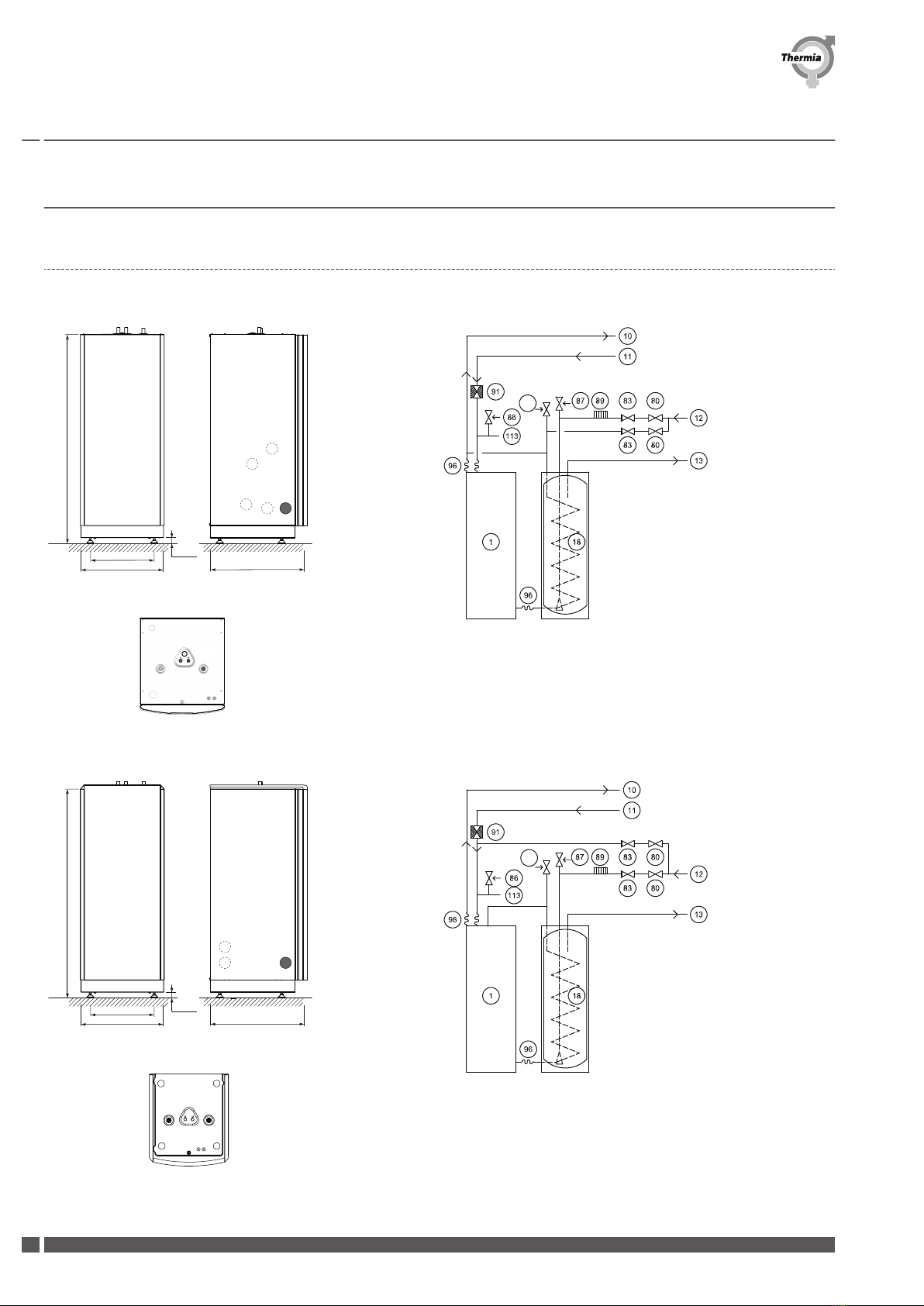
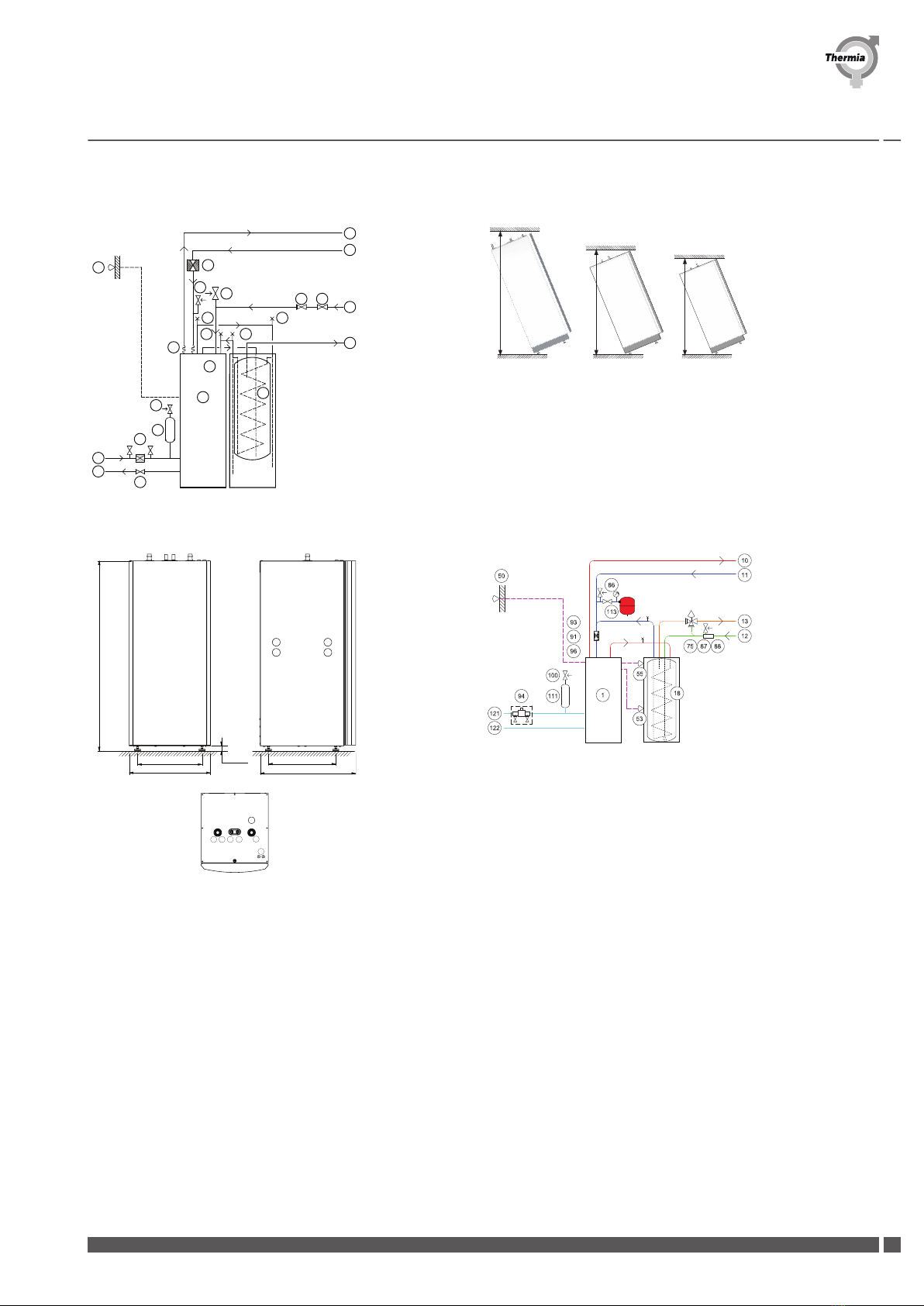
1 Connections and dimensions ........................................................ 4
1.1 Connections and dimensions ..................................................... 4
2Svenska, Installation .............................................................. 6
2.1 Installation ................................................................. 6
2.1.1 Produktbeskrivning ............................................................ 7
2.1.2 Anslutningar och mått .......................................................... 7
2.1.3 Montering .................................................................. 7
2.1.4 Placering ................................................................... 7
2.1.5 Rörinstallation ............................................................... 8
2.2 Skötsel .................................................................... 8
2.2.1 Säkerhetsventil ............................................................... 8
2.2.2 Vattenkvalitet ............................................................... 9
2.2.3 Givare .................................................................... 9
2.2.4 Installation utförd av: ........................................................... 10
3 English, Installation ............................................................... 11
3.1 Installation ................................................................. 11
3.1.1 Product description ............................................................ 12
3.1.2 Connections and dimensions ..................................................... 12
3.1.3 Installation ................................................................. 12
3.1.4 Positioning ................................................................. 12
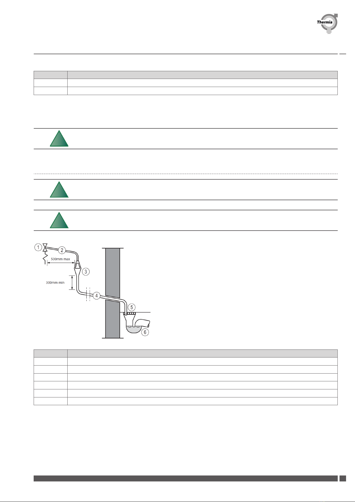
3.1.5 Piping installation ............................................................. 13
3.2 Maintenance ................................................................ 14
3.2.1 Safety valve ................................................................. 14
3.2.2 Water quality ................................................................ 14
3.2.3 Sensors .................................................................... 14
3.2.4 Installation carried out by: ....................................................... 15
3.2.5 UK-specific appendix ........................................................... 16
4 Deutsch, Installation .............................................................. 21
4.1 Installation ................................................................. 21
4.1.1 Produktbeschreibung .......................................................... 22
4.1.2 Anschlüsse und Maße .......................................................... 22
4.1.3 Montage ................................................................... 22
4.1.4 Aufstellung ................................................................. 22
4.1.5 Rohrinstallation .............................................................. 23
4.2 Wartung ................................................................... 24
4.2.1 Sicherheitsventil .............................................................. 24
4.2.2 Wasserqualität ............................................................... 24
4.2.3 Fühler .................................................................... 25
4.2.4 Installation wurde ausgeführt durch: ................................................. 25
Installation Guide MBH
Thermia Värmepumpar 086L5801 3

1 Connections and dimensions
1.1 Connections and dimensions
1. 3.
455
596 690
40 ±10
1
2 3 4
5
6
H
118
2. 4.
455
596 690
40 ±10
H
1
2 3 4
5
6
118
Installation Guide MBH
086L5801 Thermia Värmepumpar
4

5. 6.
91
87
85
96
1
85
19
85
85
50
100
111
94
80
13
12
121
122
80
83
10
11
150
86
1905
1620
MBH 300
MBH 200 H
MBH 200
1550
MBH 200
Inverter Mini
7. MBH Inverter Mini 8. MBH Inverter Mini
H
40 ± 10
474
702,6
495
598
162 3 4
5
Installation Guide MBH
Thermia Värmepumpar 086L5801 5

2 Svenska, Installation
2.1 Installation
Warning Den här enheten kan användas av barn över 8 år och personer med
nedsatt fysisk, sensorisk eller psykisk förmåga, eller av personer som
saknar kunskap eller erfarenhet, förutsatt att de övervakas eller har fått
instruktioner om hur enheten ska användas på ett säkert sätt och för-
står vilka risker som föreligger. Barn får inte rengöra eller utföra använ-
darunderhåll på enheten utan att stå under uppsikt av en vuxen.
N
Rörinstallationen skall utföras enligt gällande lokala regler och förord-
ningar. Varmvattenberedaren skall förses med godkänd säkerhetsven-
til (bipackad).
N
Beredaren ska anslutas till expansionskärl och säkerhetsventil på så-
dant sätt att det ej går att stänga av denna förbindelse.
N
Eftersom varmvattentemperaturen i Diplomat Optimum G2/G3, Diplo-
mat Duo Optimum G2/G3 och Diplomat Inverter L/M blir mycket hög
krävs att en blandningsventil installeras mellan kallvatten och var-
mvattenledningarna som säkerställer en lägre temperatur på tapp-
vattnet.
N
Se till att rörinstallationen utförs i enlighet med mått- och anslutnings-
skisserna.
N
Det är viktigt att värmesystemet är avluftat efter installation. Avluft-
ningsfilter monteras där så erfodras.
N
Vid demontering av produkten skall rådande lagar och regler beaktas.
Kontakta din installatör för mer information.
Installation Guide MBH
086L5801 Thermia Värmepumpar
6

2.1.1 Produktbeskrivning
Thermia MBH är moderna och effektiva förrådsberedare med ett mycket brett användningsområde för varmvattenproduktion. Varmvat-
tenberedare Thermia MBH är specialdesignade för att komplettera Thermia värmepumpar (G2 Design, G3 Design, Inverter Design och
Inverter Mini Design). Varmvattenberedaren används i anläggningar där hetvatten produceras av annan värmekälla - valfria energiform-
er kan därmed tas i anspråk. Varmvattenberedare är konstruerad enligt Pressure Equipment Directive / Tryckkärlsdirektivet 2014/68/EU
artikel 4.3
2.1.2 Anslutningar och mått
För Thermia MBH 200 (inkl. G2/G3 design samt Inverter design), se figur 1.
För Thermia MBH 300/MBH H 200 (inkl. G2/G3 design samt Inverter design), se figur 2
För Thermia MBH 200 Inverter Mini Design, se figur 7
Teckenförklaring
1. Returledning till värmekälla Ø 22 mm ( Ø 28 mm för MBH Inverter Mini Design )
2. Varmvatten Ø 22 mm
3. Kallvatten Ø 22 mm
4. Inlopp från värmekälla Ø 22 mm ( Ø 28 mm för MBH Inverter Mini Design )
5. Genomföringar
6. Avluftning
Varmvattenberedare MBH 200 Inverter Mini Design MBH 200 MBH H 200 MBH 300
Volym V 171,9 171,9 171,9 280,0
Beräkn. tryck Sek/prim, Mpa 1.0/0.3 1.0/0.3 1.0/0.3 1.0/0.3
Test tryck Sek/prim, Mpa 1.43/0.43 1.43/0.43 1.43/0.43 1.43/0.43
Vikt tom, kg 77 84,5 92 105
Vikt fylld, kg 267 285 300 410
Höjd, H*, mm 1398 1538 1845 1845
Varmhållningsförlusten S 59,3 59,3 59,3 91,7
Energieffektivitetsklass C C C C
2.1.3 Montering
1. Lossa frontplåten genom att vrida låsningen 90° moturs. Håll samtidigt emot frontplåten med handen.
2. Luta frontplåten utåt
3. Lyft frontplåten uppåt för att lossna den från varmvattenberedaren
2.1.4 Placering
• Placera Thermia MBH på ett golv som klarar vikten.
• Rummet skall vara försett med golvbrunn.
• Thermia MBH är avsedd för stående montage.
• För minsta takhöjd för resning av beredaren, se figur 6.
• Varmvattenberedaren ställs upp och därefter görs rörinstallationen. Ska beredaren monteras tillsammans med en värmepump ska
den placeras brevid värmepumpen och anslutas med en flexibel anslutningsledning
(gäller ej Inverter Mini).
Installation Guide MBH
Thermia Värmepumpar 086L5801 7

2.1.5 Rörinstallation
Exempel på inkoppling av Diplomat Duo Optimum och MBH, se figur 3.
Exempel på inkoppling av Diplomat Duo Optimum G2/G3 och MBH, se figur 4.
Exempel på inkoppling av Diplomat Optimum och MBH H 200, se figur 5.
Exempel på inkoppling av Diplomat Duo Inverter Mini och MBH 200 Inverter Mini design, se figur 8.
Teckenförklaring
1. Värmepump
10. Framledning
11. Returledning
12. Kallvatten
13. Varmvatten
18. Varmvattenberedare MBH
19. Varmvattenberedare MBH H 200
50. Utegivare
53. Nedre varmvattengivare
55. Övre varmvattengivare
75. Shuntventil HW
80. Avstängningsventil
83. Backventil
85. Avluftningsventil
86. Säkerhetsventil expansion värmesystem 1,5 bar
87. Säkerhetsventil kallvatten 9 bar (ingår i bipack)
89. Vakumventil
91. Smutssil (ingår i bipack)
94. Påfyllningskoppel
96. Flexslang (ingår i bipack)
100. Säkerhetsventil 1,5 bar
111. Avluftning och expansionskärl (köldbärare)
113. Expansion värmesystem
118. Säkerhetsventil 2,5 bar (varmvatten, drift)
121. Brine in
122. Brine ut
150. Connector
Kall- och varmvattenledning samt spilledning från säkerhetsventil ska utföras i värmebeständigt och korrosionssäkert material t ex kop-
par. Säkerhetsventilens spilledning ska stå i oavstängbar förbindelse med avlopp och mynna synligt över detta i frostfri miljö.
2.2 Skötsel
2.2.1 Säkerhetsventil
Säkerhetsventilen är ett skydd mot övertryck i den slutna varmvattenberedaren och ska därför ägnas regelbunden tillsyn.
• Kontroll av säkerhetsventilen görs genom att hatten vrids varvid ventilen ska släppa ut litet vatten via spilledningen. Detta bör göras
minst fyra gånger per år.
• Om ventilen ej fungerar ska den bytas.
Installation Guide MBH
086L5801 Thermia Värmepumpar
8

• Om säkerhetsventilen ej kontrolleras regelbundet föreligger risk att varmvattenberedaren skadas.
• Det är normalt att säkerhetsventilen under uppladdning av varmvattenberedaren släpper ut små mängder vatten, speciellt efter
större varmvattentappning. Ventilens öppningstryck är ej omställbart.
• Säkerhetsventilen ska vara placerad på kallvatteninloppet och monteras horisontellt med utlopp nedåt.
2.2.2 Vattenkvalitet
Denna produkt och dess komponenter är utvecklade för att fungera pålitligt och effektivt med vattenkvaliteter som uppfyller kraven i
VDI 2035. I praktiken innebär detta att vissa allmänna försiktighetsåtgärder bör vidtas:
Ett värmesystem innehåller ofta små mängder korrosionspartiklar (rost) och slam från kalciumoxid, och det bör alltid vidtas försiktighet-
såtgärder som ser till att vattnet i värmesystemet är så rent som möjligt. På så sätt säkerställs att systemet blir så hållbart och pålitligt
som möjligt. Om magnetit kan förväntas finnas i värmesystemet bör man alltid överväga rengöring av systemet och/eller installation av
magnetitfilter. Eventuella filter som medföljer värmepumpen ska alltid installeras. Smutssilen ska monteras på returledningen från vär-
mesystemet, så nära värmepumpen som möjligt.
Föroreningar av kemikalier och/eller olja ska alltid undvikas.
I områden med exceptionella vattenförhållanden vad gäller hårt vatten kan ett avhärdningsfilter vara nödvändigt att använda/installera
(gäller värmesystem, varmvatten och köldbärarkrets). Avhärdningsfiltret gör vattnet mjukare, avlägsnar föroreningar och förebygger kal-
kutfällning.
Den indirekta uppvärmningen av förbrukningsvarmvattnet är en fördel som gör Thermia MBH lämpliga i områden med kalkhaltigt vat-
ten. I anläggning där vattnet kommer från egen brunn bör kontroll ske att vattenkvaliteten inte kan ge upphov till skador i varmvatte-
ninstallationen.
• Rostfri behållare och rör bör inte utsättas för vatten med höga kloridhalter.
N
Vid mycket dålig vattenkvalitet bör vattenfilter installeras i anläggnin-
gen. En vattenanalys ger besked om eventuellt nödvändiga åtgärder.
2.2.3 Givare
Monteras Thermia MBH i kombination med Diplomat Duo Optimum eller Diplomat Duo Optimum G2/G3 skall givarna (NTC-typ) som
finns i beredaren anslutas på följande plintar:
• Nedre varmvattengivare – 311-312
• Övre varmvattengivare – 325-326
Monteras Thermia MBH Inverter i kombination med Diplomat Duo Inverter skall givarna (PT 1000 typ) som finns i beredaren anslutas på
följande plintar (X2):
• Nedre varmvattengivare – 16-17
• Övre varmvattengivare – 18-19
Monteras Thermia MBH Inverter Mini Design i kombination med Diplomat Duo Inverter Mini skall givarna (PT 1000 typ) som finns i bere-
daren anslutas på följande positioner på det inbyggda kortet i värmepumpen:
Installation Guide MBH
Thermia Värmepumpar 086L5801 9

• Nedre varmvattengivare – Y605 (Mid)
• Övre varmvattengivare – Y605 (Top)
2.2.4 Installation utförd av:
Rörinstallation:
Datum . . . . . . . . . . . . . . . . . . . . . . . . . . . . . . . . . . . . . . . . . . . . . . . . .
Företag . . . . . . . . . . . . . . . . . . . . . . . . . . . . . . . . . . . . . . . . . . . . . . . . .
Namn . . . . . . . . . . . . . . . . . . . . . . . . . . . . . . . . . . . . . . . . . . . . . . . . . .
Tel. nr . . . . . . . . . . . . . . . . . . . . . . . . . . . . . . . . . . . . . . . . . . . . . . . . . . .
Elinstallation:
Datum . . . . . . . . . . . . . . . . . . . . . . . . . . . . . . . . . . . . . . . . . . . . . . . . .
Företag . . . . . . . . . . . . . . . . . . . . . . . . . . . . . . . . . . . . . . . . . . . . . . . . .
Namn . . . . . . . . . . . . . . . . . . . . . . . . . . . . . . . . . . . . . . . . . . . . . . . . . .
Tel. nr . . . . . . . . . . . . . . . . . . . . . . . . . . . . . . . . . . . . . . . . . . . . . . . . . . .
Om denna anvisning ej följs vid installation, drift och skötsel är Thermia Värmepumpar åtagande enligt gällande garantibestämmelser ej
bindande. Thermia Värmepumpar förbehåller sig rätten till ändringar i detaljer och specifikationer utan föregående meddelande.
Installation Guide MBH
086L5801 Thermia Värmepumpar
10

3 English, Installation
3.1 Installation
Warning This appliance can be used by children aged 8 years and above, and
by persons with reduced physical, sensory or mental capabilities or
lack of experience or knowledge, provided that they are supervised or
have been instructed in the safe use of the appliance and understand
the hazards involved. Children must not clean or carry out user main-
tenance on the appliance except under adult supervision.
N
Piping installation must be carried out in accordance with applicable
local rules and regulations. The hot water tank must be equipped with
an approved safety valve (supplied).
N
The tank must be connected to an expansion tank and safety valve in
such a way that the connection cannot be shut off.
N
The highest permitted temperature in the MBH tanks is 100°C, both on
the secondary and primary side.
N
As the water temperature in Diplomat Optimum G2/G3, Diplomat Duo
Optimum G2/G3 and Diplomat Inverter L/M becomes extremely hot, a
mixing valve must be installed between the cold water and hot water
pipes to ensure a lower domestic hot water temperature.
N
It is important that the heating system is bled after installation. Bleed
filters must be installed where necessary.
N
Ensure that the pipe installation is carried out in accordance with the
dimensions and connection diagrams.
N
When disassembling the product, applicable laws and regulations
must be observed. Contact your installer for more information.
Installation Guide MBH
Thermia Värmepumpar 086L5801 11

3.1.1 Product description
Thermia MBH are modern and efficient storage tanks with a very wide range of uses for hot water production. Hot water heaters Thermia
MBH are specially designed to complement Thermia heat pumps. (G2 Design, G3 Design, Inverter Design and Inverter Mini Design) The
hot water tank is used in installations where the hot water is produced by another heat source – any energy forms can therefore be used
with it. The hot water tank is designed according to Pressure Equipment Directive 2014/68/EU article 4.3
3.1.2 Connections and dimensions
For Thermia MBH 200 (incl. G2/G3 design and Inverter design), see figure 1.
For Thermia MBH 300 / MBH H 200 (incl. G2/G3 design and Inverter design), see figure 2.
For Thermia MBH Inverter Mini Design, see figure 7.
Symbol explanation
1. Return pipe to heat pump Ø 22 mm ( Ø 28 mm for MBH Inverter Mini Design )
2. Hot water Ø 22 mm
3. Cold water Ø 22 mm
4. Inlet from heat source Ø 22 mm ( Ø 28 mm for MBH Inverter Mini Design )
5. Lead-ins
6. Venting
Water heaters MBH Inverter Mini Design MBH 200 MBH H 200 MBH 300
Volume V 171,9 171,9 171,9 280,0
Calc. pressure Sec/prim, Mpa 1.0/0.3 1.0/0.3 1.0/0.3 1.0/0.3
Test pressure Sec/prim, Mpa 1.43/0.43 1.43/0.43 1.43/0.43 1.43/0.43
Weight empty, kg 77 84,5 92 105
Weight full, kg 267 285 300 410
Height, H*, mm 1398 1538 1845 1845
Standing loss S 59,3 59,3 59,3 91,7
Energy efficiency class C C C C
*) The height applies with the feet set at the lowest level ForMBH G2 the height applies without the design top installed.
3.1.3 Installation
1. Detach the front cover by twisting the catch 90° anticlockwise.
2. At the same time hold the front cover with one hand.
3. Lift the front cover upwards to remove it from the hot water heater.
3.1.4 Positioning
•Position Thermia MBH on a floor that can bear their weight.
• The room must be equipped with a floor drain.
• Thermia MBH are intended for upright installation.
• For minimum ceiling height for elevating the heater, see figure 6.
• The hot water tank is positioned and then the pipes are connected. If the tank is to be installed together with a heat pump it must be
positioned beside the heat pump and connected with a flexible connection.
Installation Guide MBH
086L5801 Thermia Värmepumpar
12

3.1.5 Piping installation
For general connection diagram for Diplomat Duo Optimum and MBH, see figure 3.
For general connection diagram for Diplomat Duo Optimum G2/G3 and MBH G2/G3 (incl. temperature/pressure valve), see UK Appen-
dix.
For general connection diagram for Diplomat Optimum and MBH, see figure 5.
For general connection diagram for Diplomat Duo Inverter Mini and MBH Inverter Mini Design, see figure 8.
Symbol explanation
1. Heat pump
10. Supply line
11. Return line
12. Cold water
13. Hot-water
18. Water heater MBH
19. Water heater MBH H 200
50. Outdoor sensor
53. Hot water sensor lower
55. Hot water sensor top
75. Mixing valve HW
80. Shut-off valve
83. Non-return valve
85. Air bleeding valve
86. Safety valve expansion heating system 1,5 bar
87. Safety valve cold water 9 bar (included in delivery)
89. Vacuum valve
91. Strainer (included in delivery)
94. Filler cock
96. Flexible hose (included in delivery)
100. Safety valve 1,5 bar
111. Bleed and expansion tank
113. Expansion heating system
118. Safety valve 2,5 bar (hot-water, operating)
121. Brine in
122. Brine out
150. Connector
Cold and hot water pipes as well as overflow pipes from safety valves must be made of heat resistant and corrosion-resistant material,
e.g. copper. The safety valve’s overflow lines must have an open connection with the outlet and visibly flow into it in a frost free environ-
ment.
Installation Guide MBH
Thermia Värmepumpar 086L5801 13

3.2 Maintenance
3.2.1 Safety valve
The safety valve is protection against the over pressure in the closed hot water tank and must therefore be regularly inspected.
• The safety valve can be checked by turning the cap until the valve lets out some water through the overflow pipe. This must be
carried out at least four times a year.
• If a safety valve does not work properly, it must be replaced.
• If the safety valve is not checked regularly, the hot water tank might be damaged.
• It is quite normal for the safety valve to let out small amounts of water when the hot water tank is being charged, especially if a lot of
hot water was used previously. The opening pressure of the safety valves is not adjustable.
• The safety valve is mounted on the cold water inlet line, horizontally with its outlet opening facing downwards.
3.2.2 Water quality
This product and its components is developed to reliable and efficient work with water qualities in line with VDI 2035. In practice this
means that some general precautions should be taken:
As a heating system often contains small amounts of suspended solids (rust) and sludge products from calcium oxide, precaution should
be taken to ensure that the water in the heating system is as clean as possible to ensure long lasting performance and minimize the risk
of reliability issues. If magnetite can be expected in the heating system, cleaning of system and /or installation of magnetite filters
should always be considered. Any filters supplied with the heat pumps should always be installed. The dirt strainer should be fitted on
the return line from the heating system, as close to the heat pump as possible.
Chemical and/or oil contamination shall always be avoided.
In areas where there are exceptional water conditions with regards to hard water, a softening filter may be necessary to use/install (ap-
plies to heating system, hot water and brine circuit). The softening filter softens the water, cleans any impurities and prevents the build-
up of calcification.
The indirect heating of the water for consumption is an advantage, which makes Thermia MBH suitable in areas with high calcium levels
in the water. In installations where the water comes from a well the water should be checked to ensure that it cannot cause damage to
the hot water installation.
• Stainless steel tanks and pipes should not be exposed to water with high chloride levels.
N
With very poor water quality, a water filter must be installed in the in-
stallation. A water analysis will provide indication of any necessary re-
medial actions.
3.2.3 Sensors
If Thermia MBH is installed in combination with Diplomat Duo Optimum or Diplomat Duo Optimum G2/G3, the sensors (NTC type) on
the water tank must be connected to the following terminal blocks:
• Hot water – 311-312
• Top sensor – 325-326
Installation Guide MBH
086L5801 Thermia Värmepumpar
14

If Thermia MBH Inverter Design is installed in combination with Diplomat Duo Inverter, the sensors (PT 1000 type) on the water tank
must be connected to the following terminal blocks (X2):
• Hot water – 16-17
• Top sensor – 18-19
If Thermia MBH Inverter Mini Design is installed in combination with Diplomat Duo Inverter Mini, the sensors (PT 1000 type) on the water
tank must be connected to the following positions on the PCB in the heat pump:
• Hot water – Y605 (Mid)
• Top sensor – Y605 (Top)
3.2.4 Installation carried out by:
Pipe installation:
Date . . . . . . . . . . . . . . . . . . . . . . . . . . . . . . . . . . . . . . . . . . . . . . . . .
Company . . . . . . . . . . . . . . . . . . . . . . . . . . . . . . . . . . . . . . . . . . . . . . . . .
Name . . . . . . . . . . . . . . . . . . . . . . . . . . . . . . . . . . . . . . . . . . . . . . . . . .
Tel. No . . . . . . . . . . . . . . . . . . . . . . . . . . . . . . . . . . . . . . . . . . . . . . . . . . .
Electrical installation:
Date . . . . . . . . . . . . . . . . . . . . . . . . . . . . . . . . . . . . . . . . . . . . . . . . .
Company . . . . . . . . . . . . . . . . . . . . . . . . . . . . . . . . . . . . . . . . . . . . . . . . .
Name . . . . . . . . . . . . . . . . . . . . . . . . . . . . . . . . . . . . . . . . . . . . . . . . . .
Tel. No . . . . . . . . . . . . . . . . . . . . . . . . . . . . . . . . . . . . . . . . . . . . . . . . . . .
If these instructions are not followed during installation, operation and maintenance, Thermia heat pumps liability according to the ap-
plicable warranty is not binding. Thermia heat pumps retains the right to make changes to components and specifications without prior
notice.
Installation Guide MBH
Thermia Värmepumpar 086L5801 15

3.2.5 UK-specific appendix
Important information/Safety regulations
N
For important information and safety regulations, please read the
Thermia MBH installation/maintenance manual.
N
Hard Water Areas; In areas where exceptional water conditions prevail,
consideration may need to be given to the fitting of a device capable
of inhibiting scale. In such circumstances the advice of the local water
authority should be sought.
N
Leave this document with the end-user.
This document is an integral and essential part of the product. It should be kept with the appliance so that it can be consulted by the
user and our authorised personnel. Please read carefully the instructions and notices about the appliance contained in this manual, as
they provide important information regarding the safe installation, use and maintenance of the water heater.
Manufacturer labels
The water heaters are marked with durable, permanently fixed labels.
Additional label
This label will ensure that this product conforms to the requirements of United Kingdom Building Regulations. The information is entire-
ly valid in a UK specific installation.
Product *) Weight when full (kg)
MBH-200 285
MBH-300 410
MBH
Maximum water supply pressure 10 bar
Pressure reducing valve 3 bar
Expansion valve 6 bar
Expansion vessel charge pressure 3 bar
Operating pressure 5.5 bar
Temp and pressure release valve 10 bar; 90 - 95 deg
Maximum primary working pressure 1.5 bar
WARNING TO THE USER
Installation Guide MBH
086L5801 Thermia Värmepumpar
16

Danger (a) Do not remove or adjust any component part of this unvented wa-
ter heater. Contact the installer.
Danger (b) If this unvented water heater develops a fault, such as a flow of hot
water from the discharge pipe, switch the heater off and contact the
installer.
WARNING TO THE INSTALLER
Danger (a) This installation is subject to building regulation approval, notify
the Local Authority of intention to install.
Danger (b) Use only manufacturer's recommended replacement parts.
(c) Installed by:
Name: ___________________________________________________
Adderss: _________________________________________________
Tel No: __________________________________________________
Completion date: _________________________________________
Installation Guide MBH
Thermia Värmepumpar 086L5801 17

Piping installation
Temperature and pressure relief valve
Unvented package installation, MBH 200, MBH300
Position Name
1 Heat pump
10 Supply line
11 Return line
12 Cold water
13 Hot-water
18 Water heater MBH
80 Shut-off valve
83 Non-return valve
86 Safety valve expansion heating system 1.5 bar
87 Safety valve cold water 9 bar (included in delivery)
89 Vacuum valve
91 Strainer (included in delivery)
96 Flexible hose (included in delivery)
113 Expansion heating system
Installation Guide MBH
086L5801 Thermia Värmepumpar
18

Position Name
118 Safety valve 2.5 bar (hot-water, operating)
126 Temperature and pressure relief valve*
*) The water heater tank in MBH is factory fitted with a Temperature and Pressure Relief Valve ( N/A for Inverter Design ). The connection from this valve must not be used for other purposes other
than discharge pipe connection. Please see next page for Discharge Pipe Arrangement.
N
No valve should be fitted between the safety relief valve and the stor-
age cylinder.
Discharge pipe arrangement
N
The tundish must be positioned away from any electrical devices.
N
The tundish must be installed so that it is visible to the occupants.
Position Name
1 Safety device (for example, temperature relief valve)
2 2 Metal discharge pipe from safety device to tundish
3 Tundish
4 Metal discharge pipe from tundish, with continuous fall
5 Discharge below fixed grating
6 Trapped gully
Installation Guide MBH
Thermia Värmepumpar 086L5801 19

Sizing of copper discharge pipe (4) for common temperature relief valve outlet sizes
Valve outlet size Minimum size of dis-
charge pipe (2) Minimum size of dis-
charge pipe (4 from
tundish)
Maximum resistance allowed, ex-
pressed as a length of straight pipe
(that is, no elbows or bends)
Resistance created by
each elbow or bend
G1/2 15mm 22mm Up to 9m 0.8m
28mm Up to 18m 1.0m
35mm Up to 27m 1.4m
G3/4 22mm 28mm Up to 9m 1.0m
35mm Up to 18m 1.4m
42mm Up to 27m 1.7m
G1 28mm 35mm Up to 9m 1.4m
42mm Up to 18m 1.7m
54mm Up to 27m 2.3m
How to flush the tap water system
When the tap water and the heating system have been filled up, the unit shall be running at maximal, normal operating temperature for
a minimum of one hour. After that the tap water system shall be flushed out and re-filled.
How to drain the tap water system
After the tap water system has been flushed out, the cold and hot water pipes and the water heater tank need to be drained. To drain
the system follow the instructions below:
1. Close the shut-off valve on the incoming water supply.
2. Open both cold and hot water taps which are situated as low as possible in the building to depressurise the system.
N
Please note that there can be some water remaining in the cold wa-
ter pipe which must be taken care of when loosening the pipe.
3. Loosen and remove the cold water pipe at the top of the heat pump.
4. Insert a plastic hose to use as a siphon into the cold water connection and bring it to the bottom of the water heater tank.
5. Place the other end of the hose near a gully.
6. Use the siphon effect to empty the water heater tank.
Installation Guide MBH
086L5801 Thermia Värmepumpar
20
This manual suits for next models
4
Table of contents
Languages:
Other Thermia Water Heater manuals
Popular Water Heater manuals by other brands

Haier
Haier Little Sea-ox FCD-JTSA50-III user manual

andrews
andrews WHiX49 installation manual

Modine Manufacturing
Modine Manufacturing 1-500 Installation and service manual

Chromalox
Chromalox TBL installation instructions

Hibachi
Hibachi HY-12TWN instruction manual

Pentair
Pentair PSC Series owner's manual

Kenmore
Kenmore 153.332318 owner's manual

TESY
TESY ModEco Cloud 50 Instructions for use and storage

Webasto
Webasto Thermo Top E installation instructions

Froling
Froling TURBOMAT TM 150 operating instructions

Aspes
Aspes ATE51D user manual

Lochinvar
Lochinvar AMP 200-9 Installation, commissioning, user & maintenance instructions