Thermo EC EC600-90 User manual
Instruction Manual
THERMO EC
EC2060/EC3000-90/
EC600-90/6000-90
Series 90 Power Supplies
IMPORTANT
Please read these instructions carefully
before using this power supply
WARNING
Please read these instructions carefully
before using this power supply.
▲
!
AVERTISSEMENT
Veuillez, avant tout emploi du générateur,
lire attentivement ce manuel d´utilisation.
▲▲
!
▲
▲
▲
159-3037-00 Rev. A ©02/01 Printed in USA
100 Colin Drive
Holbrook, NY 11741-4306
Tel: 1-631-244-2929
Toll Free: 1-800-EC-RANGE
FAX: 1-631-244-0606
For Technical Service: 1-800-327-2643
Email: savantec@savec.com
www.thermoec.com
A Thermo Electron business

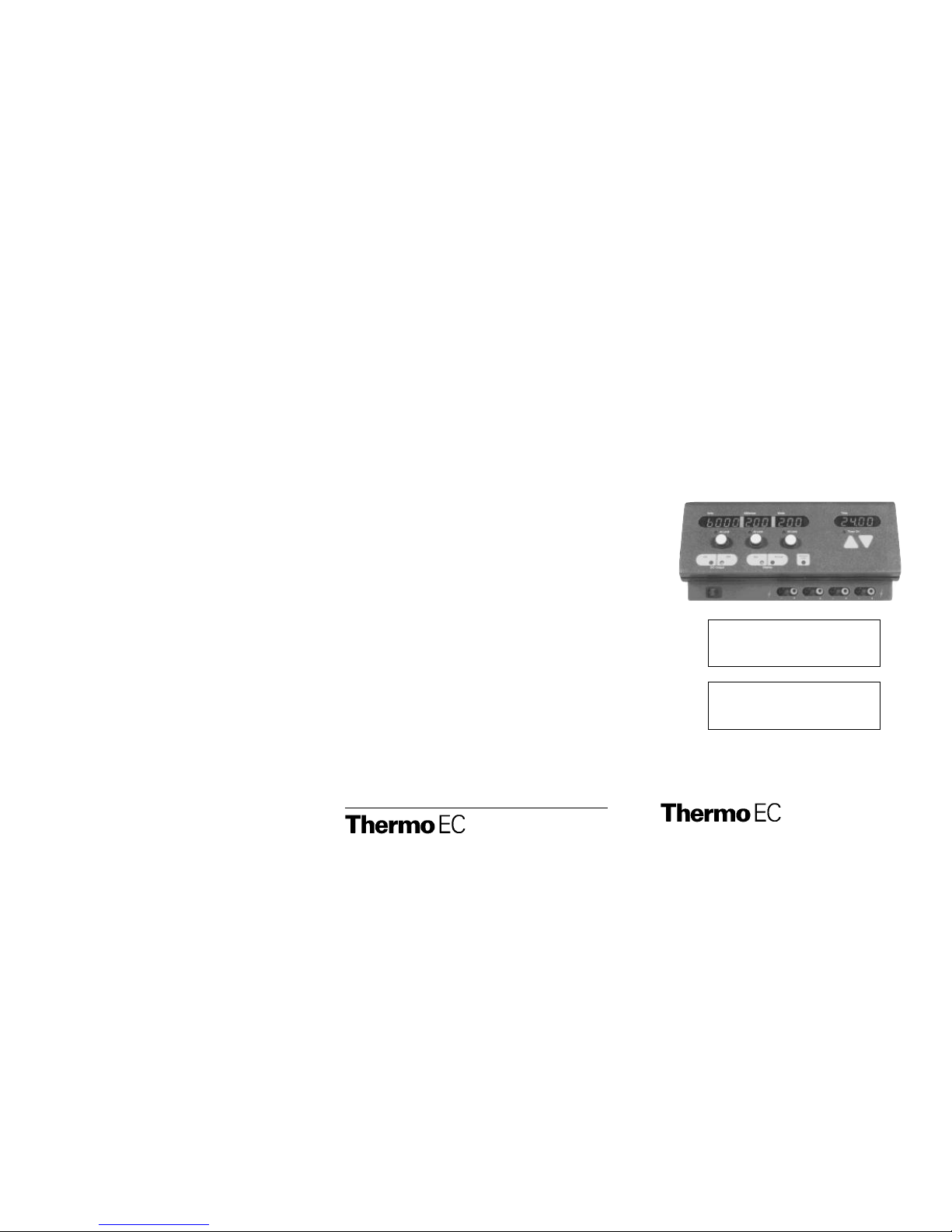
1. Volts adjustment knob
2. Yellow At Limit light (Volts)
3. Volts display
4. Yellow At Limit light (Milliamps)
5. Milliamps display
6. Milliamps adjustment knob
7. Watts display
8. Yellow At Limit light (Watts)
9. Watts adjustment knob
10. Time display
11. Yellow Timer On light
12. Arrow Down key to adjust the timer
13. Arrow Up key to activate and to adjust the timer
14. 4 mm sockets
15. Red Ground Leak light
16. Actual Display key
17. Yellow Actual Display light
18. Yellow Set Display light
19. Set Display key
20. D.C. Output Off key.
21. Green D.C. Output Off light
22. Power On/Off switch
23. Red D.C. Output On light
24. D.C. Output On key
2122
1
24
15
23
3 6 7 854 9 10
11
12
13
14
20 19 18 17 16
2
WARNING
This power supply is designed for use as a source of DC power for electrophore-
sis. It is capable of generating lethal currents. Use the same precautions as with
any electrical device. Do not operate without the cover in place. Do not connect
the output to earth ground. Do not operate in a damp, humid, environment
where condensing moisture may short out internal electrical components. Do not
operate with connecting cables which have exposed live wires. Follow all appro-
priate safety measures outlined by the chamber manufacturer.
AVERTISSEMENT
Ce générateur a été conçu pour être utilisé comme source de courant (DC) pour
l´électrophorèse, et il est capable de générer un courant mortel. Prenez les
mêmes précautions que pour tout autre appareil électrique. N´utilisez pas
l´appareil sans que le couvercle de la chambre soit placé. Ne raccordez pas
les sorties à la terre. N´utilisez pas l´appareil dans des environnements humides,
où la condensation pourrait causer des dommages aux composants électriques
internes. Ne mettez pas l´appareil en route avec des câbles ou partie de câble
dénudé. Ne retirez pas les câbles des sorties de 4 mm pendant que l´appareil
est en fonctionnement. Prendre toutes les précautions recommandé par le fabri-
quant de la chambre d´électrophorèse.
SAFETY NOTICES
NOTICES DE SÉCURITÉ
WARNING: This notice alerts you to a potentially dangerous
situation.
AVERTISSEMENT:
Cette notice attire votre attention sur des dangers
potentiels.
CAUTION: This notice means serious damage may occur to your
power supply or chamber.
ATTENTION: Cette notice attire votre attention sur des dangers
sérieux pour votre générateur ou votre chambre
d´électrophorèse.
NOTE:
This notice gives useful advice or suggestions to raise
the performance or reliability of your power supply.
NOTE:
Cette notice vous donne des conseils vous permettant
d´augmenter la performance et la fiabilité de votre
générateur.
▲
▲
▲
▲
!
▲
!
▲
▲
▲
▲
▲
THERMO EC HIGH VOLTAGE POWER SUPPLIES
THERMO EC HIGH VOLTAGE POWER SUPPLIES
1. The voltage applied to both Cell “A” and Cell “B” is 100 volts. (Rule 1)
2. The sum of the currents flowing through Cell “A” and Cell “B” is equal to
60 milliamps. (Rule 3)
Switch off the power supply and momentarily disconnect Cell “B”. Switch the power
supply back on and note how the output current reading drops to 35 milliamps.
From this, the following information can be derived.
1. The current flow through Cell “B” is equal to 60 milliamps, minus 35 milliamps,
i.e., a net value of 25 milliamps. (Rule 3)
2. The reason Cell “A” and Cell “B” have different current readings is due to the
difference in resistance between Cells “A” and “B”. (Rule 2)
TABLE OF CONTENTS
Intended Uses .............................................. 2
Set-Up ........................................................ 2
Basic Operating Instructions............................ 2
Choosing Safe Operating Limits....................... 5
Setting and Resetting the Timer ........................10
Troubleshooting Guide...................................11
Service .......................................................13
Specifications...............................................14
Appendix A. Relationship Between Volts,
Milliamps, Watts and Chamber Resistance........15
Appendix B. Running Multiple Chambers...........15
Guarantee...................................................16
Locator Guide..............................................fold out back page
1
GUARANTEE
This laboratory equipment was produced by Thermo EC with the highest
practical standards of materials, workmanship, and design. The design
and manufacture of parts have been conceived with one purpose — to
produce a unit which will give satisfactory service.
Thermo EC guarantees this unit to be free from defects in materials or
workmanship under normal use or service for four years from date of
shipment. If, during this time, this unit proves defective in materials or
workmanship, the Company will repair or replace it free of charge if
returned to us prepaid. This guarantee does not cover damage in transit,
damage caused by carelessness, misuse or neglect, or unsatisfactory
performance as a result of conditions beyond our control or consequen-
tial losses as a result of failure of our product.
16
THERMO EC HIGH VOLTAGE POWER SUPPLIES THERMO EC HIGH VOLTAGE POWER SUPPLIES

15
INTENDED USES
This power supply is intended to be used with electrophoretic devices which
operate below the rated output levels listed below. The maximum output levels
are shown for each model using this instruction manual. Four sets of output
connectors operate in parallel to provide an output of constant voltage, constant
current (milliamps) or constant power (watts).
• Model EC600-90 4000 V, 300 mA, 300 W
• Model EC2060 2000 V, 600 mA, 300 W
• Model EC3000-90 3000 V, 300 mA, 300 W
• Model EC6000-90 6000 V, 200 mA, 200 W
SET-UP
Unpacking of the Unit: Unpack and inspect the power supply carefully
for any damage. Do not use the unit if it is damaged. If damage is found,
save the packing material and report the problem to Thermo EC or your local
distributor.
Location: Make sure that the unit is set up in a location where it is pro-
tected from physical damage, moisture, corrosive agents and extreme tem-
peratures, and make sure that the “fins” at the rear are not obstructed. The
unit should be readily accessible for safe operation.
Connection with the AC Mains: Connect the unit to the AC mains
carrying the appropriate specified voltage (V) in accordance with the rating
label located at the rear of the unit. Make sure that the mains receptacle and
the power supply plug both have the proper 3–wire (grounded or earthed)
connections.
BASIC OPERATING INSTRUCTIONS
(See fold out locator guide on last page)
Notes on General Operation: The output of this power supply is con-
trolled by three separate operating limits. An operating limit, with a value
above zero, must be set for voltage, milliamps and watts in order to generate
an output. Once activated, the output of the power supply will then increase
until an operating limit is reached. When this occurs, one of the three yellow
At Limit lights will be illuminated. This light will indicate which operating limit
has been reached and which mode of control (constant volts, current or
power) has been established. The detailed instructions contained in this man-
ual refer to adjustment for operation in constant voltage. In principal, the
method is the same for any mode of operation; only the value of operating
limits change.
For added convenience, this power supply will restart itself in the event of a
power failure. This will not reset the operation of the count–down timer.
2
▲
▲
!
▲
!
▲
APPENDIX A. Relationships Between Volts, Milliamps,
Watts and Chamber Resistance
There are three fundamental concepts which form the basis for understanding the
relationship between volts, milliamps and chamber resistance. When combined with
the power formula they also define watts.
1 A movement of free electrons from atom to atom forms an electric current which
is measured in milliamps (mA) or amps (A).
2. Electrostatic lines of force between two different charges produce a pressure that
can move electrons (measured in volts).
3. All substances oppose the movement of electrons to some extent and are said to
have resistance (measured in ohms).
These three factors are always present in any operating electric circuit. It is possible
to incorporate them into one inclusive statement:
Ohm’s Law
The value of the current that will flow in any circuit will be
directly proportional to the value of the voltage applied and
inversely proportional to the value of the resistance.
or
amps = volts / resistance
combined with
The power formula:
volts x amps = watts
(where 1 amp = 1000mA)
Together, these two formulas define all aspects of the relationship between volts,
milliamps, watts and chamber resistance.
APPENDIX B. Running Multiple Chambers
This power supply is equipped with four sets of 4 mm output connectors which are
connected in parallel. The significance of this is explained by following statements:
1. The voltage is applied equally to all branch paths in a parallel circuit.
2. The current flow in the branch paths of a parallel circuit is determined by the
resistance of the individual paths.
3. The sum of the currents entering the branch paths of a parallel circuit is equal to
the sum of the currents leaving the branch paths of a parallel circuit.
A practical example of this is described as follows:
The power supply is connected to two identical horizontal submarine electrophoresis
chambers (cells A and B). The power supply output is adjusted to 100 volts, at con-
stant voltage, and the current display indicates 60 milliamps. By applying the three
rules for parallel circuits we can determine the following information.
THERMO EC HIGH VOLTAGE POWER SUPPLIES THERMO EC HIGH VOLTAGE POWER SUPPLIES
SPECIFICATIONS
High Voltage Power Supplies (refer to page 2 for models)
Type Output: Constant Voltage, Constant Watts or
Constant Milliamps with automatic crossover
Maximum Voltage: 2000 – 6000 Volts, (depending on model)
Maximum Current: 200 – 600 Milliamps (depending on model)
Maximum Power: 200 – 300 Watts (depending on model)
Regulation: ≤1%
Accuracy: ± 1.5% full scale for each display
Number of
Output Terminals: Four recessed sets of 4 mm sockets
Safety Interlock: Load sensing shut-down-on-disconnect. D.C.Output On
key actuation necessary to begin voltage generation.
In the event of shutdown due to power interruption,
automatic restart is provided.
Timer: 00 to 99 hrs. 59 min.
Ground Leakage: Leakage of 400 microamps or more will interrupt the
generation of high voltage.
Input Power: 115 VAC/60 Hz./400 W
230 VAC/50 Hz./400 W
Ambient Operating
Temperature Range: 0 ° – 30 °C (non-condensing atmosphere)
Dimensions: 11.25
"
(D) x 12.6
"
(W) x 5
"
(H)
28.6 cm x 32 cm x 12.7 cm
Weight: net: 15.4 lbs. 7 kgs.
shipping: 17 lbs. 7.7 kgs.
14
BASIC OPERATING
INSTRUCTIONS
Operation in
Constant Voltage:
1. The electrophoresis chamber
should first be set up, then filled
with buffer and sample, before
plugging the chamber’s leads
into the appropriate positive
and negative 4 mm sockets
(14) on the power supply.
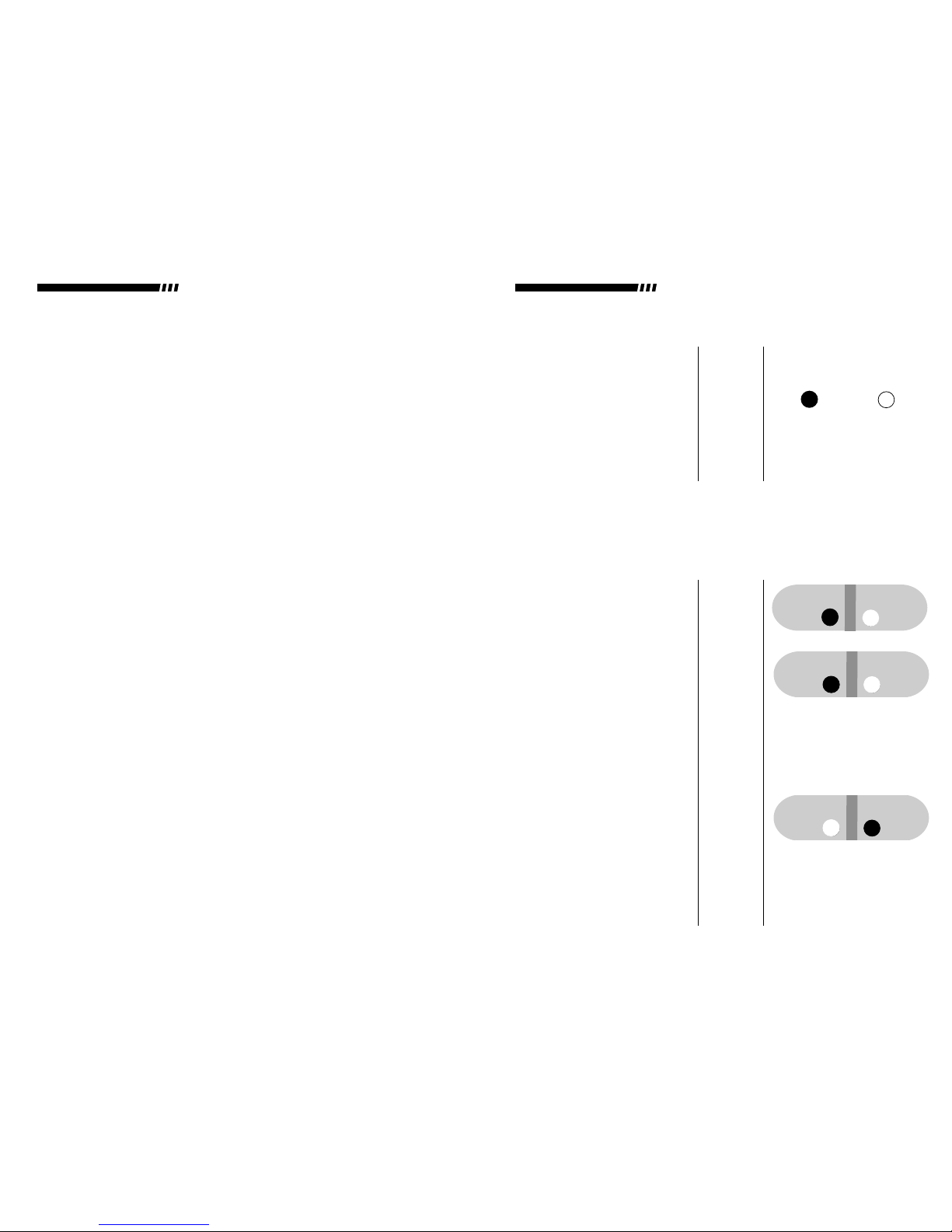
2. Switch on the power supply
using the Power On/Off
switch (22). The main power
switch is marked with a 1 to
indicate on and a 0 to indicate
off. Once on, the Green D.C.
Output Off light (21) and
Yellow Actual Display light (17)
will be illuminated. The Volts
display (3), Milliamps display
(5) and Watts display (7) will
all indicate zero. The Time dis-
play (10) will indicate zero as
well.
3. Gently press the Set Display
key (19). The actual switch itself
is located in the grey area
located immediately below the
word “Set” in the Set Display
key. When pressed, there will
be a tactile sensation, the
power supply will beep and
the Yellow Set Display (18) light
will be illuminated. Each key on
Set Actual
On Off
14
22, 21,
17, 3,
5, 7, 10
19, 18 Set Actual
Locator
Number
Light Off Light On
DC Output
Display
Display
NOTE: An alterntive procedure favored by some users is as follows:
Sample is withheld from the chamber until the power supply has been properly
adjusted and successfully started. Once the user has confirmed that the chamber and
power supply are both functional, the power supply is turned off and sample is
loaded. The power supply will remember its settings, so it can be turned on and start-
ed without further adjustment.
(See fold out locator on last page)
BASIC OPERATING INSTRUCTIONS
3
THERMO EC HIGH VOLTAGE POWER SUPPLIES THERMO EC HIGH VOLTAGE POWER SUPPLIES

13
this power supply has a similar
switch location and sensory cue
upon activation.
4. Using the Volts adjustment knob
(1), select the operating voltage
limit by turning the knob until
the desired value appears on
the Volts display (3).
Rotating the knob slowly in
the clockwise direction will
increase the displayed value
in one–volt increments.
Rotating the knob slowly in the
counterclockwise (anticlock-
wise) direction will reduce the
displayed value in the same
manner. Rotating the same
knob (1) rapidly in either
direction will cause the
displayed value to change in
ten–volt increments.
5. Using the Milliamps Adjustment
knob (6) and Watts Adjustment
knob (9), select the desired
operating limits for milliamps
and watts, respectively. The
method used to select these val-
ues is the same as that used to
select the operating voltage
limit.
CHOOSING SAFE OPERATING
6,9 Milliamps
Watts
WARNING: This power supply is capable of producing output levels well in
excess of the maximum safe operating limits for most electrophoretic chambers. For
this reason, it is important to determine the safe operating limits for milliamps and
watts. The section entitled “Choosing Safe Operating limits” has been included to
guide the user in selecting proper operating limits. This section details both the
method and rationale used in selecting these operating limits.
Volts
1, 3
NOTE: Each adjustment knob has a RAPID ADJUSTMENT MODE which is
activated whenever the knob is rotated rapidly.
4
WARNING
This power supply is not equipped with
any user serviceable parts.
Erratic Operation: Unstable, erratic displays, inoperable timer and/or
adjustment knobs are all possible symptoms of corrupted memory. To clear
this condition turn off the power supply, depress and hold any key and turn
the power supply back on before releasing the key.
Ground Leakage: Ground leakage is the interconnection of earth ground
and either high voltage output. This interconnection will defeat the primary
operator safety feature of this power supply. Do not operate the power supply
when this condition exists. For further assistance, call the telephone number
listed in the service section or contact your local distributor.
SERVICE
Contact Thermo EC for technical assistance if problems occur. The telephone
numbers are 631-244-2929, 1-800-EC-RANGE (toll free U.S.).
▲
▲
▲
▲
NOTE:
If this power supply experiences an electrostatic discharge
of ≥8000 volts an overcurrent message will be displayed and DC
output will shut down.
THERMO EC HIGH VOLTAGE POWER SUPPLIES THERMO EC HIGH VOLTAGE POWER SUPPLIES

C. Ground Leakage Detected: A continuous tone accompanied by the
illumination of the ground leakage light. The voltage and wattage displays
will hold their last value. The milliamps display will go blank. (See below
“Ground Leakage”)
D. Power On Restart: Nine short bursts in groups of three each with
each output display showing decimal points. This alarm activates to alert
the operator to the fact that auto-restart will occur at the end of a mains
power failure. The alarm will clear itself.
E. Overheating Detected: A continuous tone accompanied by flashing
displays. This alarm indicates the heatsink, located at the rear of the unit,
has exceeded safe operating temperatures. Momentarily turning off the
power supply will clear the alarm. (See Service)
F. Mains Overload: A continuous tone accompanied by flashing displays.
This alarm is indistinguishable from the “Overheating detected” alarm. It
indicates an internal fault or a temporary surge in the mains supply.
Momentarily turning off the power supply will clear the alarm. (See Service)
Unit Will Not Start: This power supply is equipped with a load sensing
interlock which is designed to inhibit the generation of high voltage whenever
an open connection is detected at the output.
Open Connection: An open connection is defined as a break in the path
in which electricity normally flows. This could be caused by any of the follow-
ing conditions:
1. A broken electrode within the electrophoretic chamber.
2. A broken wire within the connecting cord (either positive or negative).
3. Insufficient buffer levels within the electrophoretic chamber.
4. Loose connectors in any electrical connection going to or coming from the
power supply or chamber.
5. Electrochemical energy stored within the chamber. (See below, “Unit Will
Not Restart”)
Unit Will Not Restart: Certain types of electrophoretic techniques will,
over a period of time, store energy within the electrophoretic chamber. This
charge may inhibit the normal function of the load sensing interlock when
attempting to restart an experiment which has been temporarily interrupted.
To overcome this effect depress and hold the D.C.Output On key until the
power supply reaches its proper operating voltage. Upon releasing the D.C.
On key the power supply should remain engaged. If it will not remain
engaged refer to the section entitled “Unit Will Not Start”.
No Displays Light: This power supply is equipped with 2 circuit breakers
located at the rear of the instrument. If either circuit breaker is activated the
power supply will not turn on. When activated, the circuit breakers expose a
white stem.
12
6. Gently press the D.C. Output
On key (24). The Red D.C.
Output On light (23) should illu-
minate and the D.C. output as
indicated by the three displays
(3, 5, 7) should rapidly
increase until the operating volt-
age limit is reached. At this
point the Yellow At Limit light
(volts) (2) should be the only “at
limit” light illuminated.
On Off
DC Output
LIMITS
Electrophoretic chambers are generally designed for a relatively specific purpose.
For example, horizontal chambers use agarose gels to separate DNA or RNA frag-
ments while a DNA Sequencing chamber is almost always used to separate DNA
in a denaturing polyacrylamide gel. In each case, the voltage, milliamp and
wattage requirements are well–defined within a reasonable range of values. In
cases such as these, the user can safely assume that the manufacturer has designed
the chamber to withstand the voltage and heat energy necessary to perform the
electrophoretic separation when standard protocols are followed.
Some types of electrophoretic chambers are specifically designed to be multipur-
pose devices. For example, a vertical slab gel chamber could be used for anything
from DNA Sequencing to Isoelectric Focusing depending on the gel type and buffer
system used. Choosing safe operating limits for a chamber of this type requires a
24, 23,
3, 5,
7, 2
5
NOTE: The power supply output may be adjusted while operating. If you turn any
of the three adjustment knobs while the D.C. Output On light is illuminated, the
power supply will automatically switch to the Set Display Mode. Each display will
show the set operating limit while in this mode and new limits may be set. One sec-
ond after releasing the adjustment knob the power supply will revert to the Display
Actual Mode.
Operation in Constant Current: The method used to set the power supply
in constant current is the same as the method used for constant voltage. The only
difference involves the selection of an operating limit for current which, as the out-
put increases, is attained before the operating limits for voltage or watts.
Operation in Constant Watts: The method used to set the power supply in
constant watts is the same as the method used for constant voltage. The only dif-
ference involves the selection of an operating limit for watts which, as the output
increases, is attained before the operating limits for voltage or current.
THERMO EC HIGH VOLTAGE POWER SUPPLIES THERMO EC HIGH VOLTAGE POWER SUPPLIES

Alarm Tones and Displays:
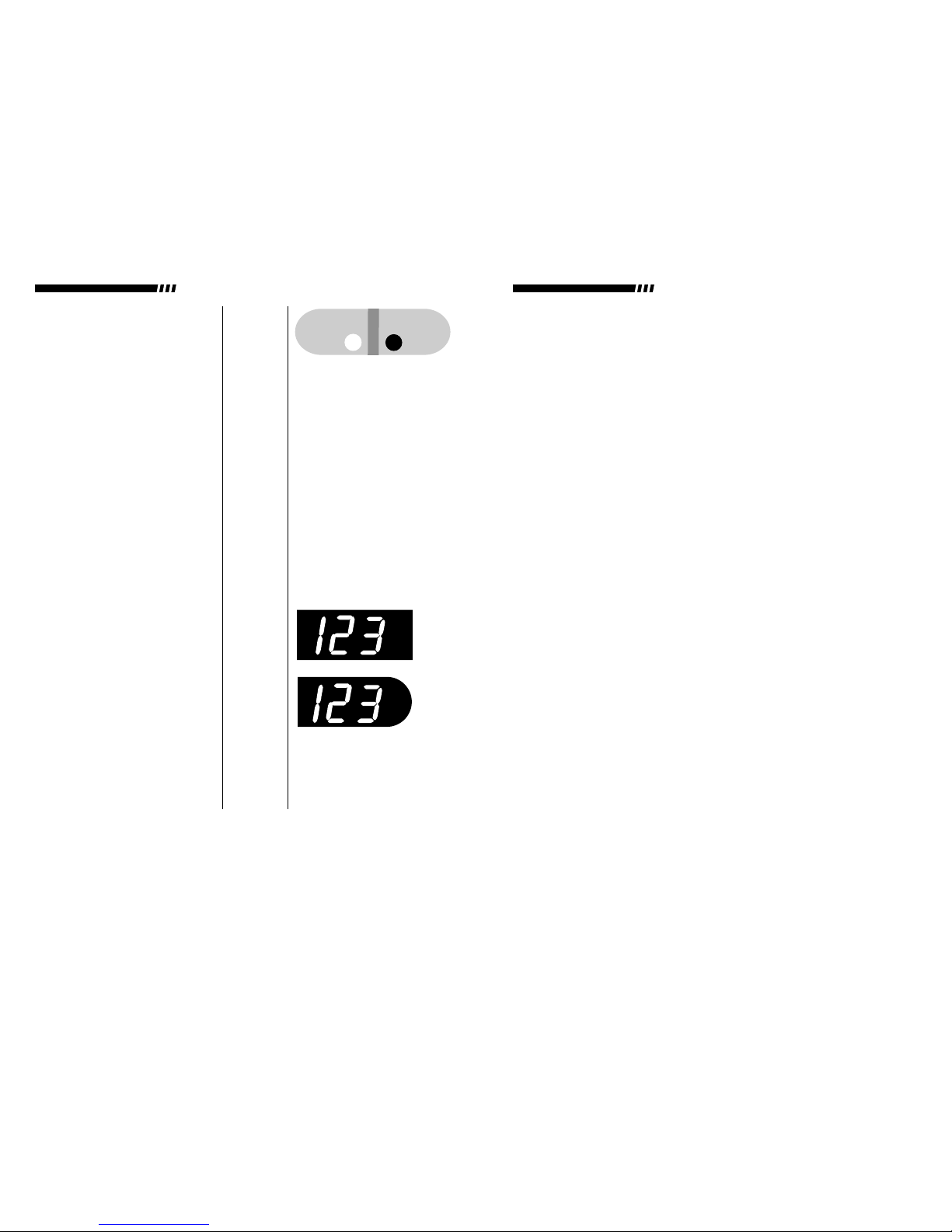
A.Tone Pattern:
Display Pattern:
B. Tone Pattern:
Display Pattern:
C. Tone Pattern:
Display Pattern:
Ground Leakage:
D. Tone Pattern:
Display Pattern:
E. Tone Pattern:
Display Pattern:
F. Tone Pattern:
Display Pattern:
n o L o AD
oo o
GOES BLANK LAST VALUE
. . . . . .
FLASHINGFLASHING FLASHING
FLASHING FLASHING
LAST VALUE
. . . .
FLASHING
Ground
Leak
TROUBLESHOOTING GUIDE
Unit Alarms: This power supply is equipped with both audible and visual
alarms. Items A through F listed immediately below are graphical representa-
tions of each alarm mode. To understand which alarm has been activated and
why, match the letter (A-F) to the corresponding text below.
A. Open Connection: A continuous tone which is generated as soon as
the D.C. Output On key is depressed. The displays will spell noLoAD.
Depressing D.C. Output Off key will cancel the alarm mode. (For cause
see, “Unit will not start”.)
B. Timer At Zero: Nine short bursts in groups of three followed by the
D.C. Off light illuminating. The three output displays will indicate zero.
This indicates that the set time interval has expired.
11
higher degree of caution. Chamber manufacturers normally rate their product for
maximum voltage and/or maximum wattage. Whenever possible, contact the
manufacturer and request this information. It is the safest method of determining if a
chamber is suitable for a particular procedure.
Whether you use special purpose or multipurpose chambers, the maximum operat-
ing temperature the chambers will withstand is a critical aspect of safe operation.
Most electrophoretic chambers (with a few notable exceptions) are made of acrylic
plastic and must operate well below a temperature of 55 °C. If there is a lack of
information about the capabilities of the chamber being used, regular monitoring of
the operating temperature is recommended. This should be done without coming
into physical contact with the chamber when voltage is applied. Use the procedure
listed below to select operating parameters.
PROCEDURE:
(See fold out on last page)
1. The electrophoresis chamber
should first be set up, then
filled with buffer and sample,
before plugging the cham-
ber’s leads into the appropri-
ate positive and negative
4 mm sockets (14) on the
power supply.
2. Switch on the power supply
using the Power On/Off
switch (22). Once on, the
Green D.C. Output Off light
(21) and Yellow Actual
Display light (17) will be illumi-
nated. The Volts display (3),
Milliamps display (5) and
Watts display (7) will all indi-
cate zero. The Time display
(10) will indicate zero as well.
On Off
14
22, 21,
17, 3,
5, 7, 10 DC Output
NOTE: An alternative procedure favored by some users is as follows:
Sample is withheld from the chamber until the power supply has been properly
adjusted and successfully started. Once the user has confirmed that the chamber and
power supply are both functional the power supply is turned off and sample is
loaded. The power supply will remember its settings, so it can be turned on and start-
ed without further adjustment.
Set Actual
Display
6
THERMO EC HIGH VOLTAGE POWER SUPPLIES THERMO EC HIGH VOLTAGE POWER SUPPLIES
SETTING AND RESETTING THE TIMER (See fold out locator on last page)
Notes on Timer Operation: This power supply is equipped with a multi-
function timer. In the passive mode the timer accrues elapsed time whenever the
D.C. On light is illuminated. The elapsed time resets to zero whenever the D.C. Off
light is illuminated or the mains power is switched off. To function as a count–down
timer, a time interval must be set using the up/down arrow keys. Each arrow key
adjusts the timer in a single direction. For convenience, the time increments switch
from minutes to hours after continuously depressing either key for several seconds.
Once set, the timer will count down whenever the D.C. On light is illuminated. The
Timer On light will illuminate whenever the count–down mode is activated. Upon
reaching zero time remaining, the power supply will sound an alarm and switch off
the output. After timer goes to zero it will reset itself to the original time. To disable
the count–down mode of operation the time interval must be reset to zero.
Setting:
1. Switch on the power supply using the Power On/Off switch (22). Once on, the
Green D.C. Output Off light (21) and the Yellow Actual Display light (17) will be
illuminated. The Volts display (3), Milliamps display (5), and Watts display (7) will
all indicate zero.
2. Gently depress the center of the Arrow Up key (13). When pressed there will be
a tactile sensation and the time shown on the Time display (10) will begin to
increase. Continue depressing the Arrow Up key until the Time display indicates
the desired time interval.
Note: For convenience, the incremental changes in time switch to hours after
continuously depressing either Arrow key for several seconds.
3. Confirm that all operating limits are correct, the power supply is properly connect-
ed to the electrophoretic chamber and gently depress the D.C. Output On key
(24). Once on, the Red D.C. Output On light (23) and the Yellow Timer On light
(11) will be illuminated and the timer will begin counting down.
Resetting:
1. Switch on the power supply using the Power On/Off switch (22). Once on, the
Green D.C. Output Off light (21) and the Yellow Actual Display light (17) will be
illuminated. The Volts display (3), Milliamps display (5), and Watts display (7) will
all indicate zero.
2. Gently depress the center of the Arrow Down key (12). When pressed there will
be a tactile sensation and the time shown on the Time display (10) will begin to
decrease. Continue depressing the Arrow Down key until the Time display indi-
cates zero time remaining.
3. Confirm that all operating limits are correct, the power supply is properly connect-
ed to the electrophoretic chamber and gently depress the D.C. Output On key
(24). Once on, the Red D.C. Output On light (23) will be illuminated and the
timer will begin accruing elapsed time.
10
Watts
3. Gently press the Set Display
key (19). The actual switch
itself is located in the gray
area located immediately
below the word “Set” in the
Set Display key. When
pressed there will be a tactile
sensation, the power supply
will beep and the Yellow Set
Display (18) light will be illumi-
nated. Each key on this
power supply has a similar
switch location and sensory
cue upon activation.
4. Using the Volts adjustment
knob (1), select the operating
voltage limit by turning the
knob until the desired value
appears on the Volts display
(3). Rotating the knob slowly
in the clockwise direction will
increase the displayed value
in one–volt increments. Rotat-
ing the knob slowly in the coun-
terclockwise (anticlockwise)
direction will reduce the dis-
played value in the same man-
ner. Rotating the same knob (1)
rapidly in either direction will
cause the displayed value to
change in ten–volt increments.
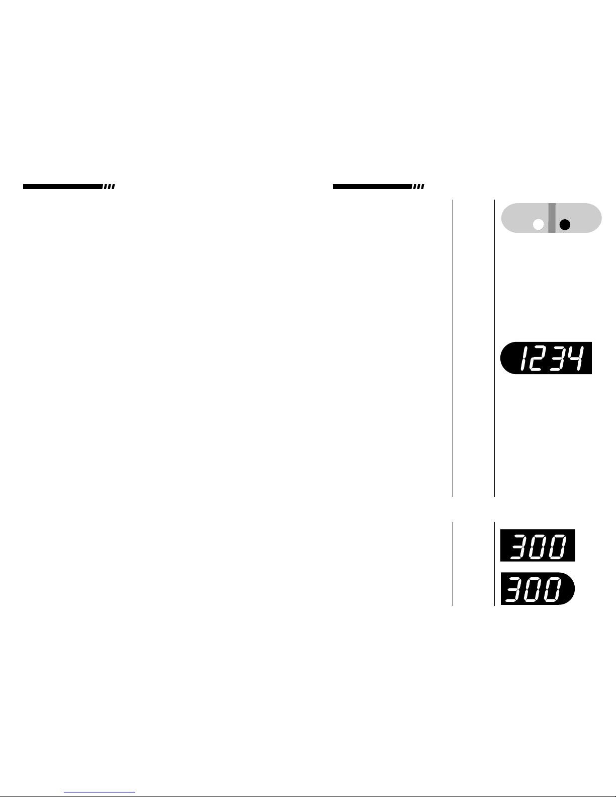
5. Using the Milliamps and Watts
adjustment knobs (6, 9), select
the maximum operating limits of
300 milliamps and 300 watts
respectively.
19, 18
1, 3
6, 9
Volts
NOTE: Each adjustment knob has a RAPID ADJUSTMENT MODE which is
activated whenever the knob is rotated rapidly.
7
▲
!
Set Actual
Display
Milliamps
THERMO EC HIGH VOLTAGE POWER SUPPLIES THERMO EC HIGH VOLTAGE POWER SUPPLIES
NOTE: Utilizing Automatic Crossover
Certain electrophoretic techniques require the careful adjustment of operating limits
to utilize a function of this power supply known as automatic crossover. Automatic
crossover is a method used when the experiment requires two or more modes of
operation during the course of the experiment.
The most common example of a technique which requires this function is semi-dry
electrophoretic transfers of proteins or nucleic acids. Semi-dry transfer chambers
consist of two closely spaced parallel plates which serve as electrodes. Positioned
between these plates is a sandwich consisting of buffer–saturated filter paper
sheets on the outside and the gel and charged membrane on the inside. Typically,
the transfer process is most efficiently accomplished by applying a constant current
flow between the two plates. As the transfer progresses, the buffer in the filter
paper begins to break down. This leads to an increase in overall resistance
between the two plates.Since the power supply is trying to maintain constant cur-
rent, it increases the voltage output to compensate for the increased resistance. Left
unchecked, the increasing voltage would eventually reach a potential great
enough to arc over between the plates, resulting in damage to the chamber and
experiment failure.
Automatic crossover can be used to prevent this unfortunate incident from
occurring. Set an operating limit for voltage at a value below the arc–over
threshold (for example, a limit that is 10% above the starting voltage). As the
voltage increases during the experment, it will eventually reach the operating
limit for voltage and “automatically crossover” to constant voltage operation.
At this point, the current will start to drop as the buffer breaks down, but the
experment and chamber will be unharmed.
9
6. Gently press the D.C. Output On
key (24). The Red D.C. Output
On light (23) should illuminate
and the D.C. output as indicated
by the three displays (3, 5, 7)
should rapidly increase until the
operating voltage limit is
reached. At this point the Yellow
At Limit light (volts) (2) should be
the only “at limit” light illuminat-
ed.
7. Once the power supply has
reached the operating voltage
limit, note the actual values
displayed for milliamps and
watts.
8. Add 10 watts and 15 milliamps
to the actual values noted
above.
9. Rotate the Milliamps Adjustment
Knob (6). The power supply will
automatically switch to the
Display Set Mode and the
Yellow Set Display light (18) will
be illuminated. Adjust the
Milliamps Adjustment Knob
downward until the new limit
value has been achieved.
Repeat this process with the
Watts Adjustment Knob (9) .
Once set to the new operating
limits, the power supply will auto-
matically return to the Actual
Display Mode and the Yellow
Actual Display light (17) will be
illuminated.
6, 18,
9, 17
24, 23,
3, 5,
7, 2
On Off
DC Output
Milliamps
Watts
8
NOTE: It may be necessary to readjust the watt or milliamp operating limit during
the course of the separation process to ensure that the entire procedure is performed
at a constant voltage. This readjustment, if necessary, is required to compensate for
large changes in resistance which occur during certain types of electrophoresis.
THERMO EC HIGH VOLTAGE POWER SUPPLIES THERMO EC HIGH VOLTAGE POWER SUPPLIES
This manual suits for next models
3
Table of contents


