Njoy Garun Series User manual

Garun Series
User Manual
10KL / 15KL / 20KL 3:3 / 3:1 / 1:1 UPS
UP33TOP110KGAAZ01B
UP33TOP115KGAAZ01B
UP33TOP120KGAAZ01B
UP33TOP110KGAAZ02B
UP33TOP120KGAAZ02B
938.35.21.0Before using this product, carefully read all product documentaon and retain it for future reference.

2 3
This User Manual is compable with the following Garun Series models:
10K VA
15K VA
20K VA
Garun 10KL
Garun 15KL
Garun 20KL
Thank you for purchasing our products!
Please read this manual before using the product.
nJoy
Table of contents
1. Safety and EMC instrucons .................................................................................. 5
1-1. Transportaon and storage ...................................................................................... 5
1-2. Preparaon .................................................................................................................. 5
1-3. Installaon .................................................................................................................. 5
1-4. Connecon warnings ................................................................................................ 6
1-5. Operaon ..................................................................................................................... 7
1-6. Standards .................................................................................................................... 7
2. Installaon and operaon ....................................................................................... 8
2-1. Unpacking and inspecon ...................................................................................... 8
2-2. Wiring terminal view ............................................................................................... 9
2-3. UPS Posioning...........................................................................................................11
2-4. Single UPS installaon .......................................................................................... 12
2-5. UPS installaon for parallel system ..................................................................... 17
2-6. Soware installaon ............................................................................................. 17
3. Operaons .............................................................................................................. 18
3-1. Inial operaon ........................................................................................................ 18
3-2. Screen descripon ................................................................................................... 19
3-2.1. Main screen .................................................................................................... 19
3-2.2. Control screen ................................................................................................. 20
3-2.3. Measure screen ............................................................................................. 22
3-2.4. Seng screen ............................................................................................... 24
3-2.5. Informaon screen ....................................................................................... 32
3-2.6. Data Log screen ............................................................................................... 35
3-3. Audible alarm............................................................................................................ 36
3-4. Single UPS operaon .............................................................................................. 36
3-5. Parallel operaon ................................................................................................... 40
3-6. Fault code ................................................................................................................. 43
3-7. Warning code ........................................................................................................... 45
4. Troubleshoong .................................................................................................. 46
5. Storage and maintenance ...................................................................................... 48
5-1. Storage ......................................................................................................................... 48
5-2. Maintenance ............................................................................................................... 48

4 5
Safety and EMC instructions1
All safety instrucons in this document must be read, understood and
followed.
1.1. Transportaon and storage
• Please transport the UPS system only in the original packaging to protect
against shock and damage.
• The UPS must be stored in the room where the temperature is well
regulated. Ambient temperature should not exceed 40°C.
1.2. Preparaon
• Condensaon may form if the UPS system is moved from cold to warm
environment immediately.
• The UPS system must be absolutely dry before being installed.
Please allow at least two hours for the UPS system to acclimate with the
environment.
• Do not install the UPS system near water or in moist environments.
• Do not install the UPS system where it would be exposed to direct
sunlight or near by heat source.
• Do not block venlaon holes on the UPS housing.
1.3. Installaon
• Do not connect appliances or devices which would overload the UPS (e.g.
big motor type equipment) to the UPS output terminal.
• Place cables in such a way that no one can step on or trip over them.
• Do not block air vents on the housing of the UPS. Ensure proper unit
spacing of venlaon.
• UPS equipped with grounding terminal, in the nal installaon phase,
connect grounding/earthing wire to the external UPS baery cabinets or
appropriate grounding terminals
• The UPS can be installed only by qualied maintenance personnel.
• An appropriate disconnect device such as short circuit backup protecon
should be incorporated during installaon.
• An integral emergency shuto switch which prevents addional load
from the UPS in any mode of operaon should be implemented during the
installaon.
• Secure the grounding/earthing wire before connecng to any live wire
terminal.
• Installaon and Wiring must be in accordance with the local electrical
laws and regulaons.
We assume no responsibility or liability for loss or damages, whether direct,
indirect, consequenal or incidental, which might arise out of the use of such
informaon. The use of any such informaon will be enrely at the user’s risk.
Informaon in this manual is subject to change without noce. We make no
commitment to update or keep current the informaon in this manual. If you
nd informaon in this manual that is incorrect, misleading, or incomplete, we
would appreciate your comments and suggesons.
Please comply with all warnings and operang instrucons in this manual.
This equipment should only be installed, serviced, and maintained by
qualied personnel. If you are the beneciary of this UPS and you encounter
any problem with it, please contact authorized personel who installed the
UPS. Do not operate this unit before reading through all safety informaon
and operang instrucons carefully.
DANGER!
This UPS carries lethal voltages. Installaon, maintenance, service and repairs
must be performed by authorized personnel only. There are no user-serviceable
parts inside the UPS. Do not aempt to modify any sengs of the UPS unless
you are a trained technician. If you need to change any sengs of this UPS or
you have technical warnings or faults shown on UPS screen, please contact the
technician that installed the UPS.
WARNING
6 7
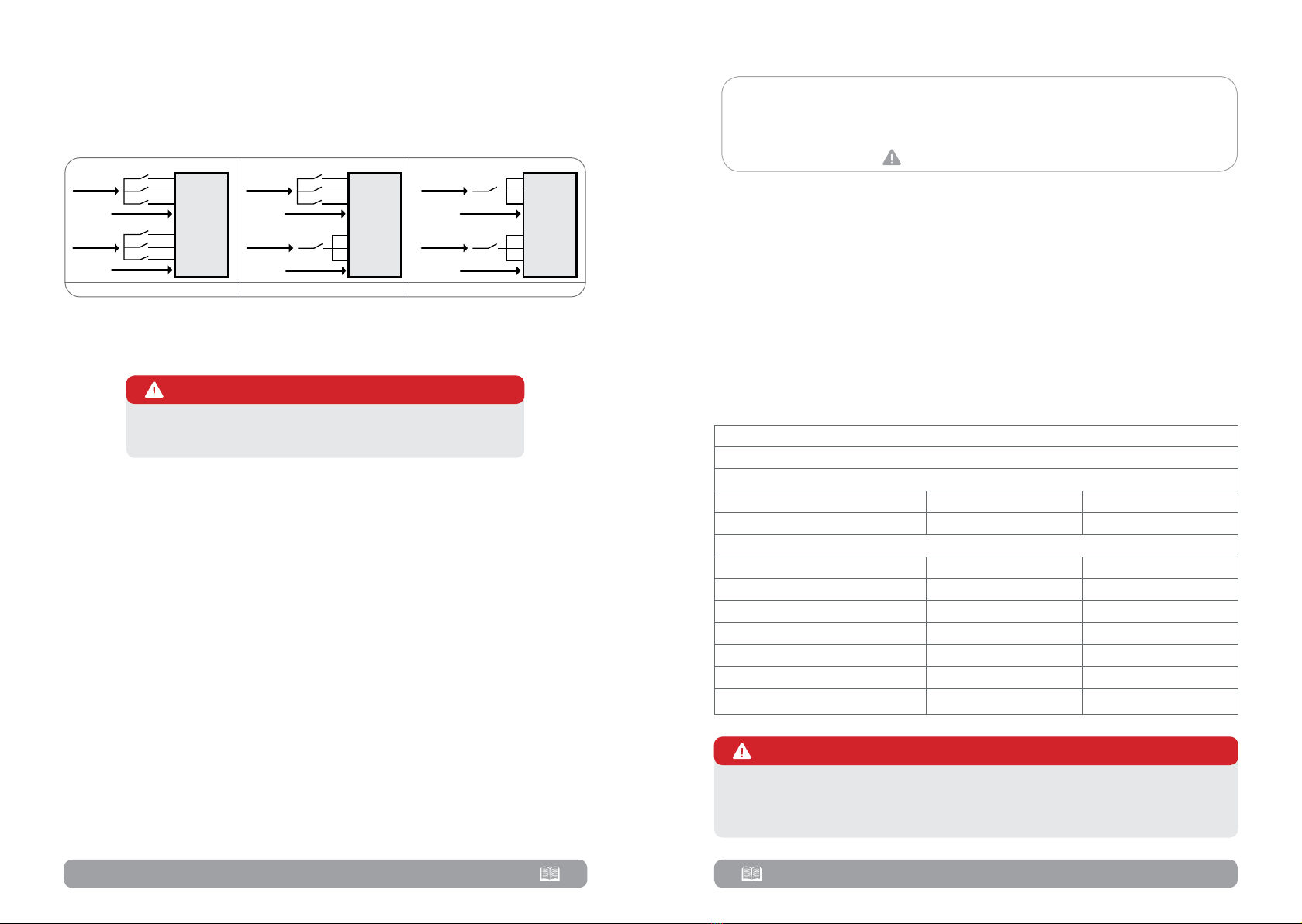
1.4. Connecon warnings
• There is no standard backfeed protection inside of the UPS. However,
there are relays on the Input to cut off line voltage while the neutral is still
connect to UPS.
UPS
Main
Input
Input Rly
Input Rly
N
L1
L2
L3
Bypass
Input
N
L1
L2
L3
UPS
Main
Input
Input Rly
Input Rly
L1
L2
L3
N
Bypass
Input
Input Rly
L1
N
UPS
Main
Input
Input Rly
L1
Bypass
Input
N
Input Rly
L1
N
3:3 phase 3:1 phase 1:1 phase
• This UPS should be connected with TN grounding/earthing system.
• The power input for this unit must be 3:3/3:1/1:1 rated in accordance
with the equipment configuration. It also must be suitably grounded.
High leakage current!
Earth connecon essenal before connecng supply!
WARNING
• Use of this equipment in medical instrument of any life-sustaining
equipment where failure of this equipment can reasonably be expected to
cause the failure of the life-sustaining equipment or to significantly affect its
safety or effectiveness is not recommended. Do not use this equipment in
the presence of a flammable mixture with air, oxygen or nitrous oxide.
• Connect grounding terminal of UPS to a grounding electrode conductor.
• In accordance with safety standard EN-IEC 62040-1, installation has to
be provided with a system, as for example a contactor,
which will prevent the appearance of voltage or dangerous energy in the input
mains during a mains fault (respect the wiring diagram of
depending if the equipment is with signal or three phase input).
NOTE!
• Warning labels should be placed on all primary power switches installed
in places away from the unit to alert the electrical maintenance personnel of
the presence of a UPS in the circuit. The label will bear the following or an
equivalent text:
Before working on this circuit
1. Isolate Uninterruptible Power Supply (UPS)
2. Then check for Hazardous Voltage between all terminals including the
protected earth.
Risk of Voltage Backfeed
1.5. Operaon
• Do not disconnect the grounding/earthing conductor cable on the UPS or
the building wiring terminals under any circumstance.
• The UPS system features its own, internal current source (batteries). The
UPS output sockets or output terminal blocks may be electrically live even if
the UPS system is not connected to the building mains/live wires .
• In order to fully disconnect the UPS system, first press the “OFF” button
and then disconnect the mains/live wires .
• Ensure that no liquid or other foreign objects can enter into the UPS
system.
1.6. Standards
*Safety
IEC/EN 62040-1
*EMI
Conducted Emission IEC/EN 62040-2 Category C3
Radiated Emission IEC/EN 62040-2 Category C3
*EMS
ESD IEC/EN 61000-4-2 Level 4
RS IEC/EN 61000-4-3 Level 3
EFT IEC/EN 61000-4-4 Level 4
SURGE IEC/EN 61000-4-5 Level 4
CS IEC/EN 61000-4-6 Level 3
Power-frequency Magnec eld IEC/EN 61000-4-8 Level 4
Low Frequency Signals IEC/EN 61000-2-2
This is a product for commercial and industrial applicaon and the
second environment installaon restricons or addional measures may
be needed to prevent disturbances.
WARNING

8 9
2.1. Unpacking and inspecon
Unpack the package and check the package contents. The shipping package
should contain:
• One UPS
• One USB cable
• For Garun 10 KL (UP33TOP110KGAAZ01B and
UP33TOP110KGAAZ02B) you should have the following cables:
No. Descripon Length
(cm)
Quanty
(pcs) Observaons
110 AWG cable (Black) 10 16 F2 to F2 connector
210 AWG cable (Black) 30 2 F2 to F2 connector
3UPS to Cabinet 3x AWG 8
(Red/Blue/Black) 150 1 11.5mm (ANEN) to
11.5mm (ANEN)
• For Garun 15 KL (UP33TOP115KGAAZ01B) and Garun 20 KL
(UP33TOP120KGAAZ01B and UP33TOP120KGAAZ02B) you should
have the following cables:
No. Descripon Length
(cm)
Quanty
(pcs) Observaons
110 AWG cable (Black) 10 29 F2 to F2 connector
210 AWG cable (Black) 30 8 F2 to F2 connector
310 AWG cable (Black) 65 1F2 to F2 connector
4UPS to Cabinet 3x AWG 6
(Red/Blue/Black) 150 1 11.5mm (ANEN) to
11.5mm (ANEN)
NOTE!
Installation and operation2 2.2. Wiring terminal view
1RS-232 communication port
2USB communication port
3 Emergency power off function connector (EPO connector)
4Share current port
5Parallel port
6Intelligent slot
7 External battery connector/terminal
8 Line input circuit breaker/switch
9 Maintenance bypass switch
10 Input/Output terminal (
11 Bypass input circuit breaker/switch
12 Output switch

10 11
Diagram 1: Garun 10KL/15KL/20KL
Rear panel
2.3. UPS Posioning
The UPS should be installed in the environment with free ventilation, less
dust, optimum ambient temperature and humidity.
The recommended ambient temperature is 20°C~25°C with 50% humidity.
• Ambient temperature: 0°C~+40°C
• Storage temperature: -15ºC ~ 60ºC
• Relative humidity: 0 ~ 95%
• Altitude: If the UPS is installed within 1000m, the UPS power will not be
derated. When the altitude is over 1000m, the output power will be derated
by following the table.
Altude(m) 1000 1500 2000 2500 3000 3500 4000 4500 5000
Coecient 100% 95% 91% 86% 82% 78% 74% 70% 67%
• Vertical: No vibration and the degree of deviation from vertical shouldn’t
be more than 5°.
• Space: It’s requested to have a clearance of approx. 50 cm to the front
and back of the unit and approx. 50 cm to the side.
Cauon!

12 13
2.4. Single UPS installaon
Installation and wiring must be carried out in accordance with the local
electric laws and regulations by trained professionals.
Step 1. Make sure that the mains wire and breakers of the building are
rated for the capacity of the UPS to prevent electric shock or risk of fire.
NOTE!
Step 2. Switch off the mains switch in the building before installation.
Step 3. Turn off all the connected devices before connecting to the UPS.
Step 4. Prepare wires based on the following table:
Model Wiring spec (minimum A cable should support)
Phase mode Input (Ph) Output (Ph) Neutral Baery Ground
Garun 10KL
(UP33TOP110KGAAZ02B) 3:3 16A 16A 28A 32A 16A
Garun 10KL
(UP33TOP110KGAAZ02B)
3:3 16A 16A 28A 32A 16A
3:1 16A 46A 28A 32A 16A
1:1 48A 46A 85A 32A 48A
Garun 15KL
(UP33TOP115KGAAZ01B) 3:3 24A 24A 42A 48A 24A
Garun 20KL
(UP33TOP120KGAAZ01B) 3:3 32A 32A 55A 62A 32A
Garun 20KL
(UP33TOP120KGAAZ02B)
3:3 32A 32A 55A 62A 32A
3:1 32A 92A 55A 62A 32A
1:1 96A 92A 165A 62A 96A
Step 5. Remove the terminal block cover at the rear panel of UPS. Then
connect the wires according to the following terminal block diagrams:
Cable connecon for 3:3 models
For 3:3 models (Garun 10KL with PN: UP33TOP110KGAAZ01B, Garun
15KL with PN: UP33TOP115KGAAZ01B and Garun 20 KL with PN:
UP33TOP120KGAAZ01B) cables should be connected according to below
diagram:
Diagram 2: Terminal block wiring diagram for Garun 10KL/15KL/20KL
• The cables for Garun 10KL (PN UP33TOP110KGAAZ01B) should be able
to withstand over 16A current for Input and Output phase, 28A for Neutral,
32A for batteries and 16A for Ground. Please use corresponding thickness
for each wire.
• The cables for Garun 15KL (PN UP33TOP115KGAAZ01B) should be able
to withstand over 24A current for Input and Output phase, 42A for Neutral,
48A for batteries and 24A for Ground. Please use corresponding thickness
for each wire.
• The cables for Garun 20KL (PN UP33TOP120KGAAZ01B) should be able
to withstand over 32A current for Input and Output phase, 55A for Neutral,
62A for batteries and 32A for Ground. Please use corresponding thickness
for each wire.
Cable connecon for 3:3/3:1/1:1 models
For 3:3 / 3:1 / 1:1 models (Garun 10KL with PN UP33TOP110KGAAZ02B
and Garun 20 KL with PN UP33TOP120KGAAZ02B) the cables should be
connected based on phase configuration of the UPS. Below you have details
for each of the possible configurations.
NOTE!

14 15
3:3 phase configuration
Please use the below diagram: (3.a)
• For 3:3 configuration, the cables for Garun 10KL (PN
UP33TOP110KGAAZ02B) should be able to withstand over 16A current
for Input and Output phase, 28A for Neutral, 32A for batteries and 16A for
Ground. Please use corresponding thickness for each wire.
• For 3:3 configuration, the cables for Garun 20KL (PN
UP33TOP120KGAAZ02B) should be able to withstand over 32A current
for Input and Output phase, 55A for Neutral, 62A for batteries and 32A for
Ground. Please use corresponding thickness for each wire.
3:1 phase configuration
Please use the below diagram: (3.b)
NOTE!
• For 3:1 configuration, the cables for Garun 10KL (PN
UP33TOP110KGAAZ02B) should be able to withstand over 16A current for
Input phase, over 46A for Output phase, 28A for Neutral, 32A for batteries
and 16A for Ground. Please use corresponding thickness for each wire.
• For 3:1 configuration, the cables for Garun 20KL (PN
UP33TOP120KGAAZ02B) should be able to withstand over 32A current for
Input phase, over 92A for Output phase, 55A for Neutral, 62A for batteries
and 32A for Ground. Please use corresponding thickness for each wire.
1:1 phase configuration
Please use the below diagram: (3.c)
NOTE!
• For 1:1 configuration, the cables for Garun 10KL (PN
UP33TOP110KGAAZ02B) should be able to withstand over 48A current for
Input phase, over 46A for Output phase, 85A for Neutral, 32A for batteries
and 48A for Ground. Please use corresponding thickness for each wire.
• For 1:1 configuration, the cables for Garun 20KL (PN
UP33TOP120KGAAZ02B) should be able to withstand over 96A current for
Input phase, over 92A for Output phase, 165A for Neutral, 62A for batteries
and 96A for Ground. Please use corresponding thickness for each wire.
16 17
NOTE!
Please install the output breaker between the output terminal and the load,
and the breaker should be qualified with leakage current protective function
if necessary.
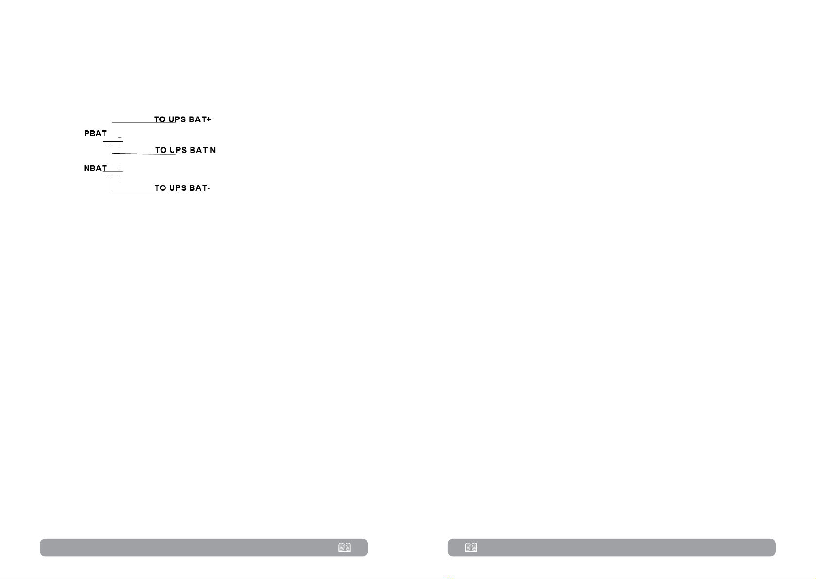
Baery wire connect schemac in addional baery cabinet
Battery wire connect
schematic
• Make sure that the wires between UPS and battery cabinet are connected
tightly.
Step 6. Put the terminal block cover back at the rear panel of the UPS.
IMPORTANT!
• Make sure a DC breaker or other protective device between UPS and the
external battery pack is installed. If not, please install it carefully. Switch off
the battery breaker before installation.
• Set the battery pack breaker in “OFF” position and then install the battery pack.
• Pay high attention to the rated battery voltage marked on the rear panel.
If you want to change the numbers of the battery pack, please make sure
you modify the setting simultaneously. The connection with wrong battery
voltage may cause permanent damage of the UPS. Make sure the voltage of
the battery pack is correct.
• Pay high attention to the polarity marking on external battery terminal
block. And make sure the correct battery polarity is connected. Wrong
connection may cause permanent damage of the UPS.
• Make sure the protective earth ground wiring is correct. The wire current
spec, color, position, connection and conductance reliability should be
checked carefully.
• Make sure the utility input & output wire is correct. The wire current spec,
color, position, connection and conductance reliability should be checked
carefully. Make sure the L/N side is correct, not reverse or short-circuited.
2.5. UPS installaon for parallel system
If the UPS is only available for single operation, you may skip this section to
the next.
Step 1. Install and wires the UPS according to the section 2.3
Step 2. Connect the output wires of each UPS to an output breaker.
Step 3. Connect all output breakers to a major output breaker. Then this
major output breaker will directly connect to the loads.
Step 4. Common battery packs or independent battery packs are
allowed.
Step 5. Refer to the following wiring diagram:
Wiring diagram of parallel system for Garun 10KL, 15KL and 20KL
Check section 3.5. for Parallel operation of UPS.
2.6. Soware installaon
For optimal computer system protection, install UPS monitoring software
from .

18 19
Operations3
3.1. Inial operaon
Step 1. Before operation, make sure that the two strings of batteries
are connected correctly in order of ”+,GND,-” terminals and the breaker
of the battery pack is at “ON” position (only in case of external battery packs
presence).
Step 2. Press the POWER button to set up the power supply for the
UPS. UPS will enter to power on mode. After initialization, UPS will enter to
“No Output mode”.
Main
Control
Measure
Setting
Info
Data Log
ON/OFF UPS
ON/OFF charger
Battery test
Mute all
Measure 1
Measure 2
Measure 3
Save setting
General
Advance
Basic 1
Basic 2
Electrical
Battery
Miscellaneous
Electrical
Battery
Miscellaneous
UPS self-test
SYS parameter
Install info
VOL CALLI
CURR CALLI
Initial Data log
Parameters
Calibration
EEPROM
Touch
User
Maintainer
Basic info
Rated info
Parameter info
User mode
Password: 0000
Maintaner mode
Password: ****
3.2. Screen descripon
After initialization, the LCD will display main screen.
There are five sub-menus: Control, measure, setting, information and data log.
Touch any sub-menu icon to enter into the sub-screen.
NOTE!
DO NOT
3.2.1. Main screen
Upon powering on, the LCD will start initialization process that takes a few
seconds.
After initialization, the main screen will display as shown below. On the
bottom, there are five icons to represent five sub-menus: CONTROL,
MEASURE, SETTING, INFO, DATALOG.
Main screen

20 21
3.2.2. Control screen
Touch the icon to enter control sub-menu.
Control screen
Touch the icon to return back to main screen no matter it’s in any screen
of any submenu.
ON/OFF UPS
It will show “Turn on UPS?” when UPS is off.
It will show “Turn off UPS?” when UPS is on.
Touch “YES” to turn on or off the UPS. Then, the screen will return to main
screen.
Touch “Back” to return to main screen immediately or “No” to cancel this
operation and back to main screen.
Turn on UPS Turn o UPS
Baery test
It will show “Battery Test” if the UPS is not in test. Touch “Yes” to start
battery test. Then, it will show “Battery testing..…” during battery test period.
After few seconds, battery test result will show on the screen. Touch “Back”
to return to main screen immediately or “No” to cancel this operation and
back to main screen. It will show “Cancel battery test” if the UPS is in test.
Baery Test Cancel Baery Test
Audio mute
It will show “Mute all” if the audio is active. Touch “Yes” to activate mute. If
“Mute all” is active, it will show icon on the top left corner of the main
screen. Touch “Back” to return to CONTROL screen immediately or “No” to
cancel this operation and back to CONTROL screen.
It will show “Cancel Mute All” if the UPS is mute already. Touch “Yes” activate
audio function or “No” to keep mute. Touch “Back” to return to CONTROL
screen.
Mute All Cancel Mute All

22 23
ON/OFF Charger
It will show “Turn on Charger?” when charger is off.
It will show “Turn off Charger?” when charger is on.
Touch “YES” to turn on or off the charger. Then, the screen will return to
main screen.
Touch “Back” to return to CONTROL screen immediately or “No” to cancel
this operation and back to CONTROL screen.
Turn on Charger Turn o Charger
3.2.3. Measure screen
Touch the icon to enter measure page. Touch the icon or to
browse information. Touch the icon to return to main screen. Touch the
icon to go back to previous menu.
Measure screen page 1
LINE VOL: The real time value of R, S and T phase voltage, RS, ST, TR voltage
and input frequency.
INVERTER VOL: The real time value of R, S and T inverter voltage, RS, ST and
TR voltage and frequency.
BYPASS VOL: The real time value of R, S and T bypass voltage, RS, ST and TR
voltage and frequency.
OUTPUT VOL: The real time value of R, S and T output voltage, RS, ST and
TR voltage and frequency
Measure screen page 2
OUTPUT W: R, S and T output power in watt.
OUTPUT VA: R, S and T output power in VA.
OUTPUT W (%): R, S and T output power watt in percentage.
OUTPUT VA (%): R, S and T output power VA in percentage.
Total watt and VA: Total output load in watt and VA.
BATT Voltage/Bus Voltage/Charging Current/Discharging Current: The real
time value of DC related information.
Temperature: Temperature of R, S and T phases.

24 25
Measure screen page 3
INPUT W: R, S and T input power in watt.
INPUT VA: R, S and T input power in VA.
INPUT W (%): R, S and T input power watt in percentage.
INPUT VA (%): R, S and T input power VA in percentage.
Input current: The real-time value of input current in R, S and T phases.
Output current: The real-time value of output current in R, S and T phases.
3.2.4. Seng screen
This sub-menu is used to set the parameters of UPS. Touch the icon to enter
setting menu page. There are 2 options: Basic and Advanced. Touch the icon
to return to main screen. Touch the icon to go back to previous menu.
NOTE!
DO NOT aempt to modify any sengs of the UPS unless you are a
trained technician. If you need to change any sengs of this UPS or you
have technical warnings or faults shown on UPS screen, please contact the
technician that installed the UPS.
WARNING
Seng Menu
GENERAL: It’s to set up basic information of the UPS. It’s not related to any
function parameter.
ADVANCE: It’s required to enter password to access to the “ADVANCE”
setting. There are two types of authority, User and Maintainer.
SAVE SETTING: This function is reserved for future.
General
General Seng page 1
Date/Time: Set the date and time. The format is YYYY-MM-DD HH:MM:SS.
The calendar day will be automatically changed when the year, month and
date are set.
Language: Set the LCD language.
Input Source: Select the input source. There are two options: Line (utility)
and generator. Line is default setting. This setting value will show on the main
page. When “generator” is selected, the acceptable input frequency will be
fixed at the range of 40~70Hz. This setting value will show on the status bar.

26 27
Service Contact: Set the name of contact person and the maximum length is
18 characters.
Service Phone: Set the service phone number. Only 0~9, + and – are
accepted. The maximum length is 14 characters.
Service Mail: Set the service email accounts up to two and the maximum
length is 36 characters.
General Seng page 2
Audio Alarm: There are two events available to mute. You may choose
“Enable” or “Disable” alarm when related events occur.
Enable: When selected, alarm will be mute when related events occur.
Disable: When selected, UPS will alarm when related events occur.
All Mute: When “enable” is selected, all the faults and warnings will be mute.
It will show icon on the top right corner of the main screen.
Mode Mute: UPS status mode alarm enable/disable. If “Mode Mute” is
activated, it will show icon on the top right corner of the main screen.
Advance
Advance Password Page
It’s required to enter password (4 digits) to access to the “ADVANCE” page.
Advance - User
To access “Advance-User” settings menu page, the default password is
“0000”. If entered password is right, the page will jump to setting screen. If
the password is wrong, it will ask to enter again.
Password error page

28 29
Advance Seng Menu Page
There are three sub-menus under “Advance ► User” setting: ELECTRONIC,
BATTERY and MISCELLANEOUS.
• ELECTRONIC
Electronic Menu Page 1
Output Voltage: Select the output rated voltage. There are four options,
208V, 220V, 230V and 240V.
Output Frequency: Select output rated frequency.
50Hz: The output frequency is setting for 50Hz.
60Hz: The output frequency is setting for 60Hz.
CVCF Mode (constant voltage and constant frequency function)
Enable: CVCF function is enabled. The output frequency will be fixed at
50Hz or 60Hz according to setting of “OP Freq.”. The input frequency could
be from 46Hz to 64Hz.
Disable: CVCF function is disabled. The output frequency will synchronize
with the bypass frequency within 46~54 Hz for 50Hz system or within
56~64 Hz for 60Hz system. Disable is the default setting.
Bypass Forbid:
Enable: Bypass forbid is enabled. When selected, it’s not allowed for
running in Bypass mode under any situations.
Disable: Bypass forbid is disabled. When selected, UPS will run in Bypass
mode depending on “Bypass at UPS off” setting. It is the default setting.
Electronic Menu Page 2
Bypass at UPS off: Select the bypass status when manually turning off the
UPS. This setting is only available when “Bypass forbid.” is set to “Disable”.
Enable: Bypass enabled. When selected, bypass mode is activated.
Disable: Bypass disabled. When selected, no output through bypass when
manually turning off the UPS.
Bypass Voltage Range: Set the bypass voltage range.
L: Low voltage point for bypass. The setting range is 176V ~ 209V.
H: High voltage point for bypass. The setting range is 231V ~ 264V.
Bypass FREE Range: Set the bypass frequency range.
The acceptable bypass frequency range from 46Hz to 54Hz when UPS is
50Hz system and from 56Hz to 64Hz when UPS is 60Hz system.
ECO mode: Enable/Disable ECO mode. Default setting is “Disable”.

30 31
ECO Voltage Range: Set the ECO voltage range.
L: Low voltage point for ECO mode. The setting range is from “Rated
output voltage – 5V” to “Rated output voltage - 11V”. “Rated output voltage
– 5V” is default setting.
H: High voltage point for ECO mode. The setting range is from “Rated
output voltage + 5V” to “Rated output voltage + 11V”. “Rated output voltage
+ 5V” is default setting.
ECO FREE Range: Set the ECO frequency range. The setting range is from
46Hz to 54Hz when the UPS is 50Hz system and from 56Hz to 64Hz when
the UPS is 60Hz system.
• BATTERY
Baery seng page
Battery Warning Voltage:
HIGH: High battery warning voltage. The setting range is 14.0V ~ 15.0V.
14.4V is default setting.
LOW: Low battery warning voltage. The setting range is 10.1V ~ 14.0V.
11.4V is default setting. This parameter setting is related to “Shutdown
Voltage” setting. This setting value should be higher than “Shutdown Voltage”
setting.
Shutdown Voltage: If battery voltage is lower than this point in battery mode,
UPS will automatically shut down. The setting range is 10.0V ~ 12.0V.
10.7V is default setting. (The setting is only available for long-run model)
BATT Age: Set up battery age.
Battery Parameter:
Battery AH: setting battery capacity.
• MISCELLANEOUS
Miscellaneous seng page
Auto Restart: (This function is reserved for future use)
Enable: After “Enable” is set, once UPS shutdown occurs due to low
battery and then utility restores, the UPS will return to line mode.
Disable: After “Disable” is set, once UPS shutdown occurs and the utility
restores, the UPS will not automatically turn on
Shutdown Delay Min: UPS will shut down in setting minutes. The countdown
will start after confirming the pop-up screen.
Restore Delay Min: UPS will automatically restart in setting minutes after the
UPS shuts down.
New Password: Set up new password to enter “ADVANCE ► User” menu.

32 33
3.2.5. Informaon screen
Touch the icon to enter information page. Touch the icon or to
browse information. Touch the icon to return to main screen. Touch the
icon to go back to previous menu.
• BASIC information
Basic Informaon Page1
MCU Version: MCU version.
DSP Version: DSP version.
Serial NO.: The serial number of UPS.
Manufacturer: The information about manufacturer.
Service Contact: The contact name is set in “Basic Setting”.
Service Phone: The listed numbers are set in “Basic Setting”.
Service Mail: The service email account is set in “Basic Setting”.
Basic Informaon Page2
PAR State: The information of parallel state.
PAR ID: The UPS ID number in parallel state.
Customer code: Customer code for UPS
DynamicPasword: if Enabled, maintainer password is dynamic
• RATED information
Rated Informaon Page
Output Voltage: It shows output rated voltage.
Output FRE: It shows output rated frequency.
CVCF Mode: Enable/Disable CVCF mode.
Bypass Forbid: Enable/disable bypass function.
Bypass UPS Off: Enable/disable auto bypass function when UPS is off.
Auto Restart: Enable/disable auto-restart function.
ECO Mode: Enable/disable ECO function.
• PARAMETER information
Parameter Informaon Page1

34 35
Line Voltage Range: The acceptable line input voltage range.
Line FRE Range: The acceptable line input frequency range.
Bypass Voltage Range: The acceptable input voltage range for bypass mode.
Bypass FRE Range: The acceptable input frequency range for bypass mode.
ECO Voltage Range: The acceptable input voltage range for ECO mode.
ECO FRE Range: The acceptable input frequency range for ECO mode.
Parameter Informaon Page2
BATT Mode Work Time: The maximum discharge time in battery mode.
BATT Warning Voltage:
HIGH: High battery warning voltage.
LOW: Low battery warning voltage.
Shutdown Voltage: If battery voltage is lower this point, UPS will automatically
shut down.
Battery Age: It shows battery age.
Battery AH: It shows battery AH
Battery Number: It shows battery number.
Parameter Informaon Page3
Charger Number: The information of charger number.
Max Charge CURR: The setting value of the maximum charging current.
Float VOL: The setting value of the battery float voltage.
UPS Type: The information of UPS type.
Shutdown Delay: UPS will shut down in setting minutes. The countdown will
start after confirming the pop-up screen.
Restore Delay: UPS will automatically restart in setting minutes after the UPS
shuts down.
3.2.6. Data Log screen
Touch the icon to enter data log page. Data log is used to record the
warning and fault information of the UPS. The record contains date & time,
code, type and description. Touch the icon or to browse information.
Touch the icon to return to main screen. Touch the icon to go back to
previous menu.
Please refer to Section 3-6 and 3-7 for warning and fault code list.

36 37
Data log page
3.3. Audible alarm
Descripon Buzzer status Muted
UPS status
Bypass mode Beeping once every 2 minutes
YesBaery mode Beeping once every 4 seconds
Fault mode Beeping connuously
Warning
Overload Beeping twice every second No
Others Beeping once every second
Fault
All Beeping connuously Yes
3.4. Single UPS operaon
This UPS should be started by authorized personal only. Please contact
technician that installed the UPS if you need to perform addional tasks on UPS.
WARNING
3.4.1. Turn on the UPS with ulity power (in AC mode)
• After power supply is connected correctly, set the breaker of the battery
pack at “ON” position (this step only necessary for long-run model). Then set
the line input breaker at “ON” position. At this time the fan is running and
the UPS enter to power on mode for initialization, several seconds later, UPS
operates in Bypass mode and supplies power to the load via the bypass.
NOTE!
• Touch “CONTROL” and select “UPS on/off” icon. It will show “Turn on
UPS?” in screen and select “Yes”. Refer to On/Off UPS screen.
• A few seconds later, the UPS will enter into AC mode. If the utility is
abnormal, the UPS will operate in Battery mode without interruption.
NOTE!
3.4.2. Turn on the UPS without utility power supply (in Battery mode)
• Make sure that the two strings of batteries are connected correctly at
UPS’s ”+,GND,-” terminals and the breaker of the battery pack is at “ON”
position (only in case of external battery packs presence).
•Press the POWER button to set up the power supply for the UPS. UPS will
enter to power on mode. After initialization, UPS will enter to No Output mode.
• A few seconds later, the UPS will be turned on and enter to Battery mode.
3.4.3. Connect devices to UPS
After the UPS is turned on, you can connect devices to the UPS.
• Turn on the UPS first and then switch on the devices one by one. The
LCD panel will display total load level.
•If it is necessary to connect the inductive loads such as a printer, the in-
rush current should be calculated carefully to see if it meets the capacity of
the UPS, because the power consumption of this kind of loads is quite big.
• If the UPS is overload, the buzzer will beep twice every second.
•If the UPS is overloaded, please remove some loads immediately. It is
recommended to have the total loads connected to the UPS less than 80% of
its nominal power capacity to prevent overload for system safety.
• If the overload time is longer than the acceptable time listed in spec at AC
mode, the UPS will automatically transfer to Bypass mode. After the overload
is removed, it will return to AC mode. If the overload time is longer than the
acceptable time listed in spec at Battery mode, the UPS will enter into fault
status. At this time, if bypass is enabled, the UPS will power to the load via
bypass. If bypass function is disabled or the input power is not within bypass
acceptable range, it will cut off output directly.

38 39
3.4.4. Charge the baeries
• After the UPS is connected to the utility power, the charger will charge
the batteries automatically except in battery mode or during battery self-test
or overload or battery high voltage.
• Suggest to charge batteries at least 10 hours before use. Otherwise, the
backup time may be shorter than expected.
3.4.5. Battery mode operation
• When the UPS is in Battery mode, the buzzer will sound according to
different battery capacity. If the battery capacity is more than 25%, the
buzzer will beep once every 4 seconds. If the battery voltage drops to the
alarm level, the buzzer will beep quickly (once every sec) to remind users that
the battery is at low level and the UPS will shut down automatically soon.
Users could switch off some non-critical loads to disable the shutdown alarm
and prolong the backup time. If there is no more load to be switched off at
that time, you have to shut down all loads as soon as possible to protect the
devices or save data. Otherwise, there is a risk of data loss or load failure.
• In Battery mode, users can touch “SETTING” ► “Basic” ►Audio Mute to
enable “Mode Mute” to disable the buzzer.
• The backup time of the long-run model depends on the external battery
capacity.
• The backup time may vary from different environment temperature and
load type.
• When setting backup time for 16.5 hours (default value from LCD menu),
after discharging 16.5 hours, UPS will shut down automatically to protect the
battery. This battery discharge protection can be enabled or disabled through
LCD menu.
3.4.6. Test the batteries
• If you need to check the battery status when the UPS is running in AC
mode/CVCF mode, you could touch “CONTROL” and select “Battery Test”.
Refer to “Battery Test” screen.
• Users also can set battery self-test through monitoring software.
3.4.7. Turn off the UPS with utility power supply in AC mode
• Touch “CONTROL” and select “Turn off UPS” icon to turn off the UPS.
Refer to “UPS on/off” screen.
NOTE!
•In Bypass mode, output voltage of the UPS is still present. In order to
cut off the output, switch off the line input breaker(for dual input unit, also
switch off the bypass line breaker). A few seconds later, there is no display
shown on the display panel and UPS is completely off.
3.4.8. Turn off the UPS without utility power supply in Battery mode
• Touch “CONTROL” and select “Turn off UPS” icon to turn off the UPS.
Refer to “UPS on/off” screen.
• Then UPS will cut off power to output terminals.
3.4.9. Mute the buzzer
• Touch “SETTING” and select “BASIC” item. There are two events available
to mute. Refer to “SETTING” screen.
• Some warning alarms can’t be muted unless the error is fixed. Please refer
to section 3-3 for details.
3.4.10. Operation in warning status
• When Fault LED illuminates and the buzzer beeps once every second,
it means that there are problems for UPS operation. Users can read the
warning message(s) from “DATA LOG” menu. Please refer to the Section 3-2-
6 for details.
• Some warning alarms can’t be muted unless the error is fixed. Please refer
to section 3-3 for details.
3.4.11. Operation in Fault mode
• When Fault LED illuminates and the buzzer beeps continuously, it means
that there is a fatal error with the UPS. Users can get the fault code from
“DATA LOG” menu. Please refer to the Section 3-2-6 for details.
• Please check the loads, wiring, ventilation, utility, battery and so on
after the fault occurs. Don’t try to turn on the UPS again before solving the
issue. If the problems can’t be fixed, please contact the distributor or service
personnel immediately.
• For emergency case, please cut off connection from utility, external
battery, and output immediately to avoid possible damage to the UPS or
equipment.
Other manuals for Garun Series
3
This manual suits for next models
8
Table of contents
Other Njoy Power Supply manuals

Njoy
Njoy TC2421IX User manual

Njoy
Njoy Legion 600 User manual

Njoy
Njoy PSAD-12CB21X-CK01B User manual

Njoy
Njoy Titan Series User manual

Njoy
Njoy Royer 16A User manual

Njoy
Njoy cStation 600 User manual

Njoy
Njoy PWPS-065A04W-BU01B User manual

Njoy
Njoy Garun Series User manual

Njoy
Njoy Freya Series User manual

Njoy
Njoy Storm Series User manual
Popular Power Supply manuals by other brands


WAC Lighting
WAC Lighting PS-24DC-U60R-CS-SM Installation instruction

Mirion Technologies
Mirion Technologies 9641 user manual

Altronix
Altronix AL300ULX installation guide

JVA
JVA Wi-Fi Anywhere WA20M quick start guide

Rigol
Rigol DP700 Series Calibration guide

Puls
Puls FPT300.242-008-102 installation manual