Thermo Forma 8097 Operating instructions

Models:
8097 and 8103
19.7 cu. ft. capacity
Plasma Freezer
Operating and Maintenance Manual
Manual No: 7018097 Rev. 4

Models 8097 and 8103 ____________________________________________________________________
i
Read This Instruction Manual.
Failure to read, understand and follow the instructions in
this manual may result in damage to the unit, injury to operat-
ing personnel, and poor equipment performance.
CAUTION! All internal adjustments and maintenance must
be performed by qualified service personnel.
Refer to the serial tag on the back of this manual.
The material in this manual is for information purposes
only. The contents and the product it describes are subject to
change without notice. Thermo Forma makes no representations
or warranties with respect to this manual. In no event shall
Thermo Forma be held liable for any damages, direct or inciden-
tal, arising out of or related to the use of this manual.
MANUAL NUMBER 7018097
4 20023/FR-1509 5/2/01 Added propanol for probe bottles like Red Cross ccs
3 18826/HD-1286 2/28/00 Added mercury disposal warning ccs
2 17619 8/14/98 Change section 3.10 Defrost System deg
1 FR-1130 6/20/97 Change to new CoBex recorder deg
- IN-2212 3/24/97 Added wire colors to remote alarm heg
- FR-1036 10/24/96 Change transformer, update electrical schematic heg
- SI-5967 10/21/96 Added remote alarm warning, Section 2 heg
0 FR-956 5/96 Release 2, add new performance monitor/alarm deg
REV ECR/ECN DATE DESCRIPTION By
Contains Parts and Assemblies
Susceptible to Damage by
Electrostatic Discharge (ESD)
CAUTION
Model 8097
120V, 60 Hz
Model 8103
220V, 50Hz
WARNING! Lamps, thermometers, thermoregu-
lators contain mercury. Do not put in trash.
Recycle or dispose as hazardous waste.

Models 8097 and 8103 ____________________________________________________________________
ii
Important operating and/or maintenance instructions. Read the accompanying text carefully.
Ce symbole attire l'attention de l'utilisateur sur des instructions importantes de fonctionnement et/ou d'entretien. Il
peut être utilisé seul ou avec d'autres symboles de sécurité. Lire attentivement le texte d'accompagnement.
Wichtige Betriebs- und/oder Wartungshinweise. Lesen Sie den nachfolgenden Text sorgfältig.
Importante instruccions de operacion y/o mantenimiento. Lea el texto acompanante cuidadosamente.
Potential electrical hazards. Only qualified persons should perform procedures associated with this symbol.
Ce symbole attire l'attention de l'utilisateur sur des risques électriques potentiels. Seules des personnes qualifiées
doivent appliquer les instructions et les procédures associées à ce symbole.
Gefahr von Stromschlägen. Nur qualifizierte Personen sollten die Tätigkeiten ausführen, die mit diesem Symbol beze-
ichnet sind.
Potencial de riesgos electricos. Solo personas das capacitadadas deben ejecutar los procedimientos asociadas con este
simbulo.
Equipment being maintained or serviced must be turned off and locked off to prevent possible injury.
Risques potentiels liés à l'énergie. L'équipement en entretien ou en maintenance doit être éteint et mis sous clé pour
éviter des blessures possibles.
Geräte, an denen Wartungs- oder Servicearbeiten durchgeführt werden, müssen abgeschaltet und abgeschlossen wer-
den, um Verletzungen zu vermeiden.
El equipo recibiendo servicio o mantenimiento debe ser apagado y segurado para prevenir danos.
Hot surface(s) present which may cause burns to unprotected skin, or to materials which may be damaged by elevated
temperatures.
Présence de surface(s) chaude(s) pouvant causer des brûlures sur la peau non protégée, ou sur des matières pouvant
être endommagées par des températures élevées.
Heiße Oberfläche(n) können ungeschützter Haut Verbrennungen zufügen oder Schäden an Materialien verursachen,
die nicht hitzebeständig sind.
Superficias calientes que pueden causar quemaduras a piel sin proteccion o a materiales que pueden estar danados
por elevadas temperaturas.
√ Always use the proper protective equipment (clothing, gloves, goggles, etc.)
√ Always dissipate extreme cold or heat and wear protective clothing.
√ Always follow good hygiene practices.
√ Each individual is responsible for his or her own safety.

Models 8097 and 8103 ____________________________________________________________________
iii

Models 8097 and 8103 ____________________________________________________________________
iv
Table of Contents
Section 1 - Receiving . . . . . . . . . . . . . . . . . . . . . . . . . .2 - 1
1.1 Preliminary Inspection . . . . . . . . . . . . . . . . . . . . . .2 - 1
1.2 Visible Loss or Damage . . . . . . . . . . . . . . . . . . . . .2 - 1
1.3 Responsibility for Shipping Damage . . . . . . . . . . .2 - 1
Section 2 - Installation and Start-Up . . . . . . . . . . . . . .2 - 1
2.1 Introduction . . . . . . . . . . . . . . . . . . . . . . . . . . . . . . . . . . .
2.2 Locating the Cabinet . . . . . . . . . . . . . . . . . . . . . . . .2 - 1
2.3 Filling the Probe Bottles . . . . . . . . . . . . . . . . . . . . .2 - 1
2.4 Preparing the Performance Monitor/Alarm . . . . . . .2 - 1
a. Installing the Back-up Battery . . . . . . . . . . . . . .2 - 1
2.5 Connecting to Power . . . . . . . . . . . . . . . . . . . . . . . .2 - 2
2.6 Setting the Temperature Controller . . . . . . . . . . . . . .2 - 2
2.7 Connecting RS-232 Communications . . . . . . . . . . .2 - 2
a. RS-232 data format . . . . . . . . . . . . . . . . . . . . . .2 - 2
2.9 Connecting the Under and Over Temp Relays . . . . .2 - 4
2.10 Installing the Temperature Probes . . . . . . . . . . . . .2 - 4
a. Air temperature measurement . . . . . . . . . . . . . .2 - 4
b. Liquid temperature measurement . . . . . . . . . . . .2 - 4
2.11 Preparing the Chart Recorder . . . . . . . . . . . . . . . . .2 - 4
a. Installing the chart recorder battery . . . . . . . . . . .2 - 4
b. Installing the chart paper . . . . . . . . . . . . . . . . . .2 - 4
c. Changing the pen . . . . . . . . . . . . . . . . . . . . . . . .3 - 1
d. Changing the recorder range . . . . . . . . . . . . . . . .3 - 1
e. Calibrating the chart recorder . . . . . . . . . . . . . . .3 - 1
Section 3 - Operation . . . . . . . . . . . . . . . . . . . . . . . . . .3 - 1
3.1 Operating the Performance Monitor/Alarm . . . . . . .3 - 1
3.2 Reading the Real-time Freezer Conditions . . . . . . . .3 - 2
3.3 Setting High & Low Temperature Alarm Setpoints . .3 - 2
3.4 Setting Month, Day, and Time . . . . . . . . . . . . . . . . .3 - 2
3.5 Interpreting the Alarm Information . . . . . . . . . . . . .3 - 2
3.6 Calibrating the Temperature Probes . . . . . . . . . . . . .3 - 5
3.7 Overtemp and Undertemp Alarm Test . . . . . . . . . .3 - 5
a. If the probe tests fail . . . . . . . . . . . . . . . . . . . . . .3 - 5
3.8 Silencing the Audible Alarm . . . . . . . . . . . . . . . . . .3 - 5
3.9 Testing the Performance Monitor/Alarm Battery . . .4 - 1
3.10 Defrost System . . . . . . . . . . . . . . . . . . . . . . . . . . .4 - 1
3.11 Door Ajar Indicator Light . . . . . . . . . . . . . . . . . . . .4 - 1
Section 4 - Maintenance . . . . . . . . . . . . . . . . . . . . . . . .4 - 1
4.1 Cleaning . . . . . . . . . . . . . . . . . . . . . . . . . . . . . . . . .4 - 1
a. Interior . . . . . . . . . . . . . . . . . . . . . . . . . . . . . . . .4 - 1
b. Condenser . . . . . . . . . . . . . . . . . . . . . . . . . . . . .4 - 1
c. Door Gasket . . . . . . . . . . . . . . . . . . . . . . . . . . . .4 - 1
Section 5 - Service . . . . . . . . . . . . . . . . . . . . . . . . . . . .5 - 1
5.1 Replacing the Performance Monitor . . . . . . . . . . . .5 - 1
5.2 Replacing the Temperature Probes . . . . . . . . . . . . . .5 - 1
5.3 Replacing the Temperature Control Thermostat . . . .5 - 1
5.4 Replacing the Door Switch . . . . . . . . . . . . . . . . . . .5 - 1
Section 6 - Troubleshooting . . . . . . . . . . . . . . . . . . . . .6 - 1
6.1 Troubleshooting Procedures . . . . . . . . . . . . . . . . . .6 - 1
Section 7 - Parts List . . . . . . . . . . . . . . . . . . . . . . . . . .8 - 1
Section 8 - Specifications . . . . . . . . . . . . . . . . . . . . . . .8 - 1
Section 9 - Refrigeration Schematic . . . . . . . . . . . . . . .9 - 1
Section 10 - Electrical Schematics . . . . . . . . . . . . . . . . .10-1
Section 11 - Warranty Information . . . . . . . . . . . . . . . .11-1

Section 1 - Receiving
1.1 Preliminary Inspection
This item was thoroughly inspected and carefully packed
prior to shipment and all necessary precautions were taken to
ensure safe arrival. Immediately upon receipt, before the unit is
moved from the receiving area, carefully examine the shipment
for loss or damage. Unpack the shipment and inspect both inte-
rior and exterior for any in-transit damage.
1.2 Visible Loss or Damage
If any loss or damage is discovered, note any discrepancies
on the delivery receipt and call the delivering carrier and
request that their representative perform an inspection. Do not
discard any of the packing material and do not move the ship-
ment from the receiving area.
1.3 Responsibility for Shipping Damage
For products shipped F.O.B. Marietta, Ohio, the responsi-
bility of Thermo Forma ends when the merchandise is loaded
onto the carrier’s vehicle.
On F.O.B. Destination shipments, Thermo Forma’s and the
carrier’s responsibility ends when your Receiving Department
personnel sign a free and clear delivery receipt.
Whenever possible, Thermo Forma will assist in settling
claims for loss or in-transit damage.
Section 2 - Installation and Start-Up
2.1 Introduction
Models 8097 (120V, 60Hz) and 8103 (220V, 50Hz) are
Thermo Forma Plasma Freezers with built-in, over/under tem-
perature alarm systems and 7-day chart recorders as required by
regulatory agencies for plasma storage. The freezer operates at -
30°C (-22°F).
The freezers feature solid stainless steel drawers, which
roll out for easy access. Optional stainless steel dividers are
available for inventory arrangement.
2.2 Locating the Cabinet
Locate the freezer on a level surface in an area of 22°C to
24°C ambient temperature fluctuation. The ambient temperature
near the refrigeration compartment should not exceed 32°C.
Allow two to three inches between the back of the cabinet and
any walls or partitions and at least eight inches of clearance
above the cabinet.
2.3 Filling the Probe Bottles
The probe bottles should be filled with a liquid solution to
simulate an actual product load. An acceptable liquid would be
propanol, or a 50/50 solution of water and ethylene glycol (anti-
freeze). When placing the probes in the bottles, be sure they are
not touching the bottom of the bottles. The tip of the probes
should be as near as possible to the center of the bottles.
Securely replace the caps on the bottles once the probes are
properly installed.
2.4 Preparing the Performance Monitor/Alarm
The Performance Monitor/Alarm (Figure 2-1) is a standard
feature on Plasma Freezers. Operating procedures for the moni-
tor are located in Section 3 of this manual.
a. Installing the Back-up Battery
To assure continued monitoring during a power outage or if
the freezer is intentionally unplugged, a back-up battery is on
the printed circuit board (Thermo Forma P/N 400116). Refer to
Figure 2-3.
Note: The battery is shipped in the Performance/Monitor.
Install it before connecting the freezer to the A/C power supply.
Models 8097 and 8103 _____________________________________________________________Installation and Start-Up
2 - 1

2 - 2
Figure 2-1
Performance Monitor/Alarm
Control Panel
To access the circuit board, pull out-
ward on the two small, black plastic pins at
the top and bottom of the alarm/monitor
control panel. (Refer to the illustration,
Figure 2-2) A noticeable “click” signals
that they have released. The battery pack is
attached by hook and loop material directly
behind the liquid crystal display.
Plug the wires into the battery connector on the circuit
board, shown as item A in Figure 2-3. If the battery pack is not
plugged in, the liquid crystal display will show all black when
the freezer is turned on.
The circuit board is replaced by inserting the plastic pins
completely into their holes and pushing the top of the fastener
inward until it “clicks.”
The battery pack is recyclable and should be disposed of
accordingly.
Figure 2-3, Circuit Board showing battery connector
2.5 Connecting to Power
Connect the unit to an adequate power supply. Refer to the
electrical data plate for exact electrical specifications.
2.6 Setting the Temperature Controller
A reference dial for setting the temperature controller is
located inside the freezer door.
The numerical settings, as shown in the following chart,
will approximate the corresponding temperature. Set the tem-
perature controller to the desired operating temperature and
allow the freezer temperature to stabilize. After the temperature
has stabilized, adjust the setting until the Performance Monitor
displays the desired temperature. Mark the temperature on the
control knob for future reference.
Setting Temp °C Setting Temp °C
1 -23 6 -33
2 -25 7 -35
3 -27 8 -37
4 -29 9 -39
5 -31 OFF* Compressor Off
*Do not use the Off setting when the unit is to be cleaned, serv-
iced, defrosted or taken out of service for a period of time.
Disconnect power to the freezer.
The drain line heater becomes very hot when the
temperature controller is turned off. Unplug the
freezer to prevent damage to the unit.
2.7 Connecting RS-232 Communications
RS-232 data from the Alarm/ Monitor circuit board is pro-
vided by an RJ-11 telephone style connector located on the
back of the cabinet. Refer to Figure 2-4 for pin identification.
a. RS-232 data format
Temperature data is transmitted once every hour in a 20-
byte format, with 17 bytes displayed on
the terminal screen. The format first pro-
vides the temperature (-)XX.X C, then
OVER, UNDER, or (blank). Blank
denotes the temperature is within the
upper and lower setpoints.
Sending an ASCII XON DC1 “11”
hexadecimal command to the RS-232
enables this transmission, sending XOFF
DC3 ‘13” hexadecimal stops it.
Models 8097 and 8103 _____________________________________________________________Installation and Start-Up
Figure 2-2
Figure 2-4

2.8 Connecting the Remote Alarm Relay
The remote alarm relay may be
wired to a central remote alarm location
or to an independent alarm system.
Connection to the freezer is
through an RJ-11 terminal block locat-
ed on the back of the cabinet. Pin iden-
tifications are shown in the illustration
at the right.
A modular to modular cable (Stock No. 190388) and an
RJ-11 telephone style terminal converter (Stock No. 190392)
or equivalent may be used to convert the remote alarm output
to a screw terminal connection. Refer to Figure 2-6.
Models 8097 and 8103 _____________________________________________________________Installation and Start-Up
2 - 3
Figure 2-5
Caution! Stored product should
be protected by an activated alarm
system capable of initiating a timely
response 24 hours/day. Thermo
Forma Alarms provide interconnect
for centralized monitoring.
(COM)
yellow wire
(NO)
green wire
phone cable to incubator
alarm contacts RJ-11 connector
Alarm Contacts
Junction Box
All outputs shown
in alarm condition
(NC)
red wire
(not connected)
black wire
Common (YEL) 5
N.O. (GRN) 4
N.C. ( RED) 3
not used (BLK) 2
(BLK) 2
(RED) 3
(GRN) 4
(YEL) 5
2 (YEL)
3 (GRN)
4 (RED)
5 (BLK)
Stock # 190388
Modular to Modular Cable, 12 ft.
Standard Telephone 4-Cond. Line Cord
(Note Crossed Pinning)
Stock # 190392
RJ-11 to Screw
Terminal Converter
Figure 2-6

2.9 Connecting the Under and Over Temp Relays
Separate under and over temperature relays with normally
open and normally closed contacts are also part of the
Monitor/Alarm design. However, these contacts must be wired
directly to the circuit board. Figure 2-7 identifies the connector
blocks mounted along the bottom edge of the board.
A grommetted hole is located on the rear of the cabinet
adjacent to the RJ-11 connectors to allow for passing through
the alarm system wiring.
Figure 2-7
2.10 Installing the Temperature Probes
A vertical attachment bracket for the temperature probes is
located in the upper right front of the cabinet and the lower rear
center.
The top bottle location is for the upper chamber and
recorder probes. The bottle has two holes in its cap. The lower
bottle location is used for the lower chamber probe. This bottle
has a single hole in its cap.
The temperature probe connectors on the circuit board are
identified in the area marked A in Figure 2-3.
a. Air temperature measurement
When monitoring the cabinet air, temperature probes are
inserted through the caps into empty bottles.
b. Liquid temperature measurement
The probe bottles should be filled with a liquid solution to
simulate an actual product load. An acceptable liquid would be
propanol, or a 50/50 solution of water and ethylene glycol (anti-
freeze). Place the probes in the bottles, positioned so the tip of
the probe is as near as possible to the center. The tip must not
touch the bottom of the bottle. Replace the caps on the bottles
once the probes are installed.
2.11 Preparing the Chart Recorder
a. Installing the chart recorder battery
The seven-day circular chart recorder is located in the cen-
ter of the control panel and is protected by a glass door.
To prepare the recorder for operation, open the glass door
and snap the connector onto the 9-volt battery as shown in
Figure 2-8. If the freezer is operating, the green LED will show
a steady light. If the freezer is not turned on, the LED will
blink.
If the battery is weak or not connected,
the green LED will flash. If power is
lost to the cabinet, the LED will also
flash as the Monitor/Alarm goes into
the alarm state.
Figure 2-8
b. Installing the chart paper
(Refer to Figure 2-9) Press and hold but-
ton #3 for about one second until the pen
begins to move to the left. Unscrew the knob
at the center of the chart, lift the pen and
install the paper, positioning the chart so the
correct time line coincides with the pen point.
Replace the knob and press the #3 button
until the pen begins to move to the right.
Models 8097 and 8103 _____________________________________________________________Installation and Start-Up
2 - 4
Figure 2-9

c. Changing the pen
The recorders are shipped with a fiber tipped cartridge pen
and must be changed to the pressure-sensitive type pen. To
change the pen:
1. Using a small flat blade screwdriver, loosen the 2 screws
holding the pen arm and remove the pen and arm as an
assembly.
2. Install the new pen assembly by sliding the inkless pen
arm under the screws, positioning the pen tip in the time
line groove.
3. Tighten the screws. Push the Chart Change button and
hold it for 1 second until the pen begins to move back
onto the chart.
Note: Make sure that the pen is marking on the chart. It may
be necessary to gently lift the pen onto the chart paper.
d. Changing the recorder range
Program Range
Program 1 -40°C to 30°C
Program 2 0°C to 60°C
Program 3 -100°C to 38°C
Program 4 -5°C to 50°C
Program 5 0°C to 300°C
Program 6 100°C to -200°C
Program 7 -115°C to 50°C
Program 8 -10°C to 70°C
The chart recorder contains eight temperature ranges and is
factory-programmed for the freezer. To select another range,
press and hold button #3 until the pen moves to the side of the
chart paper. Press and hold for five seconds either button #1 or
button #2. Release the button and the green LED will begin to
flash. The number of flashes corresponds to the temperature
ranges as shown in the table above.
e. Calibrating the chart recorder
Place an accurate thermometer in the chamber next to the
recorder’s probe. After about three minutes, compare the ther-
mometer with the chart recorder. If an adjustment is necessary,
press either the #1 or #2 button to move the pen left or right.
The button must be held about five seconds before the pen
begins to move. Release the button when the pen matches the
thermometer.
Section 3 - Operation
3.1 Operating the Performance Monitor/Alarm
The Performance Monitor/Alarm is microprocessor con-
trolled and monitors the high and low temperatures of two, in-
cabinet temperature probes, sounding and flashing warning
lights when preset limits are exceeded. The unit alerts the oper-
ator when a door is held open for more than 30 seconds, and
sounds an alarm when main electrical power is disrupted. A
built-in counter also records the number of door opening/clos-
ing cycles during a 24-hour period. The count resets each day at
midnight.
Nine alarm occurrences are stored in the monitor’s memory
and may be reviewed at any time by the operator. High or low
temperature extremes are displayed along with day, month, and
time information.
The Thermo Forma Performance Monitor/Alarm control
panel uses a two-line liquid crystal (LCD), alpha-numeric dis-
play and four pressure-sensitive, data entry keys or buttons
which make a “click” when pressed.
The three buttons beneath the display are unmarked. Their
functions are identified in the LCD line above them, and
change with the various operating functions of the Monitor/
Alarm.
Figure 3-1
Monitor/Alarm Control Panel
The SCROLL button is used
when programming the unit. The cen-
ter button is used to silence the audi-
ble alarm.
Models 8097 and 8103 _________________________________________________________________________Operation
3 - 1

3.2 Reading the Real-time Freezer Conditions
When the freezer is operating, the display screen shows the
chamber temperature as sensed by Probe 1.
Pressing the Scroll button displays the temperature sensed
by Probe 2.
Pressing the Scroll button again shows the number of door
openings since midnight of the current day (showing the date
and time of the openings). Another press of the Scroll button
returns the display to more alarm messages.
3.3 Setting High and Low Temperature Alarm
Setpoints (Refer to Chart 3-1)
With the Temp 1 screen show-
ing on the display as illustrated in
Figure 3-3, press and hold the left
button and press the Scroll button.
Release the buttons.
Using the Up and Down but-
tons, set the High Alarm
Temperature Setpoint. The display
will change in 0.1 degree incre-
ments. Holding the Up or Down
button will cause the display to
scroll in that direction.
When the desired temperature is set, press the Enter button
to store it into memory, then press Scroll to advance to the Low
Temperature Alarm set screen. Chart 3-1 on the next page illus-
trates the entire alarm setting procedure.
To return to the Temp 1 Operating Screen, press the Scroll
button several times to step through the Month, Day and Time
setting screens.
3.4 Setting Month, Day, and Time (Refer to Chart 3-1)
The Month, Day and Time may be set directly following
the setting of the High and Low Temperature Alarms.
However, these parameters may be set or changed at any
time by pressing and holding the left button, then pressing the
Scroll button as shown in Figure 3-3. Releasing the left button
and pressing the Scroll button two more times will show the
date and time screen. The month will be flashing.
Using the up and down buttons, step the display to the
desired month and press the Scroll button. If no change to the
month is desires, simply press the Scroll button once. The Day
segment will begin flashing.
Use the up and down buttons to step the display to the
desired day. Press Scroll. The Hour segment will begin flash-
ing.
Step the hours up or down and press Scroll. The Minutes
will begin flashing. Set the minutes and press Scroll. The dis-
play will return to the Temp 1 screen.
Chart 3-1 on the following page illustrates the date/time
setting sequence.
3.5 Interpreting the Alarm Information
The Thermo Forma Performance Monitor/Alarm will store
information for nine different alarm incidents. Pressing the
Scroll button three times will step past the Temp 2 and Door
Openings screens to these alarm information screens.
An example of an alarm screen is illustrated in Figure 3-4.
The information on all alarm
screens is arranged by the micro-
processor in a horizontal and vertical
pattern Chart 3-2 illustrates the infor-
mation array. Pressing the Next button
steps through the alarm occurrences
vertically from Alarm 1 through
Alarm 9, and back to Alarm 1 as illus-
trated in Figure 3-5.
Models 8097 and 8103 _________________________________________________________________________Operation
3 - 2
Figure 3-2
Reading current conditions
Figure 3-3
Figure 3-4
Figure 3-5

Models 8097 and 8103 __________________________________________________________________________Operation
3 - 3

Models 8097 and 8103 __________________________________________________________________________Operation
3 - 4

As shown in Figure 3-6, pressing the Scroll button, steps
the display horizontally through three screens of information
regarding a particular alarm incident. In Figure 3-6, the upper
chamber temperature went into alarm at 3:02 a.m. on January 1.
The temperature returned within the upper and lower limits at
3:26 a.m. The third screen shows that the highest temperature
reached during the alarm condition was 3.5° C.
3.6 Calibrating the Temperature Probes (Chart 3-3)
Calibrate the temperature probes every three months using
a calibrated thermometer (calibrated and traceable to the
National Bureau of Standards).
Place the thermometer inside the upper chamber tempera-
ture bottle next to the Performance Monitor probe.
Allow the temperatures to stabilize.
From the Temp 1 screen, press
the right button, then the Scroll but-
ton. The display will change as
shown in Figure 3-7.
Figure 3-7
Compare the temperature on the monitor display with the
temperature shown by the thermometer. Using the Up and
Down buttons, match the temperature on the display screen
with that shown by the thermometer. Press Enter to store into
memory.
The same procedures apply when calibrating the lower
chamber temperature. Pressing the Scroll button, the display is
advanced to Temp 2. Press Up or Down to change the tempera-
ture, then Enter.
Pressing the Scroll button after calibrating either probe
advances the display to Alarm Test.
3.7 Overtemp and Undertemp Alarm Test
From the High Alarm Test? Screen, pressing Yes will
advance the temperature display to the high alarm setpoint.
When reached, the alarm will sound and the Overtemperature
light will flash. Pressing the center button below the display
silences the alarm. However, the alarm will ring-back in 30
minutes if the alarm condition still exists.
Pressing Scroll, the flashing light will stop and the display
will advance to the Low Alarm Test? screen. As in the high
temperature alarm test, pressing Yes will cause the display to
step downward. When the low alarm temperature setpoint is
reached, the alarm will sound and the Undertemperature light
will flash. Pressing the center button below the LCD will
silence the alarm. Pressing Scroll will extinguish the flashing
light and return the display to the Temp 1 screen.
a. If the probe tests fail
If the alarm temperature probe fails these tests as shown in
Chart 3-3, the probe is defective.
3.8 Silencing the Audible Alarm
Pressing the center button
below the display screen will
silence the audible alarm. Refer
to Figure 3-8. However, the
alarm will ring-back in 30 min-
utes if the alarm condition still
exists.
Models 8097 and 8103 _________________________________________________________________________Operation
3 - 5
Figure 3-6
Figure 3-8

Models 8097 and 8103 __________________________________________________________________________Operation
3 - 6

3.9 Testing the Performance Monitor/Alarm Battery
Test the Performance Monitor/Alarm battery by turning off
the unit or pulling the plug from the electrical outlet. The audi-
ble alarm should sound and the Power Failure indicator should
light. Allow the alarm to continue for 5 to 10 seconds before
returning power to the unit.
If the alarm does
not activate, replace
the battery with
Thermo Forma P/N
400116. Refer to
Figure 3-9 and to the
installation instruc-
tions in Section 2.3.a.
Perform the
alarm test at intervals
recommended by the
laboratory or the
blood bank industry.
3.10 Defrost System
The defrost system is controlled by a defrost timer which
has been factory-set to provide three defrost cycles in a twenty-
four hour period. The duration of the defrost cycles is approxi-
mately 26 minutes, or until the temperature of the refrigeration
coil rises above freezing.
The fan will remain off until the refrigeration coil reaches
4°C to prevent temperature elevations during and following a
defrost cycle.
3.11 Door Ajar Indicator Light
The red Door Open indicator light and audible alarm will
come on after the door has been open for approximately three
minutes. Pressing the center button below the display screen
will silence the audible alarm. The red Door Open light will
continue to blink until the door is closed.
Section 4 - Maintenance
4.1 Cleaning
It is a safe practice to wear gloves and a breathing
mask whenever cleaning blood bank equipment.
Follow established laboratory procedures.
a. Interior
Interior surfaces of plasma freezers may be cleaned with
any general-purpose laboratory disinfectant suitable for stain-
less steel. If unusual contamination is present, follow estab-
lished laboratory procedures.
b. Condenser
The air-cooled condenser is the finned surface located at
the rear of the refrigeration compartment. Clean this area at
least every three months with a soft brush and vacuum cleaner.
c. Door Gasket
Clean the door gasket at least every three months with a
mild soap and water solution. Wear protective gloves.
Models 8097 and 8103 _________________________________________________________________________Maintenance
4 - 1
Figure 3-9

Section 5 – Service
CAUTION! Servicing is to be performed by quali-
fied service personnel only.
5.1 Replacing the Performance Monitor
1. Disconnect power to the freezer.
2. Pull out on the buttons on the top and bottom front of
the performance monitor. Carefully pull the module
straight out.
3. Disconnect the leads from the screw terminals on the
back side of the module. Make note of the wire lead
locations for reference when installing the new perform-
ance monitor module.
4. Replace the module with Thermo Forma P/N #400115
by reversing the above procedure.
5.2 Replacing the Temperature Probes
The temperature probes are located in the probe bottles
inside the freezer. To remove and replace the probes.
1. Disconnect power to the freezer.
2. Remove the probes from the bottles.
3. Disconnect probes wires from terminals on the rear of
the performance monitor.
4. Replace the probe with Thermo Forma P/N #290039 by
reversing the above procedure.
5.3 Replacing the Temperature Control Thermostat
The thermostat is located on the top channel inside the
freezer. To remove and replace the thermostat:
1. Disconnect power to the freezer.
2. Remove the two screws on the underside of the channel.
The channel will drop down and hang by the harness
wires.
3. Pull the knob off the front of the thermostat.
4. Remove the two screws securing the thermostat to the
channel.
5. Loosen the two screws holding the wires to the thermo-
stat, and disconnect the wires.
6. Replace the thermostat with Thermo Forma P/N
#270116 by reversing the above procedure.
Models 8097 and 8103 ___________________________________________________________________________ Service
5 - 1
5.4 Replacing the Door Switch
The door switch is located on the top channel inside the
freezer. To remove and replace the door switch:
1. Disconnect the freezer from the power supply.
2. Open the freezer door, and remove the two screws from
the underside of the channel. The channel will drop
down.
3. Remove the two fasteners from the switch. Note their
configuration.
4. Using a screwdriver, push the spring sides on the switch
in until they release, and pull the switch out of the chan-
nel.
5. Replace the switch with Thermo Forma P/N #285306 by
reversing the above procedure.

Section 6 - Troubleshooting
6.1 Troubleshooting Procedures
The following is intended as a guide to troubleshooting the
system, when a problem occurs. Servicing of the unit must be
performed by qualified service personnel only.
Problem:
Compressor will not start - no hum.
Possible Cause:
a. Line disconnect switch open.
b. Fuse blown.
c. Overload protector tripped.
d. Control stuck in open position.
e. Loose wiring.
Problem:
Compressor will not start - hums but trips overload protector.
Possible Cause:
a. Low voltage to unit.
b. Defective starting capacitor.
c. Relay failing to close.
d. Defective compressor.
Problem:
Compressor starts but does not switch off start winding.
Possible Cause:
a. Low voltage to unit.
b. Relay failing to open.
c. Excessive discharge pressure.
d. Defective compressor.
Problem:
Compressor starts and runs but short cycles on overload protec-
tor.
Possible Cause:
a. Low voltage to unit.
b. Defective overload protector.
c. Excessive discharge pressure.
d. Excessive suction pressure.
e. Additional current on overload protector.
f. Compressor and return gas too hot.
g. Defective compressor.
h. Relay contacts not opening properly.
Problem:
Compressor operates continuously or for prolonged time peri-
ods.
Possible Cause:
a. Refrigerant charge too low.
b. Defective control contacts.
c. Excessive product load in freezer.
d. Evaporator coil iced over.
e. Restriction in refrigeration system.
f. Dirty condenser.
Problem:
Chamber too warm.
Possible Cause:
a. Temperature setpoint too high.
b. Inadequate air circulation.
c. Door gasket not sealing properly.
d. Loss of refrigerant.
Problem:
Suction line frosting or sweating.
Possible Cause:
a. Defective evaporator fan.
b. Refrigerant overcharge.
Problem:
Liquid line frosting or sweating.
Possible Cause:
a. Restriction in strainer or dehydrator.
Problem:
Noisy operation.
Possible Cause:
a. Loose parts.
b. Tubing rattle.
c. Bent fan blade.
d. Worn fan motor bearings.
Models 8097 and 8103 ____________________________________________________________________Troubleshooting
6 - 1

Section 7 - Parts List
Model 8097
Qty Stock # Description
1 993657 Electric Defrost Unit, 115V
1 205080 Compressor, 3/4 HP, Air Cooled, 115 V
1 102001 Gasket, Freezer, 1 piece
2 890138 Bottle, 8 Oz, Rectangular Plastic
2 290039 Probe Assembly, Platinum
1 400115 Performance Monitor Board
1 420067 20VA Transformer
2 230110 1A Fuse
1 285812 Plug, 15A, 120V, Hospital Grade
1 285798 3 Wire Snap-In Outlet
1 280008 Timer, 120V, 60 Hz, 4 to 110M
1 270116 Thermostat, -16° to –50° F
1 201120 Recorder, CoBex Electronic
11 430192 Line Cord Assembly
1 133002 Drain Line Heater
Model 8103
Qty Stock # Description
1 280042 Transformer
1 460056 15 Amp Plug
1 950045 16/3 8 ft Line Cord
Section 8 - Specifications
Model 8097 (8103)
Operating Temperature
-30° C (-22°F)
Interior Dimensions
25.8” W x 55” H x 24” F- B
(65.5cm x 139.7cm x 61cm)
Exterior Dimensions
29.8” W x 76.5” H x 29” F- B
(75.7cm x 194.3cm x 73.7cm)
Capacity
19.7 cu ft (558 liters) Holds 350 single donor plasma units,
identification label up.
Drawers
7 solid stainless steel drawers on Delrin rollers.
Dividers are optional.
Temperature Monitor
Thermo Forma Blood Bank Monitor, P/N 400115
Refrigeration
3/4 HP air-cooled compressor
Recorder
Includes 6”, 7-day single pen, inkless recorder.
Insulation
Minimum 2” thick foamed-in-place polyurethane in sides;
3.25” in top and bottom; 2.5” in door
Electrical
Model 8097: 120VAC, 1 PH, 60Hz, 8.5 FLA
Model 8103: 220VAC, 1 PH, 50Hz, 4.5 FLA
Approximate Shipping Weight
Ocean: 725 lbs (328.7 kg)
Air/Container: 679 lbs (307.9 kg)
Motor: 589 lb. (267.1 kg)
Models 8097 and 8103 _______________________________________________________________Parts List / Specifications
8 - 1

Models 8097 and 8103 ________________________________________________________________Refrigeration Schematic
This manual suits for next models
1
Table of contents
Other Thermo Forma Freezer manuals
Thermo Forma
Thermo Forma 916 Operating instructions

Thermo Forma
Thermo Forma 3795 Operating instructions
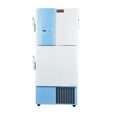
Thermo Forma
Thermo Forma 900 Series Operating instructions
Thermo Forma
Thermo Forma 8600 Series Operating instructions

Thermo Forma
Thermo Forma Power Plus 8500 Series Operating instructions

Thermo Forma
Thermo Forma 8523 Operating instructions
