Thermo Forma 8600 Series Operating instructions

8600 Series
Ultra Low Temperature
Upright Freezers
Operating and Maintenance Manual
Manual No: 7008602 Rev. 0
Model 8600 Series _______________________________________________________________________________
i
Read This Instruction Manual.
Failure to read, understand and follow the instructions in
this manual may result in damage to the unit, injury to operat-
ing personnel, and poor equipment performance.
CAUTION! All internal adjustments and maintenance must
be performed by qualified service personnel.
Refer to the serial tag on the back of this manual.
The material in this manual is for information purposes only.
The contents and the product it describes are subject to change
without notice. Thermo Forma makes no representations or war-
ranties with respect to this manual. In no event shall Thermo
Forma be held liable for any damages, direct or incidental, aris-
ing out of or related to the use of this manual.
MANUAL NUMBER 7008602
0 -- 1/10/03 Original Manual aks
REV ECR/ECN DATE DESCRIPTION By
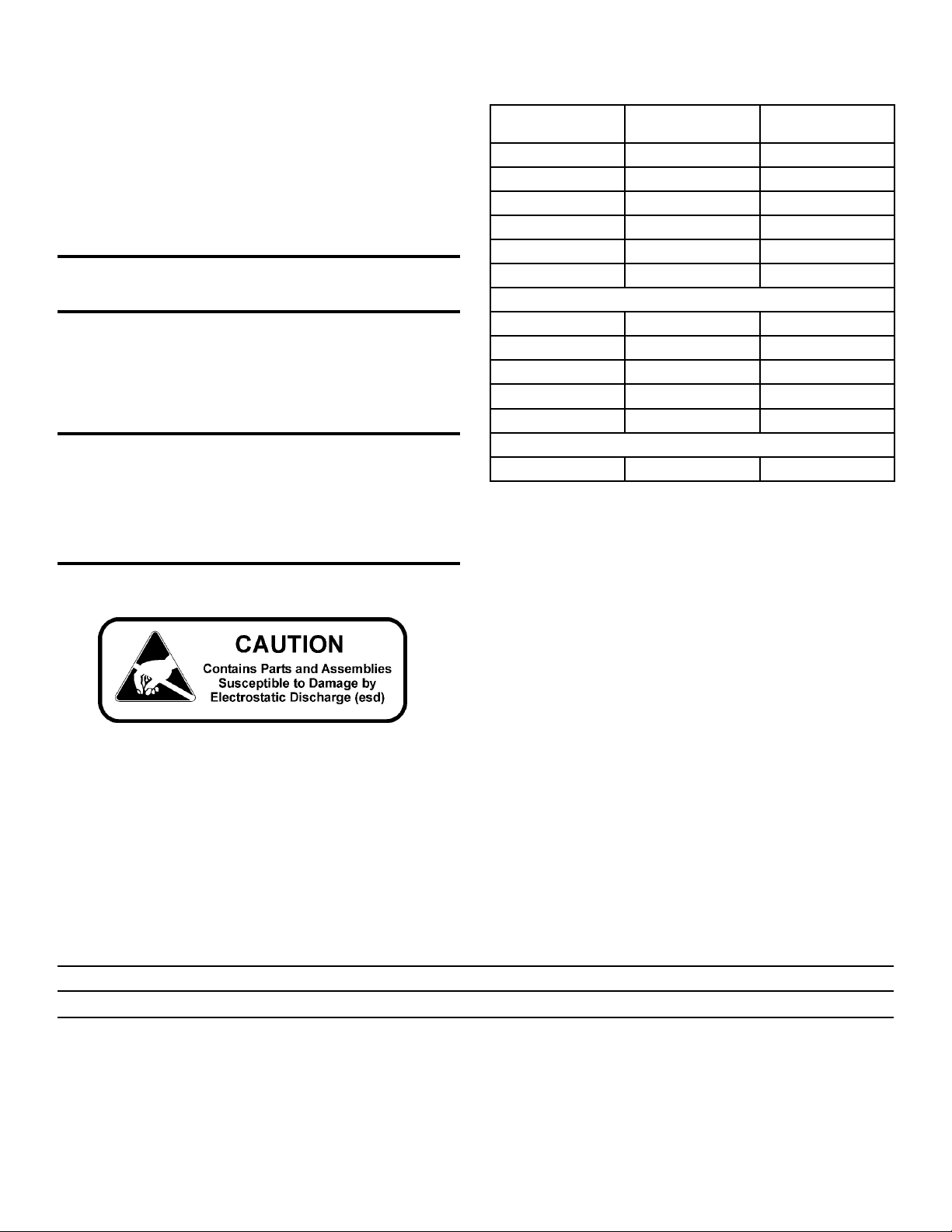
Models Capacity in
Cubic Feet
Voltage
8602 13 230
8603 13 120
8604 17 120
8605 17 230
8606 23 230
8607 28 230
Double Door Units
8691 13 230
8692 13 120
8693 17 120
8694 17 230
8695 23 230
Red Cell Storage
8627 13 230
Model 8600 Series _________________________________________________________________________Warnings
ii
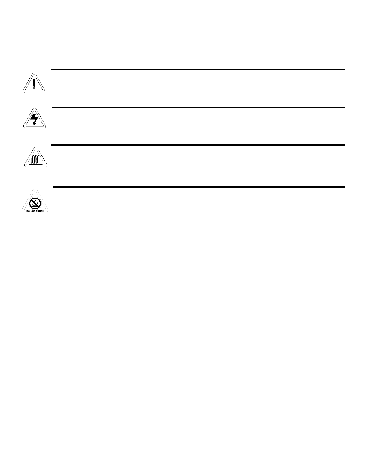
Important operating and/or maintenance instructions. Read the accompanying text carefully.
Potential electrical hazards. Only qualified persons should perform procedures associated with this symbol.
Hot surface(s) present which may cause burns to unprotected skin or to materials which may be damaged by elevated
temperatures
Extreme temperature hazards, hot or cold. Use special handling equipment or wear special, protective clothing.
√ Always use the proper protective equipment (clothing, gloves, goggles, etc.)
√ Always dissipate extreme cold or heat and wear protective clothing.
√ Always follow good hygiene practices.
√ Each individual is responsible for his or her own safety.
Model 8600 Series ___________________________________________________________________________Service
iii

Model 8600 Series __________________________________________________________________Table of Contents
iv
Table of Contents
Section 1 - Installation and Start-up . . . . . . . . . . . . . . .1 - 1
1.1 Freezer Components . . . . . . . . . . . . . . . . . . . . . . . . .1 - 1
1.2 Control Panel Keys, Displays and Indicators . . . . . .1 - 2
1.3 Operation of the Keypad . . . . . . . . . . . . . . . . . . . . . .1 - 3
1.4 Displays . . . . . . . . . . . . . . . . . . . . . . . . . . . . . . . . . .1 - 3
1.5 Installing the Freezer . . . . . . . . . . . . . . . . . . . . . . . . .1 - 3
a. Choosing the Location . . . . . . . . . . . . . . . . . . . . .1 - 4
b. Installing the Wall Bumpers . . . . . . . . . . . . . . . . .1 - 4
c. Installing the Shelves . . . . . . . . . . . . . . . . . . . . . .1 - 4
d. RS-232 Communications . . . . . . . . . . . . . . . . . . . .1 - 4
e. Remote Alarm Contacts and Analog Output . . . . .1 - 5
f. Attaching the Power Cord . . . . . . . . . . . . . . . . . . .1 - 5
g. Connecting the Unit to Electrical Power . . . . . . . .1 - 5
1.6 Freezer Start-Up . . . . . . . . . . . . . . . . . . . . . . . . . . . . .1 - 5
a. Setting the Operating Temperature . . . . . . . . . . . .1 - 5
b. Setting the High Temperature Alarm . . . . . . . . . . .1 - 6
c. Setting the Low Temperature Alarm . . . . . . . . . . .1 - 6
e. Access Code . . . . . . . . . . . . . . . . . . . . . . . . . . . . . .1 - 6
1.7 Run Mode . . . . . . . . . . . . . . . . . . . . . . . . . . . . . . . . . .1 - 6
Chart 1-1 . . . . . . . . . . . . . . . . . . . . . . . . . . . . . . . . . . . . . .1 - 7
Section 2 - Calibrate . . . . . . . . . . . . . . . . . . . . . . . . . . . .2 - 1
2.1 Calibrate Mode . . . . . . . . . . . . . . . . . . . . . . . . . . . . . .2 - 1
a. Calibrating the Control Probe . . . . . . . . . . . . . . . .2 - 1
b. Calibrating The Optional Sample Probe . . . . . . . .2 - 1
Chart 2-1 . . . . . . . . . . . . . . . . . . . . . . . . . . . . . . . . . . . . . .2 - 2
Section 3 - Configuration . . . . . . . . . . . . . . . . . . . . . . . .3 - 1
3.1 Configuration Mode . . . . . . . . . . . . . . . . . . . . . . . . . .3 - 1
a. High Alarm Test . . . . . . . . . . . . . . . . . . . . . . . . . .3 - 1
b. Low Alarm Test . . . . . . . . . . . . . . . . . . . . . . . . . .3 - 1
c. System Battery Test . . . . . . . . . . . . . . . . . . . . . . .3 - 1
d. BUS Battery Test . . . . . . . . . . . . . . . . . . . . . . . . .3 - 1
e. Display Temperature . . . . . . . . . . . . . . . . . . . . . . .3 - 1
f. Clear High Stage Alarm . . . . . . . . . . . . . . . . . . . . .3 - 1
g. Setting an Access Code . . . . . . . . . . . . . . . . . . . . .3 - 2
h. RS-485 Address . . . . . . . . . . . . . . . . . . . . . . . . . .3 - 2
i. Back Up System Type . . . . . . . . . . . . . . . . . . . . . .3 - 2
3.2 The RS-232 Configuration . . . . . . . . . . . . . . . . . . . . . .3 - 2
Section 4 - Alarms . . . . . . . . . . . . . . . . . . . . . . . . . . . . . .4 - 1
4.1 Alarms . . . . . . . . . . . . . . . . . . . . . . . . . . . . . . . . . . . .4 - 1
a. Wrong Power Alarm . . . . . . . . . . . . . . . . . . . . . . . .4 - 1
b. High Stage System Failure Alarm . . . . . . . . . . . . .4 - 1
c. Multiple Alarms . . . . . . . . . . . . . . . . . . . . . . . . . . .4 - 1
4.2 Probe Failure Alarms . . . . . . . . . . . . . . . . . . . . . . . . .4 - 1
Section 5 - Maintenance . . . . . . . . . . . . . . . . . . . . . . . . .5 - 1
5.1 Cleaning the Cabinet Exterior . . . . . . . . . . . . . . . . . .5 - 1
5.2 Cleaning the Air Filter . . . . . . . . . . . . . . . . . . . . . . . .5 - 1
5.3 Cleaning the Condenser . . . . . . . . . . . . . . . . . . . . . . .5 - 1
a. Cleaning the Water-cooled Condenser . . . . . . . . . .5 - 1
5.4 Defrosting the Chamber . . . . . . . . . . . . . . . . . . . . . . .5 - 1
5.5 Cleaning the Door Gasket . . . . . . . . . . . . . . . . . . . . .5 - 2
5.6 Cleaning the Vacuum Relief Port . . . . . . . . . . . . . . . .5 - 2
5.7 Replacing the Battery(s) . . . . . . . . . . . . . . . . . . . . . .5 - 2
5.8 Preparing the Unit for Storage . . . . . . . . . . . . . . . . . .5 - 2
Preventive Maintenance . . . . . . . . . . . . . . . . . . . . . . . . . .5 - 3
Section 6 - Factory Options . . . . . . . . . . . . . . . . . . . . . .6 - 1
6.1 BUS (Back Up System) . . . . . . . . . . . . . . . . . . . . . . .6 - 1
a. Installing the vent stack, solenoid and injection
assembly . . . . . . . . . . . . . . . . . . . . . . . . . . . . . . . .6 - 1
b. Installing the Temperature Probe . . . . . . . . . . . . . .6 - 2
c. Connecting the probe/solenoid harness . . . . . . . . .6 - 2
d. BUS Control Panel . . . . . . . . . . . . . . . . . . . . . . . .6 - 3
e. Setting the Optional BUS Set Point . . . . . . . . . . . .6 - 3
f. System Operation Check . . . . . . . . . . . . . . . . . . . .6 - 3
g. Cleaning the Vent Stack . . . . . . . . . . . . . . . . . . . . .6 - 3
h. Disconnecting the fitting assembly and
transfer hose . . . . . . . . . . . . . . . . . . . . . . . . . . . . .6 - 3
6.2 Chart Recorder . . . . . . . . . . . . . . . . . . . . . . . . . . . . . .6 - 4
a. Installing the chart paper . . . . . . . . . . . . . . . . . . .6 - 4
c. Recorder Calibration . . . . . . . . . . . . . . . . . . . . . . .6 - 4
6.3 Datalogger . . . . . . . . . . . . . . . . . . . . . . . . . . . . . . . . .6 - 5
6.4 Water-Cooled condenser . . . . . . . . . . . . . . . . . . . . . . .6 - 5
6.5 Five Inner Door Option . . . . . . . . . . . . . . . . . . . . . . .6 - 5
Section 7 - Specifications . . . . . . . . . . . . . . . . . . . . . . . . .7 -1
Section 8 - Spare Parts . . . . . . . . . . . . . . . . . . . . . . . . . .8 - 1
Section 9 - Refrigeration Schematics . . . . . . . . . . . . . .9 - 1
Section 10 - Electrical Schematics . . . . . . . . . . . . . . .10 - 1
Section 11 - Warranty . . . . . . . . . . . . . . . . . . . . . . . . .11 - 1
Appendix A - Handling Liquid Nitrogen . . . . . . . . . . . .A - 1
Appendix B - Handling Liquid CO2. . . . . . . . . . . . . . .B - 1
First Aid . . . . . . . . . . . . . . . . . . . . . . . . . . . . . . . . . . . . . .C - 1

Section 1 - Installation and Start-up
Model 8600 Series ___________________________________________________________________Installation and Start-Up
1 - 1
Figure 1-1
Model 8600 Series Front
Figure 1-2
Model 8600 Series Rear
1.1 Freezer Components
Figure 1-1
• Control Panel - keypad, displays and indicators.
• BUS (Optional Back Up System) panel.
• Optional temperature recorder - 7 day, one pen or datalog-
ger.
• Documentation compartment - storage of user’s manual
and other documentation.
Figure 1-2
• Remote alarm contacts and selectable analog output con-
nection - 0-1V, 4-20mA (default), 0-5V).
• Power inlet for power cord connection.
• Optional BUS connections for probe and solenoid.
• RS-232 (default) or RS-485 interface.
• Power Switch (mains disconnect).
Figures 1-3 and 1-4
• Vacuum relief port - pressure equalization port.
• Probe cover - houses control, optional recorder or datalog-
ger and 1535 alarm (optional) probes.
Figure 1-4
Vacuum Relief and Probe Cover Location
Figure 1-3
Vacuum Relief Port and Probe Cover
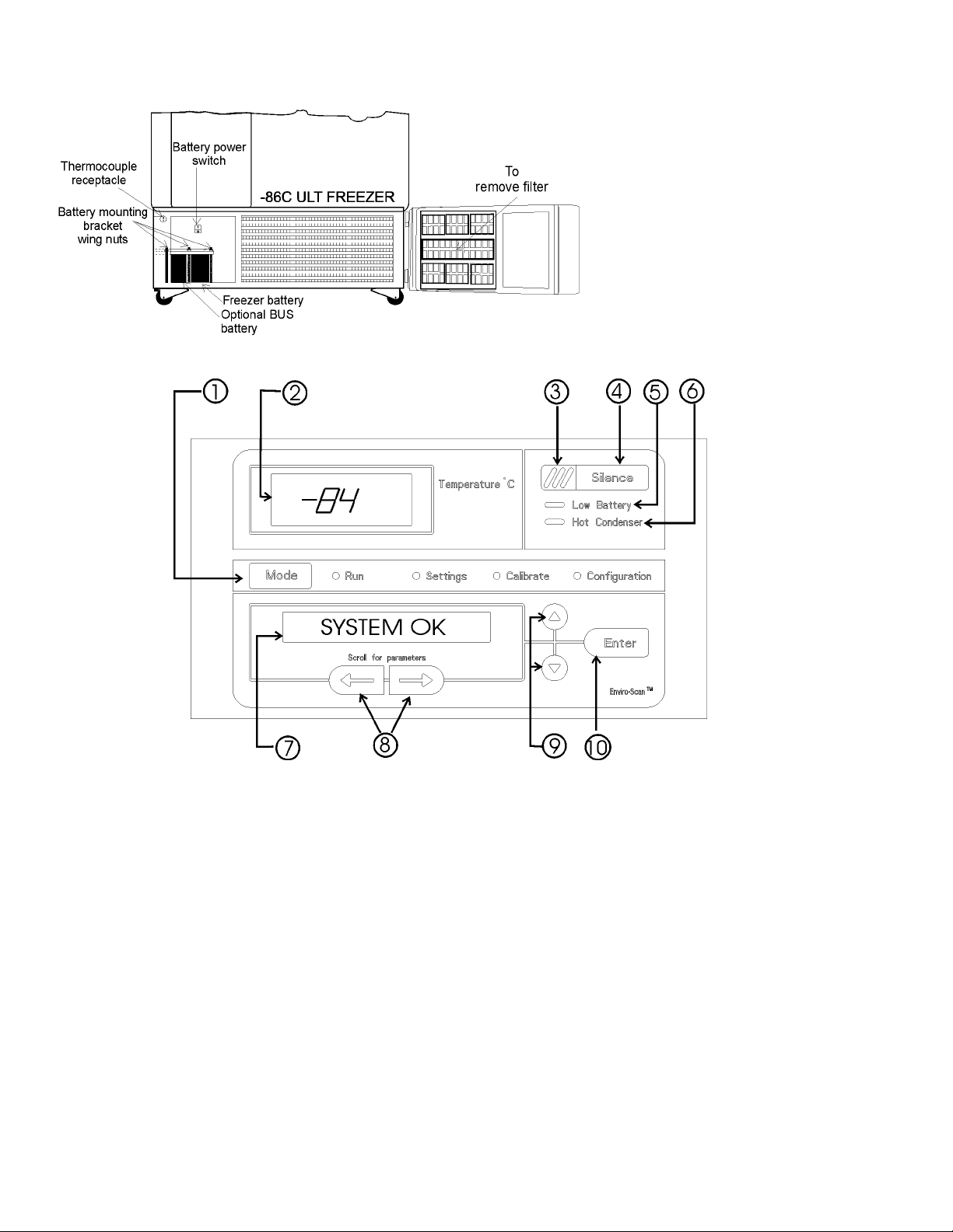
1.2 Control Panel Keys, Displays and Indicators
(See Figure 1-6)
1. Mode Select Switch - Used to select Run, Settings,
Calibrate and System Configuration Modes.
Mode Select Indicators -
Run: Run Menu
Settings: Set Points Menu
Calibrate: Calibrate Menu
Configuration: Configuration Menu
2. Temperature Display - Displays temperature in degrees
Celsius.
3. Alarm Indicator - Light pulses on/off during an alarm
condition of the cabinet.
4. Silence - Silences the audible alarm.
5. Low Battery - indicates a low battery condition of the
freezer battery.
6. Hot Condenser - indicates a hot condenser condition.
7. Message Center - displays system status and alarms.
8. Scroll for Parameters Arrows - moves the operator
through the choices of the selected mode.
9. Up and Down Arrows - Increases or decreases values,
toggles between choices.
10. Enter - Stores the value into computer memory.
Figure 1-6, Control Panel
1 - 2
Model 8600 Series ____________________________________________________________Installation and Start-Up
Figure 1-5
Battery(s) location and Switch
Figure 1-5
• Battery mounting bracket wing nuts
(three).
• Battery power switch (freezer and BUS).
• Freezer battery.
• Optional BUS battery.
• Freezer filter location.
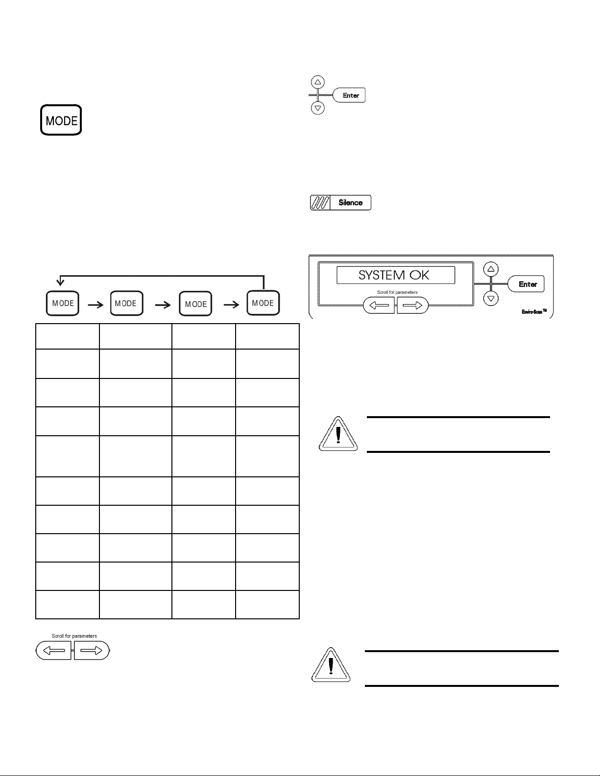
1.3 Operation of the Keypad
The 8600 Series freezer has four basic modes
which allow freezer setup: Run, Settings,
Calibrate and Configuration.
Run is the default mode which the freezer will normally be
in during operation.
Settings is used to enter system set points for freezer oper-
ation.
Calibrate is used to calibrate various system parameters.
Configuration allows for custom setup of various options.
The chart below shows the selections under each of the
modes.
Scroll for Parameters Arrows: Steps the
operator through the parameters of SET-
TINGS, CALIBRATE and CONFIGURA-
TION Modes. The right arrow goes to the
next parameter, the left arrow returns to the
previous parameter.
Up Arrow: Increases or toggles the parameter
value that has been selected in the SETTINGS,
CALIBRATE, and CONFIGURATION Modes.
Enter: Must press Enter key to save to memo-
ry all changed values.
Down Arrow: Decreases or toggles the param-
eter values that have been selected in the SET-
TINGS, CALIBRATE and CONFIGURATION
Modes.
Silence Key: Press to silence the audible
alarm. See Section 4 for alarm ringback times.
1.4 Displays
Message Center: Displays the system status (Mode) at all
times. Displays SYSTEM OK during normal operation,
or alarm messages if the system detects an alarm condi-
tion. See Section 4.1- Alarms.
1.5 Installing the Freezer
To remove the freezer from the pallet, use
the 7/16" wrench to remove all the bolts securing the shipping
bracket to the pallet.
Remove the shipping bracket. Remove the ramp
boards from the pallet and place the slotted end over the ramp
brackets on the pallet. The support blocks on the ramps will be
facing down. Before moving the freezer, make sure the casters
are unlocked and moving freely. Align the caster with the ramp
boards. Use adequate personnel to roll the freezer off the pallet.
The freezer can be easily pushed to the desired
approved location, described in Section 1.5.a. If necessary, the
doors and lower front panel may be opened to move the unit
through tight openings. When the freezer is in position, set the
front caster brakes.
Model 8600 Series ___________________________________________________________________Installation and Start-Up
1 - 3
If tipped more than 45°, allow the unit to set
upright for 24 hours before start up.
The freezer must not be moved with the prod-
uct load inside.
RUN SETTINGS CALIBRATE CONFIGU-
RATION
Default Mode
SYSTEM OK
Control Set Point Control Probe High Alarm
Test
LINE VOLT-
AGE
High Alarm Set
Point
Optional
Sample Probe
Low Alarm
Test
COMPENSAT-
ED VOLTAGE
Low Alarm Set
Point
System Battery
Test
HSHX TEM-
PERATURE
Optional Back
Up System Set
Point
BUS Battery
Test
Display
Temperature
Clear High
Stage Alarm
Set Access
Code
RS485
Address
BUS type CO2
or LN2
a. Choosing the Location
Locate the freezer on a firm, level surface in an area with
an ambient temperature between 18°C and 32°C. Provide ample
room to reach the mains disconnect switch (power switch)
located on the rear of the freezer.
b. Installing the Wall Bumpers
The parts bag, located inside the cabinet, contains the fol-
lowing parts.
Install the bolts into the pre-tapped holes on the back of the
compressor section. Install a neoprene cap on each bolt. Refer
to Figure 1-2 for the locations of the pre-tapped holes.
c. Installing the Shelves
Install the shelf clips into the shelf pilasters (front and
back) at the desired shelf level. Install the shelves in the cabinet
onto the clips.
NOTE: On units having the optional 5 inner door option, refer
to the instructions accompanying the inner door kit.
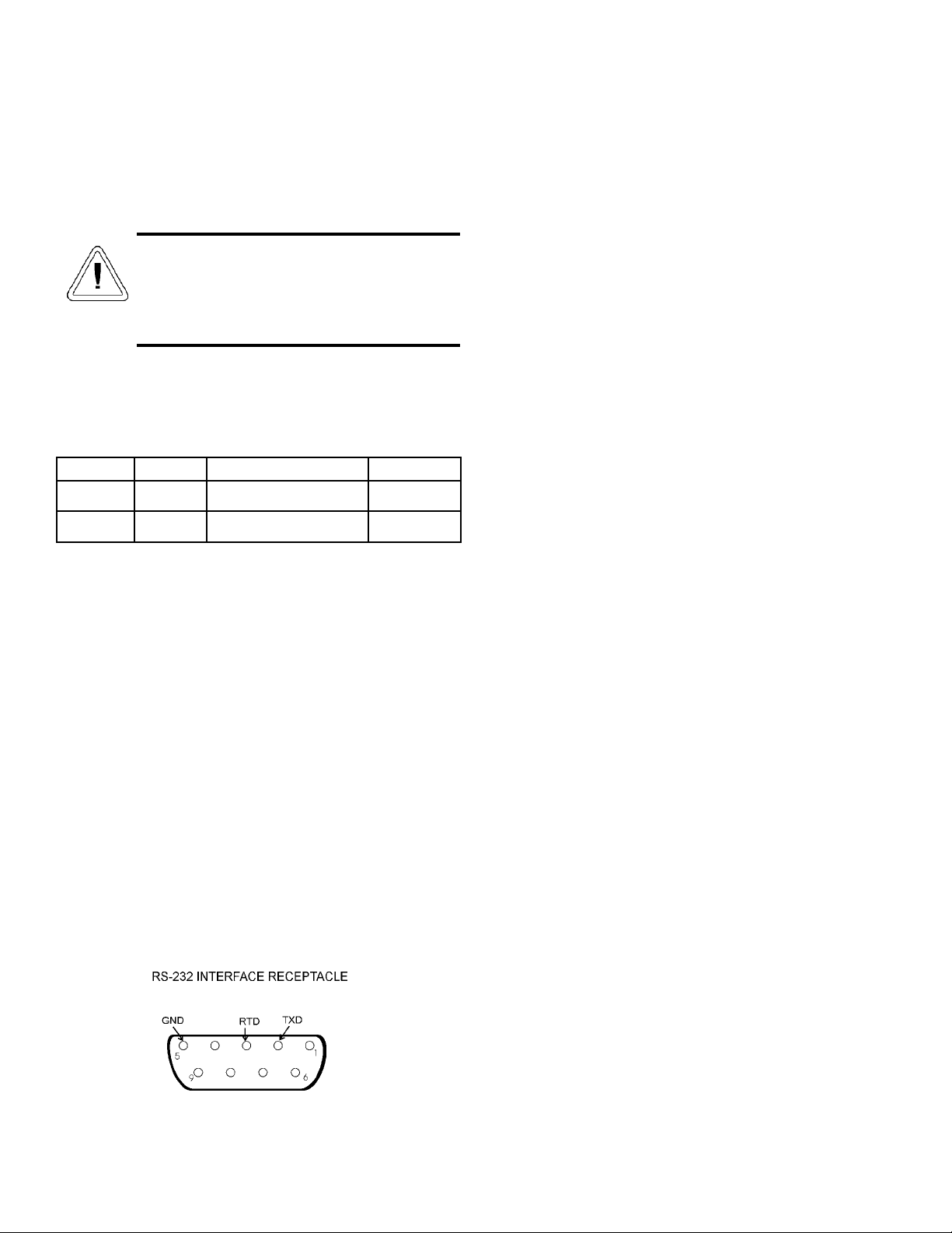
d. RS-232 Communications
The 8600 series freezer has a data communications interface.
The factory default setting is RS-232.
The wiring identification for the interface is shown in
Figure 1-7. One nine pin, sub "D" style connector is located on
the back of the freezer. See Figure 1-2 for the location of the
connector on the freezer.
The freezer transmits temperature information one
minute after power is first applied to the unit, then every 60
minutes thereafter.
Data format:
Baud 1200
Data bits 8 (7 bit ASCII with leading zero)
Start bits 1
Stop bits 2
Parity none
The data transfer sequence is transmitted in the follow-
ing format. X refers to numerical temperature data.
(NUL) (-) XXX (SP) C (SP) (OVERTEMP) (SP) (LF) (CR)
(EOT) (SP) (UNDER TEMP)
The words "OVER TEMP" or "UNDER TEMP" are
transmitted when an alarm condition exists along with the tem-
perature. If no alarm condition exists, spaces will be sent. A
total of 20 characters will be sent.
SP - Space LF - Line feed
CR - Carriage return EOT - End of text (4)
NUL - Null character (00)
Model 8600 Series ___________________________________________________________________Installation and Start-Up
1 - 4
Quantity Stock # Description Purpose
2510016 1/4-20 x 5-1/2” Bolt Wall Bumper
2 380520 Neoprene Cap Cap Protector
Figure 1-7
For proper ventilation and airflow, a minimum
clearance of 5” at the rear and top and a clear-
ance of 8” on the side of the freezer is required.
Allow adequate space in the front of the freezer
for door opening.
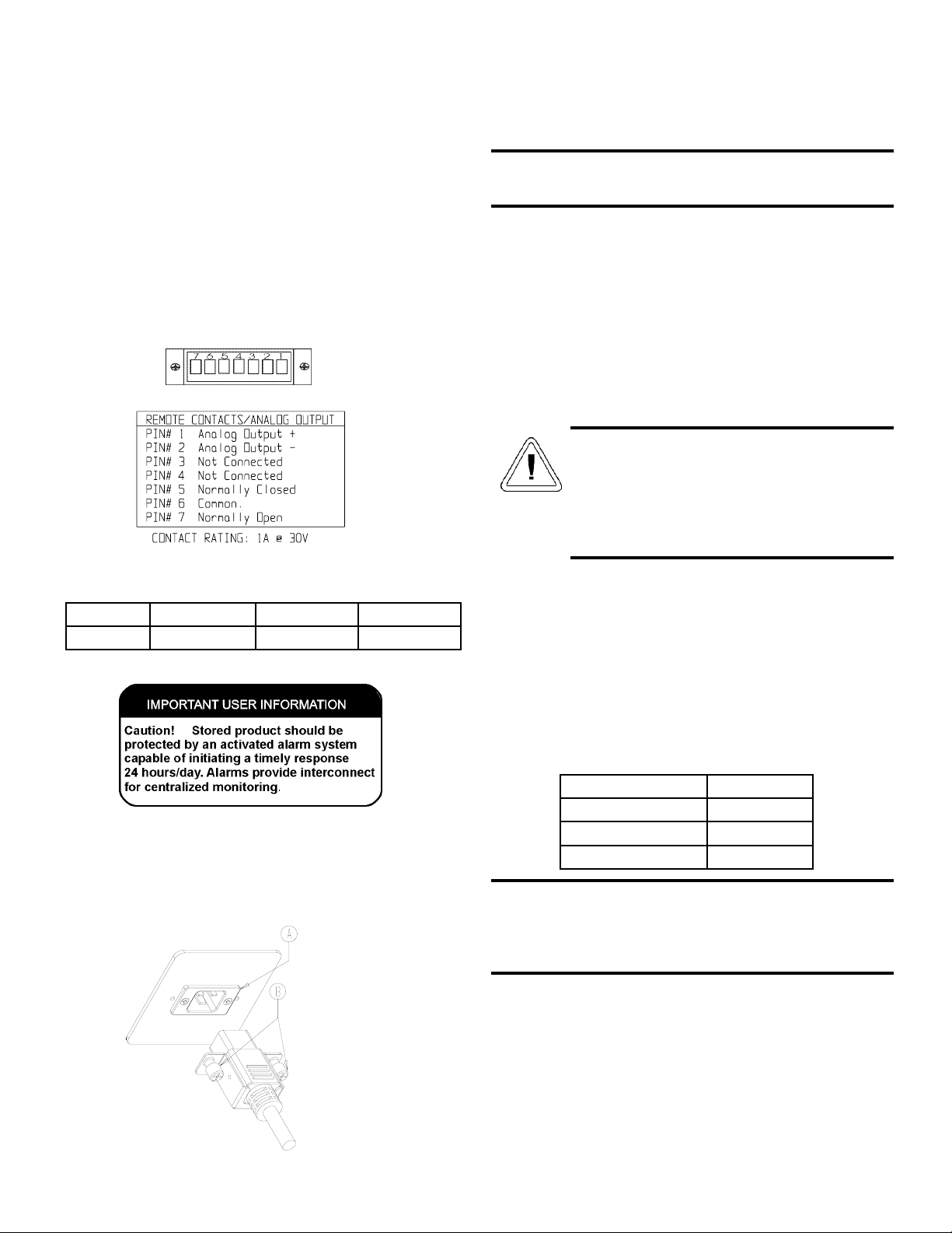
e. Remote Alarm Contacts and Analog Output
The 8600 series freezer has remote alarm contacts and ana-
log output. The remote alarm provides a NO (normally open)
output, a NC (normally closed) output and COM (common).
The contacts will trip on a power outage, high temperature
alarm or low temperature alarm.
The pin configuration for the remote contacts/analog output
is shown below (in alarm state). The analog output function
allows the freezer to output signals representing the temperature
of the freezer cabinet. The factory default setting is 4-20 mA.
Refer to figure 1-9 for output specifications.
f. Attaching the Power Cord
Insert the power cord into the power outlet module (A).
Tighten screws (B) on the power cord retainer.
g. Connecting the Unit to Electrical Power
See the serial tag on the side of the unit for electrical specifi-
cations or refer to the electrical schematics in this manual.
The freezer should be operated on a dedicated grounded
service. Check the voltage rating on the serial tag of the unit
and compare it with the outlet voltage. Then, with the power
switch turned off, plug the line cord into the wall outlet.
First turn on the freezer power switch. Then open the lower
front door by grasping the bottom left corner. Locate the battery
switch and turn it on. See Figure 1-5. During initial freezer
start-up, the system battery may require charging and the Low
Battery message may appear in the message center.
1.6 Freezer Start-Up
With the freezer properly installed and connected to power,
system set points can be entered. The following set points can
be entered in Settings mode: Control temperature, high temper-
ature alarm set point, low temperature alarm set point, and
(optional) BUS set point. Default settings are shown in the table
below. See Chart 1-1 for more detail.
a. Setting the Operating Temperature
All 8600 Series freezers have an operating temperature
range of -50°C to -86°C, depending on ambient temperature.
The freezer is shipped from the factory with a temperature set
point of -80°C. To change the operating temperature set point:
1. Press the Mode key until the Settings indicator lights.
Model 8600 Series ____________________________________________________________Installation and Start-Up
Figure 1-10
1 - 5
If the set point is changed and the low temperature and high
temperature alarms are set 10° from the set point, the alarm
set points will be adjusted automatically to maintain a dis-
tance of at least 10° from set point.
Control Set Point -80°C
High Temperature Alarm -70°C
Low temperature alarm -90°C
Optional BUS Set Point -60°C
4-20 mA 0-1V 0-5V
Temperature -100 to +50°C -100 to +50°C -100 to +50°C
Figure 1-9
Assure the battery switch is turned on. The
rechargeable batteries require 36 hours to charge
at initial start-up. A “Low Battery” alarm may
occur until the batteries are fully charged. Should
a power failure occur during the initial start-up
period, the electronics will have limited operation.
Figure 1-8

1 - 6
Model 8600 Series ____________________________________________________________Installation and Start-Up
2. Press the right arrow until “SET PT = -XX” is displayed
in the message center.
3. Press the up/down arrow key until the desired tempera-
ture set point is displayed.
4. Press Enter to save the set point.
5. Press the Mode key until the Run indicator lights for
Run mode or press the right/left arrow keys to go to
next/previous parameter.
If no control keys are pressed, the freezer will automatical-
ly return to RUN mode after 5 minutes.
b. Setting the High Temperature Alarm
The high temperature alarm will activate an audible/visual
warning when the freezer chamber temperature has reached or
exceeded the high temperature alarm set point.
To set the high temperature alarm set point:
1. Press the Mode key until the Set indicator lights.
2. Press the right arrow until “HI ALM = -XX” is dis-
played in the message center.
3. Press the up or down arrow key until the desired high
temperature alarm set point is displayed.
4. Press Enter to save the setting.
5. Press the Mode key until the Run indicator lights or
press the right or left arrow to go to the next or previous
parameter.
If no control keys are pressed, the freezer will automatical-
ly return to RUN mode after 5 minutes.
Note: The high alarm set point must be set at least 10°C from
the control set point.
c. Setting the Low Temperature Alarm
The low temperature alarm will activate an audible/visual
warning when the freezer chamber temperature has reached or
decrease below the low temperature alarm set point.
To set the low temperature alarm set point:
1. Press the Mode key until the Settings indicator lights.
2. Press the right arrow until “LO ALM = -XX” is dis-
played in the message center.
3. Press the up or down arrow key until the desired low
temperature alarm set point is displayed.
4. Press Enter to save the setting.
5. Press the Mode key until the Run indicator lights or
press the right or left arrow to go to the next or previous
parameter.
If no control keys are pressed, the freezer will automatical-
ly return to RUN mode after 5 minutes.
Note: The low alarm set point must be set at least 10°C from
the control set point.
d. Access Code
An access code of 000 is required to access the Settings,
Calibrate or Configuration modes. If the access code is not at
the default 000, you can not leave RUN mode without entering
a code. See section 3.1.d for instructions on modifying the
access code.
1.7 Run Mode
The Run mode is the default mode for the freezer. The run
mode will display the cabinet temperature on the temperature
display and ‘SYSTEM OK’ on the message center under nor-
mal operating conditions. In addition, the Run mode allows dis-
play of the following information:
LINE VOLTAGE
COMPENSATED VOLTAGE
HSHX TEMPERATURE (heat exchanger temperature)
This information is scrolled individually by pressing the
right arrow key. In each case, the message center returns to
SYSTEM OK in 10 seconds if no keys are pressed.

Model 8600 Series ____________________________________________________________Installation and Start-Up
1 - 7

Section 2 - Calibrate
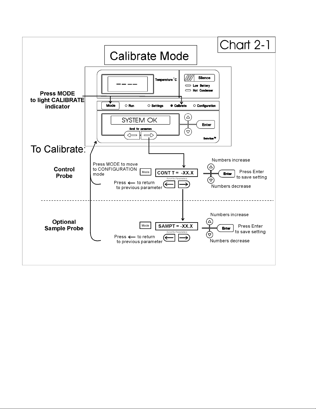
2.1 Calibrate Mode
Once the freezer has stabilized, the control or sample probe
may need to be calibrated. Calibration frequency is dependent
on use, ambient conditions and accuracy required. A good labo-
ratory practice would require at least an annual calibration
check. On new installations, all parameters should be checked
after the stabilization period.
Before making any calibration or adjustments to
the unit, it is imperative that all reference instru-
ments be properly calibrated.
a. Calibrating the Control Probe
Plug a type T thermocouple reader into the receptacle
located inside the lower door (see Figure 1-5). Compare the
control temperature set point to the temperature of the measur-
ing device. See Chart 2-1 at the end of this section for more
detail.
1. Press the Mode key until the Calibrate indicator lights.
2. Press the right arrow until “CONT T = -XX.X” appears
in the message center.
3. Press up/down arrow to match the display to calibrated
instrument.
4. Press Enter to store calibration.
5. Press the Mode key to return to Run or the right/left
arrow to go to next/previous parameter.
b. Calibrating the Optional Sample Probe
For freezers with the optional sample probe, place the cali-
brated instrument in the center of the sample bottle. The bottle
should contain an appropriate medium and the measuring
instrument should be centered in the bottle.
1. Press the Mode key until the Calibrate indicator lights.
2. Press the right arrow until “SAMP T = -XX.X” appears
in the message center.
3. Press up/down arrow to match display to calibrated
instrument.
4. Press Enter to store calibration.
5. Press the Mode key to return to Run or the right/left
arrow to go to next/previous parameter.
See Chart 2-1 for calibration process functions.
Temperature Stabilization Periods
Startup - Allow 12 hours for the temperature in the cabinet to
stabilize before proceeding.
Already Operating - Allow at least 2 hours after the display
reaches set point for temperature to stabilize before proceeding.
During calibration, the temperature display will not be avail-
able.
If no keys are pressed for approximately five minutes while
in calibration mode, the system will reset to Run mode.
Model 8600 Series _________________________________________________________________________Calibration
2 - 1
Model 8600 Series ________________________________________________________________________Calibration
2 - 2

cator will light. Press the Silence key and the alarm indicator
will go off. The Low Battery light will stay on until a future
battery test is performed and passed.
d. BUS Battery Test
To test the charge of the BUS battery:
1. Press the Mode key until the Configuration indicator
lights.
2. Press the right arrow until BUS BAT TEST is displayed
in the message center.
3. Press Enter to initiate the test.
TESTING BATT will display during the testing period.
Upon completion of the test the message center will display
BBAT GOOD or BBAT FAIL When a test is failed, the audible
alarm will sound, the alarm indicator and the Low Battery indi-
cator will light. Press the Silence key and the alarm indicator
will go off. The Low Battery light will stay on until a future
battery test is performed and passed.
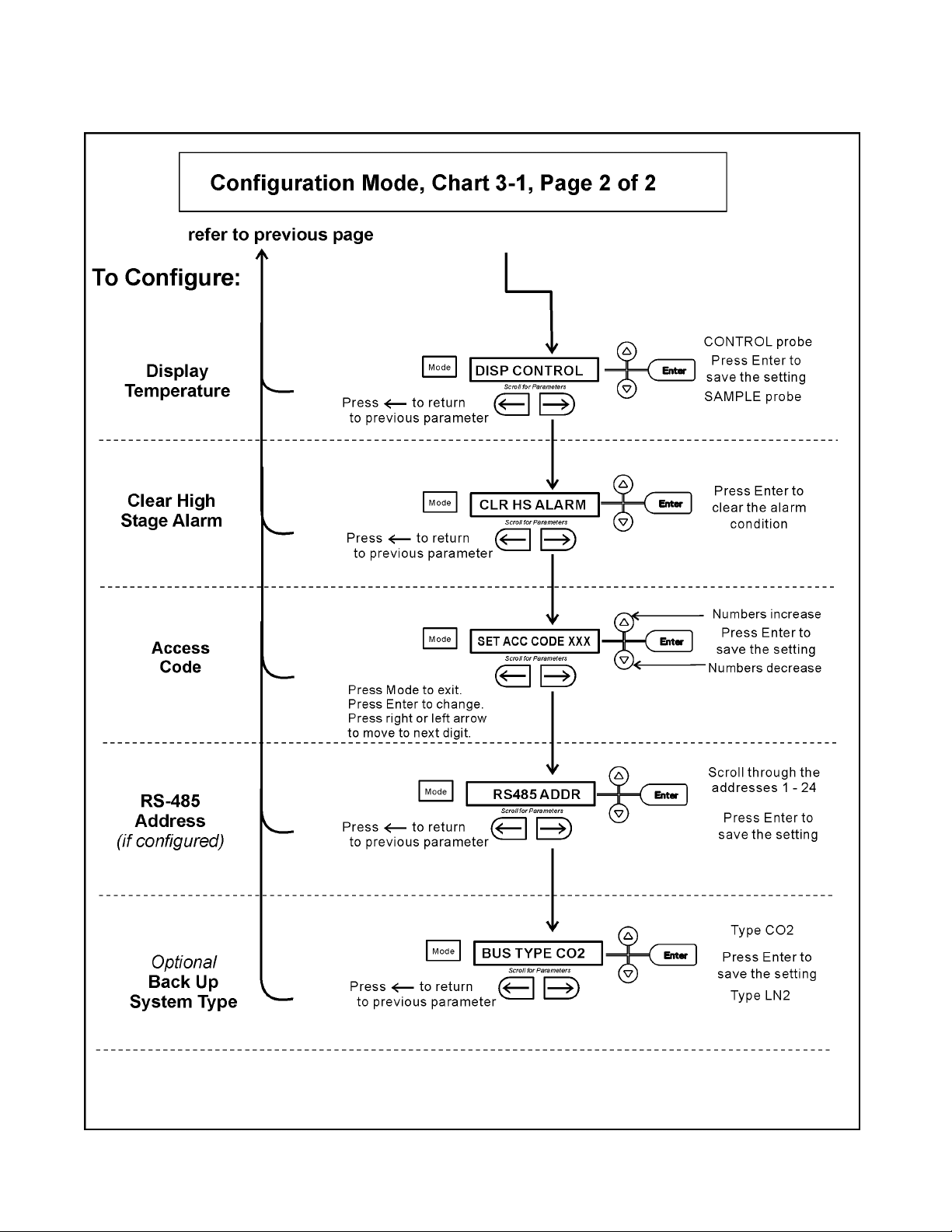
e. Display Temperature
This function, only available on freezers with the
optional sample probe, allows the user to select which tempera-
ture is displayed in the temperature display window. The
options are CONTROL or SAMPLE.
1. Press the Mode key until the Configuration indicator
lights.
2. Press the right arrow until DISP CONTROL or DISP
SAMPLE is displayed in the message center.
3. Press up/down arrow to toggle between the two display
selections.
4. Press Enter to save.
If control probe is selected, the temperature display
will be on continuously. If sample probe is selected, the temper-
ature display will be preceded with a letter ‘S’.
f. Clear High Stage Alarm
Should a high stage alarm occurred, it may become neces-
sary to the clear the alarm condition after the condition has
been corrected.
1. Press the Mode key until the Configuration indicator
lights.
2. Press the right arrow until CLR HS ALARM is dis-
played in the message center.
3. Press Enter to clear the alarm.
Model 8600 Series ______________________________________________________________________Configuration
3 - 1
Section 3 - Configuration
3.1 Configuration Mode
The Configuration Mode is used for testing and custom
setup of the freezer. The configuration functions listed and
described below may not be necessary in all applications, but
are available if needed. See Chart 3-1 for more detail.
a. High Alarm Test
The high alarm test is used to verify the high alarm will
activate, should the freezer temperature equal or exceed the
high alarm set point.
1. Press the Mode key until the Configuration indicator
lights.
2. Press the right arrow until HI ALRM TEST is displayed
in the message center.
3. Press Enter to initiate the test.
The temperature on the display will begin to increase until
the high alarm set point has been reached. The audible alarm
will sound and the alarm indicator will flash. Press the Silence
key to silence the alarm.
b. Low Alarm Test
The low alarm test is used to verify the low alarm will acti-
vate, should the freezer temperature equal or become less than
the low alarm set point.
1. Press the Mode key until the Configuration indicator
lights.
2. Press the right arrow until LO ALRM TEST is dis-
played in the message center.
3. Press Enter to initiate the test.
The temperature on the display will begin to decrease until
the low alarm set point has been reached. The audible alarm
will sound and the alarm indicator will flash. Press the Silence
key to silence the alarm.
c. System Battery Test
To test the charge of the freezer battery:
1. Press the Mode key until the Configuration indicator
lights.
2. Press the right arrow until SYS BAT TEST is displayed
in the message center.
3. Press Enter to initiate the test.
TESTING BATT will display during the testing period.
Upon completion of the test the message center will display
BATT GOOD or BATT FAIL When a test is failed, the audible
alarm will sound, the alarm indicator and the Low Battery indi-

i. Back Up System Type
This function, which is only available on freezers with the
optional BUS (back up system), allows the user to select which
type of gas is injected into the freezer chamber. The options are
CO2 and LN2.
1. Press the Mode key until the Configuration indicator
lights.
2. Press the right arrow until BUS TYPE CO2 or BUS
TYPE LN2 is displayed in the message center.
3. Press up/down arrow to toggle between the two display
selections.
4. Press Enter to save.
g. Setting an Access Code
To set the Access Code:
1. Press the Mode key until the Configuration indicator
lights.
2. Press the right arrow until “SET ACC CODE” is dis-
played in the message center.
3. Press Enter.
4. The message center will display ACC CODE = 000.
Press the up or down arrow key until the desired access
code is displayed (000 - 999). Press the left or right
arrow key to select digit 1, 2, 3.
The left and right arrow keys are used to move from the first
through the third digits within the access code.
5. Press Enter to save the setting
6. Press the Mode key until the Run indicator lights.A 3-
digit Access Code can be entered to avoid unauthorized
personnel from changing the set points, calibration, or
configuration. A setting of 000 will bypass the access
code. The factory setting is 000.
h. RS485 Address
If the freezer is configured for RS-485 communications, it
will need to have a unique identification address. This address
is set through the Configuration mode.
1. Press the Mode key until the Configuration indicator
lights.
2. Press the right arrow until RS485ADDR is displayed in
the message center.
3. Press Enter. The message center will display
485 ADDR XX.
4. Press up/down arrow to select the appropriate address
for the freezer (1 - 24).
4. Press Enter to save.
Model 8600 Series ______________________________________________________________________Configuration
3 - 2

Model 8600 Series _______________________________________________________________________Configuration
3 - 3
3 - 4
Model 8600 Series _______________________________________________________________________Configuration
Section 4 - Alarms
4.1 Alarms
The Model 8600 Series freezer alarm system is shown in the table below. When an alarm is active, the message appears in the
LED message center. Press the Silence key to disable the audible alarm for the ringback period. The visual alarm will continue until
the freezer returns to a normal condition. The alarms are momentary alarms only. When an alarm condition occurs and then returns
to normal, the freezer automatically clears the alarm condition and the message center.
Model 8600 Series ___________________________________________________________________________Alarms
4 - 1
a. Wrong Power Alarm
If a 230 V freezer is connected to a 120 V power source or a
120 V freezer is connected to a 230 V power source, the elec-
tronics will detect that an incorrect power source has been con-
nected to the freezer. Under this condition, the fans and com-
pressors will not turn on and an audible and visual alarm will
occur along with the "WRONG POWER" message in the LED
message center. The audible and visual alarms will remain until
the freezer is connected to the correct power source.
b. High Stage System Failure Alarm
This condition is created when the high stage compressor
and fans run for 30 minutes and are not capable of cooling the
interstage heat exchanger to the proper temperature. Under this
condition, the high stage compressor and fans will turn off after
30 minutes and an audible and visual alarm will occur along
with the "HS SYST FAIL" message in the LED message center.
c. Multiple Alarms
When multiple alarm conditions occur, active messages are
displayed in the message center one at a time, updating at 5 sec-
ond intervals. Pressing Silence during multiple alarms causes all
active alarms to be silenced and to ring back in 15 minutes.
4.2 Probe Failure Alarms
The microprocessor in 8600 series freezers continually
scans all probes including the control probe, heat exchanger
probe, condenser probe and optional sample probe to ensure that
they are operating properly. Should an error be detected, the
"PROBE # FAIL" alarm will occur as described in 4.1 above. If
an error is detected with the control probe (PROBE 1 FAIL), the
high and low stage compressors will run continuously. As a
result, the cabinet temperature will decrease until it reaches the
lowest temperature that the refrigeration system can maintain. If
an error is detected with the heat exchanger probe (PROBE 2
FAIL), the freezer will cycle properly at its temperature set point
using a 5 minute step start between the high and low stage com-
pressors. If an error is detected with the condenser probe
(PROBE 3 FAIL) or optional sample probe (PROBE 4 FAIL),
there is no impact on the performance of the freezer. However,
the hot condenser alarm may also occur when the condenser
probe fails. Contact the Thermo Forma Service Department (1-
888-213-1790) or your local distributor.
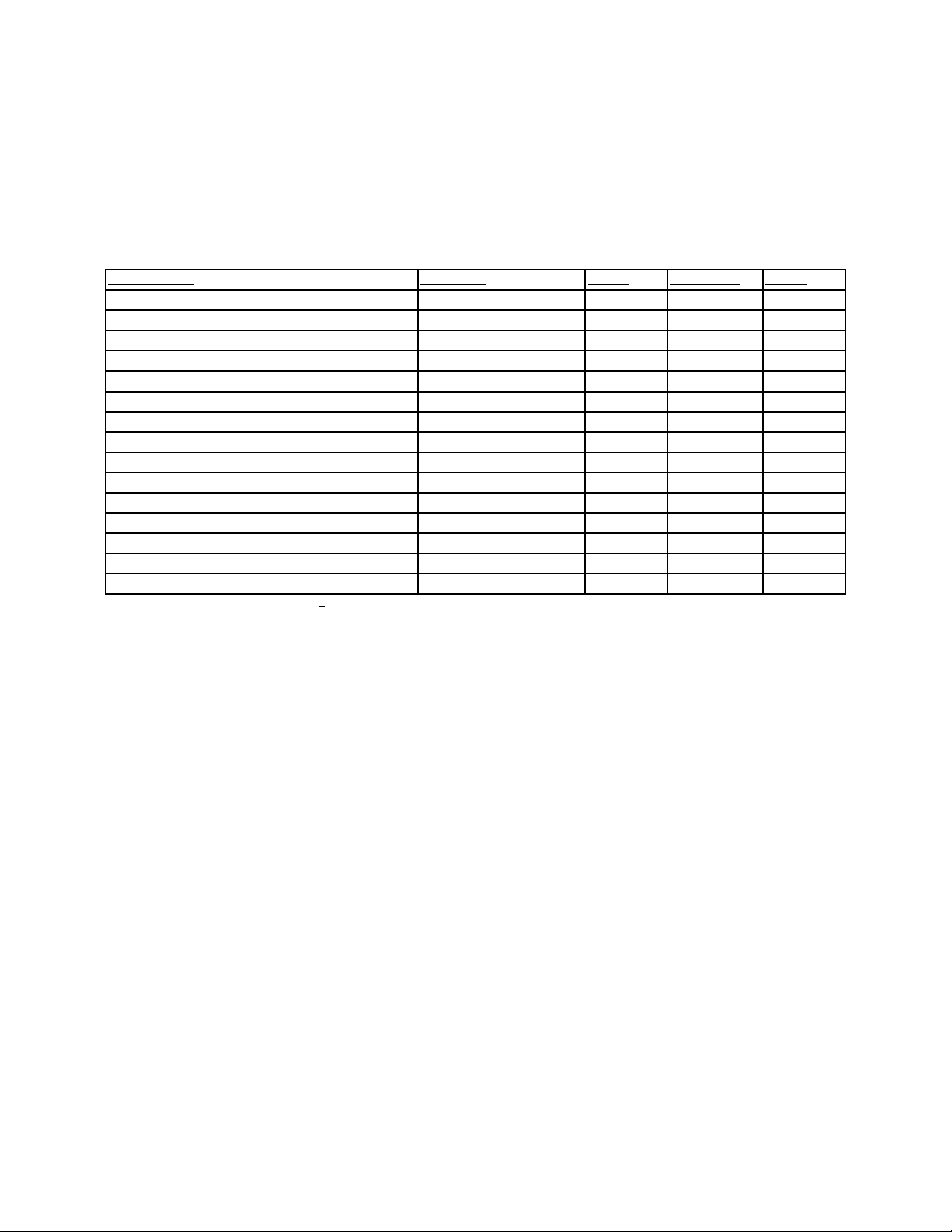
Description Message Delay Ringback Relay
No alarm condition exists SYSTEM OK ---- ---- ----
Power Failure POWER FAIL 1 min. 15 min. Yes
High Temperature Alarm TEMP IS HIGH 1 min. 15 min. Yes
Low Temperature Alarm TEMP IS LOW 1 min. 15 min. Yes
Door Ajar DOOR IS OPEN 1 min. 15 min. No
Low Battery LOW BATTERY 1 min. 12 hours No
Control Probe Failure - see 4.2 PROBE 1 FAIL 1 min. 15 min. No
Heat Exchanger Probe Failure - see 4.2 PROBE 2 FAIL 1 min. 15 min. No
Condenser Probe - see 4.2 PROBE 3 FAIL 1 min. 15 min. No
Sample Probe Failure (optional) - see 4.2 PROBE 4 FAIL 1 min. 15 min. No
High Stage System Failure HS SYST FAIL 1 min. 15 min. No
Condenser Hot Condition HOT CONDENSR 1 min. none No
Wrong Power WRONG POWER 0 min. none No
Filter Needs Cleaning CLEAN FILTER 0 min. 3 months No
Gasket Needs Cleaning CLEAN GASKET 0 min. 3 months No
All alarm delays and ringback times are +30 seconds.
Section 5 - Maintenance
5.1 Cleaning the Cabinet Exterior
Wipe down the freezer exterior using soap and water and
a general use laboratory disinfectant. Rinse thoroughly with
clean water and dry with a soft cloth.
5.2 Cleaning the Air Filter (minimum four times a
year*)
1. Open the front lower door by grasping the bottom left
corner.
2. Locate the grille on the door. See Figure 1-5. Grasp the
middle of the grille material and gently pull out to
remove.
3. Wash the filter material using water and a mild deter-
gent.
4. Dry by pressing between two towels.
5. Install the filter back into the grille and attach the grille.
* The clean filter alarm occurs every three months as a
reminder to clean the air filter. Depending upon environmental
conditions, the filter may need to be cleaned or replaced more
frequently. If the filter becomes torn or excessively dirty, a
replacement can be purchased from Thermo Forma. Order part
number 760203.
5.3 Cleaning the Condenser (minimum of twice a
year*)
1. Open the front lower door by grasping the bottom left
corner. See Figure 1-5.
2. Using a vacuum cleaner, exercising care to not damage
the condenser fins, clean the condenser.
* Depending upon environmental conditions, the condenser
may need to be cleaned more frequently.
a. Cleaning the Water-cooled Condenser
The water-cooled condenser can be cleaned-in-place by
using the CIP procedure. Cleaning solutions can be used,
depending on type of deposits or build-up to be removed.
Do not use liquids that are corrosive to stainless
steel or the brazing material (copper or nickel).
CIP (Clean-In-Place) Procedure
1. Disconnect the unit from the water supply.
2. Drain the unit.
3 . Rinse with fresh water and drain the unit again.
4. Fill with fresh water.
5. Add cleaning agent (solution and concentration depend-
ent on deposits or build-up).
6. Circulate cleaning solution (if feasible).
7. Drain the cleaning solution.
8. Add and circulate a passivating liquid for corrosion inhi-
bition of plate surfaces.
9. Drain this liquid.
10. Rinse with fresh water and drain.
11. Reconnect the water supply and fill the unit.
12 . Return to service.
5.4 Defrosting the Chamber
1. Remove all product and place it in another freezer.
2. Turn the unit off and disconnect it from the power
source.
3. Turn off the power switch (see figure 5-1) to the bat-
tery(s).
4. Open all of the doors and place towels on the chamber
floor.
5. Allow the frost to melt and become loose.
6. Remove the frost with a soft cloth.
7. After defrosting is complete, clean the interior with a
non-chloride detergent. Rinse thoroughly with clean
water and dry with a soft cloth.
8. Plug unit in and turn power switch on.
9. Turn the battery power switch to the on position.
10. Allow the freezer to operate empty overnight before
reloading the product.
Model 8600 Series ______________________________________________________________________Maintenance
5 - 1
Avoid the excessive use of water
around the control area due to the risk
of electrical shock. Damage to the con-
trols may also result.
This manual suits for next models
12
Table of contents
Other Thermo Forma Freezer manuals

Thermo Forma
Thermo Forma 3795 Operating instructions

Thermo Forma
Thermo Forma 8097 Operating instructions

Thermo Forma
Thermo Forma 8523 Operating instructions

Thermo Forma
Thermo Forma Power Plus 8500 Series Operating instructions

Thermo Forma
Thermo Forma 916 Operating instructions

Thermo Forma
Thermo Forma 900 Series Operating instructions


