Thermo King Precedent S-600 User manual

Operator’s Manual
Operator’s Manual
Ingersoll Rand’s Climate Solutions sector delivers energy-effi cient HVACR solutions for
customers globally. Its world class brands include Thermo King, the leader in transport
temperature control and Trane, a provider of energy effi cient heating, ventilating and
air conditioning systems, building and contracting services, parts support and advanced
controls for commercial buildings and homes.
©2012 Ingersoll-Rand Company
Printed in U.S.A.
©2012 Ingersoll-Rand Company
Printed in U.S.A.
Precedent
S-600 and S-700
TK 55538-2-OP (Rev. 3, 01/2014)
Precedent
S-600 and S-700
TK 55538-2-OP (Rev. 3, 01/2014)

Copyright© 2012 Thermo King Corp., Minneapolis, MN, USA
Printed in USA
PrecedentTM
S-600 and S-700
TK 55538-2-OP (Rev. 3, 01/2014)

2
Disclaimer
This manual is published for informational purposes only. Thermo King Corporation makes no
representations or warranties, express or implied, with respect to the information, recommendations
and descriptions contained in this manual and such information, recommendations and descriptions
should not be regarded as all-inclusive or covering all contingencies. In the event you have any
questions or require further information, please contact your local Thermo King dealer.
The procedures described herein should only be undertaken by suitably qualified personnel. Failure to
implement these procedures correctly may cause damage to the Thermo King unit or other property or
personal injury.
Thermo King Corporation and its affiliates shall have no liability in contract or tort (including negligence
and/or strict liability) or otherwise, to any person or entity for any personal injury, property damage or
any other direct, indirect, special or consequential damage or liability whatsoever, arising out of or
resulting from any actions by any person that are contrary to this manual or any of the information,
recommendations or descriptions contained herein or the failure of any person to implement the
procedures described herein correctly or to follow caution and safety decals located on the Thermo
King unit.

1
Table Of Contents
Introduction . . . . . . . . . . . . . . . . . . . . . . . . . . . . . . . . . 7
EPA Emission Control System
Warranty Statement . . . . . . . . . . . . . . . . . . . . . . . . . . 9
Responsibilities . . . . . . . . . . . . . . . . . . . . . . . . . . . . . . 10
Thermo King Corporation Responsibilities . . . . . . 10
Owner Responsibilities . . . . . . . . . . . . . . . . . . . . . 11
Limitations . . . . . . . . . . . . . . . . . . . . . . . . . . . . . . . . . . 11
Safety Precautions . . . . . . . . . . . . . . . . . . . . . . . . . . 13
General Safety Practices . . . . . . . . . . . . . . . . . . . . . . 13
Automatic Start/Stop Operation . . . . . . . . . . . . . . . . . 14
Electrical Hazard . . . . . . . . . . . . . . . . . . . . . . . . . . . . . 14
Battery Installation and Cable Routing . . . . . . . . . . . . 15
Refrigerant . . . . . . . . . . . . . . . . . . . . . . . . . . . . . . . . . 16
Refrigerant Oil . . . . . . . . . . . . . . . . . . . . . . . . . . . . . . . 16
First Aid . . . . . . . . . . . . . . . . . . . . . . . . . . . . . . . . . . . . 16
First Aid–Refrigerant . . . . . . . . . . . . . . . . . . . . . . . 16
First Aid–Refrigerant Oil . . . . . . . . . . . . . . . . . . . . 17
Safety Decals and Locations . . . . . . . . . . . . . . . . . . . 17
Condenser and Evaporator Fans . . . . . . . . . . . . . . . . .18
High Voltage Components . . . . . . . . . . . . . . . . . . . . . .18
Do Not Use Ether Starting Aids . . . . . . . . . . . . . . . . . .20
Unit Description . . . . . . . . . . . . . . . . . . . . . . . . . . . . .21
Unit Overview . . . . . . . . . . . . . . . . . . . . . . . . . . . . . . . .21
Features and Options . . . . . . . . . . . . . . . . . . . . . . . . .22
Diesel Engine . . . . . . . . . . . . . . . . . . . . . . . . . . . . . . . .24
ELC (Extended Life Coolant) . . . . . . . . . . . . . . . . . . . .24
EMI 3000 . . . . . . . . . . . . . . . . . . . . . . . . . . . . . . . . . . .25
Thermo King X430 Reciprocating Compressor . . . . . .25
Electronic Throttling Valve . . . . . . . . . . . . . . . . . . . . . .25
SMART REEFERTM 4 (SR-4) Control System . . . . . . .26
Diesel Operation . . . . . . . . . . . . . . . . . . . . . . . . . . . . .26
Electric Operation . . . . . . . . . . . . . . . . . . . . . . . . . . . .26
CYCLE-SENTRYTM Start-Stop Controls . . . . . . .27
Data Logging . . . . . . . . . . . . . . . . . . . . . . . . . . . . .28
OptiSetTM Plus . . . . . . . . . . . . . . . . . . . . . . . . . . . .29
FreshSetTM . . . . . . . . . . . . . . . . . . . . . . . . . . . . . .29
Defrost . . . . . . . . . . . . . . . . . . . . . . . . . . . . . . . . . .29

2
Opening the Front Doors . . . . . . . . . . . . . . . . . . . . . . . 30
Engine Compartment . . . . . . . . . . . . . . . . . . . . . . . . . . 31
Unit Protection Devices . . . . . . . . . . . . . . . . . . . . . . . . 32
Remote Status Display (Optional) . . . . . . . . . . . . . . 37
Manual Pretrip Inspection
(Before Starting the Unit) . . . . . . . . . . . . . . . . . . . . . 41
Operating Instructions . . . . . . . . . . . . . . . . . . . . . . . 43
SMART REEFERTM 4 (SR-4) Controller Overview . . . 43
Control Panel . . . . . . . . . . . . . . . . . . . . . . . . . . . . . . . . 44
Control Panel Display . . . . . . . . . . . . . . . . . . . . . . 44
Display Icons . . . . . . . . . . . . . . . . . . . . . . . . . . . . . 45
Hard Keys . . . . . . . . . . . . . . . . . . . . . . . . . . . . . . . 46
Typical soft key applications: . . . . . . . . . . . . . . . . . . . . 46
Turning Unit On . . . . . . . . . . . . . . . . . . . . . . . . . . . . . . 47
If a Flash Drive is Connected: . . . . . . . . . . . . . . . . 48
Display Heater . . . . . . . . . . . . . . . . . . . . . . . . . . . 50
If a Language is Enabled . . . . . . . . . . . . . . . . . . . 50
If Log Alarms are Present . . . . . . . . . . . . . . . . . . . 52
Turning The Unit Off . . . . . . . . . . . . . . . . . . . . . . . . . . 53
The Standard Display . . . . . . . . . . . . . . . . . . . . . . . . . 54
The TemperatureWatch Display . . . . . . . . . . . . . . . . . 55
Changing The Setpoint . . . . . . . . . . . . . . . . . . . . . . . . 56
Numerical Setpoints . . . . . . . . . . . . . . . . . . . . . . . 56
Named Products - OptiSet Plus . . . . . . . . . . . . . . 56
Both Numerical Setpoints and Named Products . 57
Changing the Setpoint - Numerical Setpoint . . . . 57
Changing the Setpoint - Named Product . . . . . . . 60
Changing the Setpoint - Both Numerical Setpoint and
Named Product Available . . . . . . . . . . . . . . . . . . 64
Starting the Diesel Engine . . . . . . . . . . . . . . . . . . . . . 66
Starting the Electric Motor . . . . . . . . . . . . . . . . . . . . . 67
Switching from Diesel to Electric . . . . . . . . . . . . . . . . 68
Switching from Electric to Diesel . . . . . . . . . . . . . . . . 69
Initiating a Manual Defrost Cycle . . . . . . . . . . . . . . . . 70
Terminating a Defrost Cycle . . . . . . . . . . . . . . . . 72
Selecting Cycle Sentry or Continuous Mode . . . . . . . 73
Using the Gauges Key . . . . . . . . . . . . . . . . . . . . . 76
Gauges Available . . . . . . . . . . . . . . . . . . . . . . . . . . . . 76
Using The Sensors Key . . . . . . . . . . . . . . . . . . . . . . . 78
Sensors Available . . . . . . . . . . . . . . . . . . . . . . . . . . . . 79
Using the Main Menu . . . . . . . . . . . . . . . . . . . . . . . . . 80
Main Menu Choices . . . . . . . . . . . . . . . . . . . . . . . . . . 80
Pretrip . . . . . . . . . . . . . . . . . . . . . . . . . . . . . . . . . 81
Pretrip Test Conditions . . . . . . . . . . . . . . . . . . . . . . . . 82
Conditions where Pretrip Tests are not allowed . . . . . 82

3
Pretrip Test Sequence . . . . . . . . . . . . . . . . . . . . . . . . 82
Pretrip Test Considerations . . . . . . . . . . . . . . . . . . . . 83
Performing a Pretrip Test . . . . . . . . . . . . . . . . . . . 83
Flash Drive . . . . . . . . . . . . . . . . . . . . . . . . . . . . . . 87
Download . . . . . . . . . . . . . . . . . . . . . . . . . . . . . . . . . . 87
Flashload . . . . . . . . . . . . . . . . . . . . . . . . . . . . . . . . . . 87
OptiSet Plus . . . . . . . . . . . . . . . . . . . . . . . . . . . . . . . . 87
Flash Drive Icon . . . . . . . . . . . . . . . . . . . . . . . . . . . . . 87
Selecting the Flash Drive Menu from the
Main Menu (If Already Connected) . . . . . . . . . . . . . . . 88
Flash Drive (If Connected While the Unit is
Turned On) . . . . . . . . . . . . . . . . . . . . . . . . . . . . . . . . . 88
Removing the Flash Drive . . . . . . . . . . . . . . . . . . . . . . 89
Languages (If Enabled) . . . . . . . . . . . . . . . . . . . . 90
Available Languages . . . . . . . . . . . . . . . . . . . . . . . . . . 90
Language Menu Quick Access . . . . . . . . . . . . . . . . . . 93
Alarms . . . . . . . . . . . . . . . . . . . . . . . . . . . . . . . . . 94
Log Alarms . . . . . . . . . . . . . . . . . . . . . . . . . . . . . . . . . 94
Check Alarms . . . . . . . . . . . . . . . . . . . . . . . . . . . . . . . 94
Shutdown Alarms . . . . . . . . . . . . . . . . . . . . . . . . . . . . 95
Pretrip Alarms . . . . . . . . . . . . . . . . . . . . . . . . . . . . . . . 95
Alarm Codes When Switching Between
Diesel and Electric . . . . . . . . . . . . . . . . . . . . . . . . . . . 95
Clearing Alarm Codes . . . . . . . . . . . . . . . . . . . . . . . . . 96
Displaying and Clearing Alarm Codes . . . . . . . . . . . . .97
Important Alarm Notes . . . . . . . . . . . . . . . . . . . . . . . . .99
Gauges . . . . . . . . . . . . . . . . . . . . . . . . . . . . . . . .101
Displaying Gauges . . . . . . . . . . . . . . . . . . . . . . . . . . .101
Sensors . . . . . . . . . . . . . . . . . . . . . . . . . . . . . . . .102
Displaying Sensors . . . . . . . . . . . . . . . . . . . . . . . . . .102
Data Logger (CargoWatch) . . . . . . . . . . . . . . . . .103
Sending Start of Trip Marker to CargoWatch and Service-
Watch Data Loggers . . . . . . . . . . . . . . . . . . . . . . . . .104
Printing CargoWatch Data Logger Reports . . . . . . . .105
Hourmeters . . . . . . . . . . . . . . . . . . . . . . . . . . . . .107
Viewing Hourmeters . . . . . . . . . . . . . . . . . . . . . . . . . .107
Hourmeter Names and Definitions . . . . . . . . . . . . . . .108
Mode . . . . . . . . . . . . . . . . . . . . . . . . . . . . . . . . . .109
Using the Change Mode Menu . . . . . . . . . . . . . . . . .110
Turn Cycle Sentry On or Off . . . . . . . . . . . . . . . . . . .111
Select Temperature Units . . . . . . . . . . . . . . . . . . . . .112
Fresh Air Exchange Open or Closed . . . . . . . . . . . . .113
Keypad Lockout . . . . . . . . . . . . . . . . . . . . . . . . . . . . .114
Start Sleep Mode . . . . . . . . . . . . . . . . . . . . . . . . . . . .115
SmartPower Electric Standby Option . . . . . . . . .116
Electric Mode Operation . . . . . . . . . . . . . . . . . . . . . .116
Diesel Mode Operation . . . . . . . . . . . . . . . . . . . . . . .116
Switching from Diesel to Electric . . . . . . . . . . . . . . . .117

4
Electric Standby Power Fails or is Disconnected . . . 118
Switching from Electric to Diesel . . . . . . . . . . . . . . . . 118
Adjust Brightness . . . . . . . . . . . . . . . . . . . . . . . . . . . . 119
Time . . . . . . . . . . . . . . . . . . . . . . . . . . . . . . . . . . 121
Clear All ECU Faults . . . . . . . . . . . . . . . . . . . . . .122
Optional Rear Remote Control Panel . . . . . . . . . . 125
Rear Remote Control Panel Functionality . . . . . . . . . 125
Rear Remote Control Action set to Run . . . . . . . 125
Rear Remote Control Action Set to Stand By . . . 126
Keypad . . . . . . . . . . . . . . . . . . . . . . . . . . . . . . . . . . . 128
Display . . . . . . . . . . . . . . . . . . . . . . . . . . . . . . . . . . . . 129
Reading a Typical Remote Standard Display . . . . . . 130
Remote Control Panel Lockout . . . . . . . . . . . . . . . . . 130
Turning the Unit ON or OFF (Configured for
STAND BY Operation) . . . . . . . . . . . . . . . . . . . . . . . . 131
Turning the Unit On and Off (Configured for RUN
Operation) . . . . . . . . . . . . . . . . . . . . . . . . . . . . . . . . . 131
Changing the Setpoint . . . . . . . . . . . . . . . . . . . . . . . . 132
Selecting Cycle-Sentry or Continuous Mode . . . . . . . 133
Displaying the Discharge Air Temperature . . . . . . . . 134
Viewing and Clearing Alarm Codes . . . . . . . . . . . . . . 135
Starting a Manual Defrost Cycle . . . . . . . . . . . . . . . .136
Sending a Start of Trip Marker . . . . . . . . . . . . . . . . . 137
Running a Pretrip Test . . . . . . . . . . . . . . . . . . . . . . . 138
Loading and Enroute Inspections . . . . . . . . . . . . 141
Pre-Loading Inspection . . . . . . . . . . . . . . . . . . . . . . 141
Post-Loading Inspection . . . . . . . . . . . . . . . . . . . . . . 143
Enroute Inspections . . . . . . . . . . . . . . . . . . . . . . 144
Inspection Procedure . . . . . . . . . . . . . . . . . . . . . . . . 144
Inspection Troubleshooting . . . . . . . . . . . . . . . . . . . 144
Alarm Codes . . . . . . . . . . . . . . . . . . . . . . . . . . . . . . 147
Introduction . . . . . . . . . . . . . . . . . . . . . . . . . . . . . . . . 147
Alarm Types . . . . . . . . . . . . . . . . . . . . . . . . . . . . . . . 147
Pretrip Alarm Codes . . . . . . . . . . . . . . . . . . . . . . . . . 149
Clearing Alarm Codes . . . . . . . . . . . . . . . . . . . . . . . 150
Jump Starting . . . . . . . . . . . . . . . . . . . . . . . . . . . . . 177
Specifications . . . . . . . . . . . . . . . . . . . . . . . . . . . . . 181
Engine . . . . . . . . . . . . . . . . . . . . . . . . . . . . . . . . . . . 181
Belt Tension . . . . . . . . . . . . . . . . . . . . . . . . . . . . . . . 184
Refrigeration System . . . . . . . . . . . . . . . . . . . . . . . . 185
Electrical Control System . . . . . . . . . . . . . . . . . . . . . 186
Electrical Components . . . . . . . . . . . . . . . . . . . . . . . 187
Electrical Standby (Smart Power Units Only) . . . . . . 191

5
Electric Motor and Overload Relay . . . . . . . . . . . 191
Electric Heater Strips . . . . . . . . . . . . . . . . . . . . . 191
Standby Power Cord Requirements . . . . . . . . . . 192
Electric Fuel Heater (Optional) . . . . . . . . . . . . . . . . . 192
Warranty . . . . . . . . . . . . . . . . . . . . . . . . . . . . . . . . . 193
Glossary . . . . . . . . . . . . . . . . . . . . . . . . . . . . . . . . . . 195
Maintenance Inspection Schedule . . . . . . . . . . . . 201
Serial Number Locations . . . . . . . . . . . . . . . . . . . . 207
Emergency Cold Line . . . . . . . . . . . . . . . . . . . . . . . 211
Recover Refrigerant . . . . . . . . . . . . . . . . . . . . . . . . 212
CALIFORNIA Proposition 65 Warning . . . . . . . . . . 213
Index . . . . . . . . . . . . . . . . . . . . . . . . . . . . . . . . . . . . . 215

6

7
Introduction
There is nothing complicated about operating and maintaining
your Thermo King unit, but a few minutes studying this
manual will be time well spent.
Performing pre-trip checks and enroute inspections on a
regular basis will minimize on-the-road operating problems. A
regular maintenance program will also help to keep your unit
in top operating condition. If factory recommended procedures
are followed, you will find that you have purchased the most
efficient and dependable temperature control system available.
All service requirements, major and minor, should be handled
by a Thermo King dealer for four very important reasons:
• They are equipped with the factory recommended tools to
perform all service functions
• They have factory trained and certified technicians
• They have genuine Thermo King replacement parts
• The warranty on your new unit is valid only when the
repair and replacement of component parts is performed
by an authorized Thermo King dealer.
IMPORTANT: This manual is published for informational
purposes only and the information furnished herein should
not be considered as all-inclusive or meant to cover all
contingencies. If more information is required, consult your
Thermo King Service Directory for the location and
telephone number of the local dealer.

Introduction
8

9
EPA Emission Control System Warranty
Statement
Thermo King warrants to the initial owner and each subsequent
owner that the certified, non-road diesel engine in your unit is:
1. Designed, built and equipped so as to conform, at the time
of sale, with all applicable regulations adopted by the
United States Environmental Protection Agency (EPA).
2. Free from defects in materials and workmanship in
specific emission related parts for a period of five years or
3,000 hours of operation, whichever comes first, after date
of delivery to the initial owner.
If an emission-related part or component fails during the
warranty period, it will be repaired or replaced. Any such part
or component repaired or replaced under warranty is warranted
for the warranty period.
During the term of this warranty, Thermo King will provide,
through a Thermo King authorized service dealer or other
establishment authorized by Thermo King, repair or
replacement of any warranted part at no charge to the non-road
engine owner.
In emergency, repairs may be performed at any service
establishment, or by the owner, using any replacement part.
Thermo King will reimburse the owner for their expenses,
including diagnostic charges for such emergency repair. These
expenses shall not exceed Thermo King’s suggested retail price
for all warranted parts replaced, and labor changes based on
Thermo King’s recommended time allowance for the warranty
repair and the geographically appropriate hourly labor rate.

EPA Emission Control System Warranty Statement
10
Any replacement part can be used for maintenance or repairs.
The owner should ensure that such parts are equivalent in
design and durability to genuine Thermo King parts. However,
Thermo King is not liable for parts that are not genuine
Thermo King parts.
A part not being available within 30 days or repair not being
completed within 30 days constitutes an emergency.
As a condition of reimbursement, replaced parts and received
invoices must be presented at a place of business of a Thermo
King authorized service dealer or other establishment
authorized by Thermo King.
This warranty covers the following emission-related parts and
components:
• Fuel Injection System
• Intake Manifold
• Exhaust Manifold
• Miscellaneous hoses, clamps, connectors and sealing
devices used in the above systems.
If failure of one of these parts or components results in failure
of another part or component, both will be covered by this
warranty.
Responsibilities
This warranty is subject to the following:
Thermo King Corporation
Responsibilities
During the emission warranty period, if a defect in material or
workmanship of a warranted part or component is found,
Thermo King will provide:
• New, remanufactured, or repaired parts or components
required to correct the defect.
NOTE: Items replaced under this warranty become the
property of Thermo King.
• Labor, during normal working hours, required to make the
warranty repair. This includes diagnosis and labor to
remove and install the engine, if necessary.

EPA Emission Control System Warranty Statement
11
Owner Responsibilities
During the emission warranty period, the owner is responsible
for:
• The performance of all required maintenance. A warranty
claim will not be denied because the scheduled
maintenance was not performed. However, if the lack of
required maintenance was the reason for the repair, then
the claim will be denied.
• Premium of overtime cost.
• Cost to investigate complaints that are not caused by
defects in Thermo King material or workmanship.
• Providing timely notice of a warrantable failure and
promptly making the product available for repair.
Limitations
Thermo King is not responsible for resultant damages to an
emission-related part or component resulting from:
• Any application or installation Thermo King deems
improper as explained in this Operator’s Manual, or any
other manuals provided for the unit.
• Attachments, accessory items, or parts not authorized for
use by Thermo King.
• Improper off-road engine maintenance, repair or abuse.
• Owner’s unreasonable delay in making the product
available after being notified of a potential product
problem.
This warranty is in addition to Thermo King’s standard
warranty applicable to the off-road engine product involved.
Remedies under this warranty are limited to the provision of
material and services as specified herein. Thermo King is not
responsible for incidental or consequential damages such as
downtime or loss of engine powered equipment.

EPA Emission Control System Warranty Statement
12

13
Safety Precautions
Thermo King recommends that servicing be done only by a
Thermo King dealer. However, you should be aware of several
safety practices. This chapter gives basic safety precautions for
working with Thermo King units and describes the safety
stickers on your unit that you should be familiar with.
General Safety Practices
DANGER: NEVER operate the unit with the
compressor discharge valve closed. Doing so could
cause the compressor to explode, causing death or
serious injury.
WARNING: Always wear goggles or safety glasses
when working with or around the refrigeration system
or battery. Refrigerant or battery acid can cause
permanent damage if it comes in contact with your
eyes.
WARNING: Keep hands and loose clothing clear of
fans and belts at all times when the unit is operating
or when opening or closing compressor service
valves.
WARNING: Exposed coil fins can cause painful
lacerations. Service work on the evaporator or
condenser coils should be done by a certified Thermo
King technician.
WARNING: Do not apply heat to a closed cooling
system. Before applying heat to a cooling system,
drain it. Then flush it with water and drain the water.
Antifreeze contains water and ethylene glycol. The
ethylene glycol is flammable and can ignite if the
antifreeze is heated enough to boil off the water.

Safety Precautions
14
Automatic Start/Stop Operation
This unit is capable of automatic operation and could start at
any time without warning.
Electrical Hazard
CAUTION: Use extreme caution when drilling holes
in the unit. Drilling into electrical wiring or
refrigerant lines could cause a fire. Do not drill into
structural components.
WARNING: The unit can start at any time without
warning. Press the OFF key on the control panel and
place the microprocessor On/Off switch in the Off
position before inspecting or servicing any part of the
unit.
DANGER: Dangerous three phase AC electric power
is present whenever the unit is operating in either
Diesel Mode or Electric Mode and whenever the unit
is connected to a source of external standby power.
Voltages of this magnitude can be lethal. Exercise
extreme caution when working on the unit.

Safety Precautions
15
Battery Installation and Cable
Routing
WARNING: Improperly installed battery could result
in a fire or explosion. A Thermo King approved
battery must be installed and properly secured to the
battery tray.
WARNING: Improperly installed battery cables could
result in fire or explosion. Battery cables must be
installed, routed and secured properly to prevent
them from rubbing, chaffing or making contact with
hot, sharp or rotating components
WARNING: Do not attach fuel lines or any
additional wiring harnesses to the battery cables as
this could cause an electrical fire.
CAUTION: Do not connect other manufacturer’s
equipment or accessories to the Thermo King unit.
This could result in severe damage to equipment and
void the warranty.
CAUTION: Set all unit electrical controls to the OFF
position before connecting battery cables to the
battery to prevent unit from starting unexpectedly and
causing personal injury.
CAUTION: Always wear protective clothing, gloves
and eye wear when handling and installing batteries.
Battery acid can cause serious burns when exposed to
eyes or skin. If battery acid contacts skin or clothing,
wash immediately with soap and water. If acid enters
your eye, immediately flood it with running cold
water for at least twenty minutes and get medical
attention immediately
CAUTION: Always cover battery terminals to prevent
them from making contact with metal components
during battery installation. Battery terminals
grounding against metal could cause the battery to
explode.

Safety Precautions
16
Refrigerant
Although fluorocarbon refrigerants are classified as safe, use
caution when working with refrigerants or in areas where they
are being used.
Refrigerant Oil
Observe the following precautions when working with or
around refrigerant oil:
First Aid
First Aid–Refrigerant
Eyes: For contact with liquid, immediately flush eyes with
large amounts of water. Get prompt medical attention.
Skin: Flush areas with large amounts of warm water. Do not
apply heat. Wrap burns with dry, sterile, bulky dressing to
protect from infection or injury. Get prompt medical attention.
DANGER: Fluorocarbon refrigerants can produce
toxic gases. In the presence of an open flame or
electrical short, these gases are severe respiratory
irritants CAPABLE OF CAUSING DEATH.
DANGER: Fluorocarbon refrigerants tend to
displace air and can cause oxygen depletion which
could result in DEATH BY SUFFOCATION. Provide
adequate ventilation in enclosed or confined areas.
WARNING: Fluorocarbon refrigerants evaporate
rapidly, freezing anything they contact if accidentally
released into the atmosphere from the liquid state.
WARNING: Always wear goggles or safety glasses to
protect eyes from refrigerant oil contact.
WARNING: Protect skin and clothing from
prolonged or repeated contact with refrigerant oil.
Rubber gloves are recommended.
WARNING: Wash thoroughly immediately after
handling refrigerant oil to prevent irritation.
Safety Precautions
17
Inhalation: Move victim to fresh air and restore breathing if
necessary. Stay with victim until emergency personnel arrive.
First Aid–Refrigerant Oil
Eyes: Immediately flush eyes with large amounts of water for
at least 15 minutes while holding the eyelids open. Get prompt
medical attention.
Skin: Remove contaminated clothing. Wash thoroughly with
soap and water. Get medical attention if irritation persists.
Inhalation: Move victim to fresh air and restore breathing if
necessary. Stay with victim until emergency personnel arrive.
Ingestion: Do not induce vomiting. Immediately contact
local poison control center or physician.
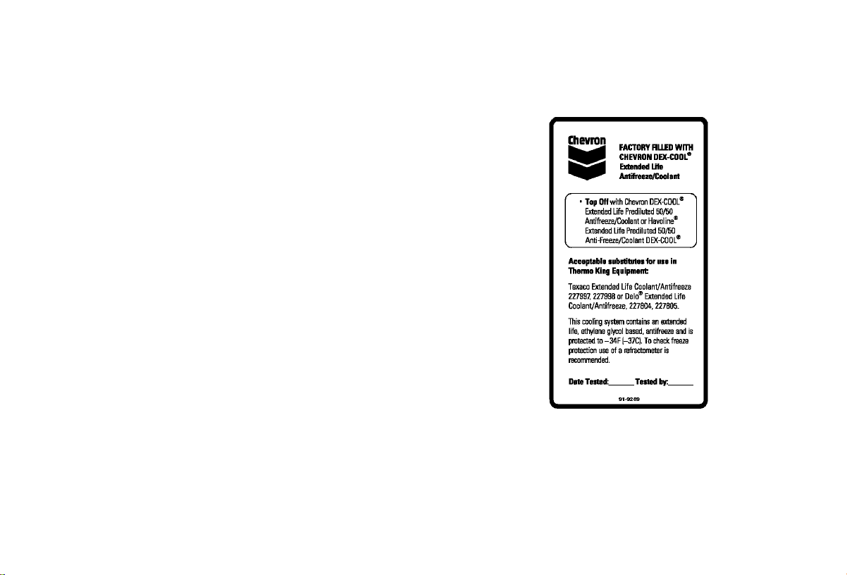
Safety Decals and Locations
Figure 1: ELC (Extended Life Coolant) Nameplate
(On expansion tank)
AJA1947
Other manuals for Precedent S-600
1
This manual suits for next models
1
Table of contents


