Thermo King X214 User manual

Distributed by:
Ingersoll Rand’s Climate Solutions sector delivers energy-effi cient HVACR solutions for
customers globally. Its world class brands include Thermo King, the leader in transport
temperature control and Trane, a provider of energy effi cient heating, ventilating and air
conditioning systems, building and contracting services, parts support and advanced controls
for commercial buildings and homes.
SB-210+
Additional text information
to be placed here
TK 5XXXX-X-PL
TK 6875-8-OM
©1998 Ingersoll Rand Company
Printed in U.S.A.
314 West 90th Street
Minneapolis, MN 55420
Direct (952) 887-2200
Thermo King Corporate
Distributed by:
SB-210+
Additional text information
to be placed here
TK 5XXXX-X-PL
314 West 90th Street
Minneapolis, MN 55420
Direct (952) 887-2200
Thermo King Corporate
SB-210+
Additional text information
to be placed here
TK 5XXXX-X-PL
Distributed by:
314 West 90th Street
Minneapolis, MN 55420
Direct (952) 887-2200
Thermo King Corporate
Distributed by:
X214, X418, X426 &
X430 Compressor
TK 6875-8-OM (Rev. 9, 02/14)
314 West 90th Street
Minneapolis, MN 55420
Direct (952) 887-2200
Thermo King Corporate
Overhaul ManualOverhaul Manual
Overhaul ManualOverhaul ManualOverhaul Manual
Overhaul Manual

X214, X418,
X426 & X430
Compressor
TK 6875-8-OM (Rev. 9, 02/14)
Copyright©1998 Thermo King Corp., Minneapolis, MN, U.S.A. Printed in
U.S.A.
Overhaul Manual

2
Revision History
Rev. 9 – TK 6875-8-OM (Rev. 9, 02/14) Update for Oil Collection Container, Pressurized Seal
Cavity, and Internal Oil Filter.
This manual is published for informational purposes only and the information so provided should
not be considered as all-inclusive or covering all contingencies. If further information is required,
Thermo King Corporation should be consulted.
Sale of product shown in this manual is subject to Thermo King’s terms and conditions
including, but not limited to, the Thermo King Limited Express Warranty. Such terms and
conditions are available upon request. Thermo King’s warranty will not apply to any
equipment which has been “so repaired or altered outside the manufacturer’s plants as,
in the manufacturer’s judgment, to effect its stability.”
No warranties, express or implied, including warranties of fitness for a particular
purpose or merchantability, or warranties arising from course of dealing or usage of
trade, are made regarding the information, recommendations, and descriptions
contained herein. Manufacturer is not responsible and will not be held liable in contract
or in tort (including negligence) for any special, indirect or consequential damages,
including injury or damage caused to vehicles, contents or persons, by reason of the
installation of any Thermo King product or its mechanical failure.

3
Recover Refrigerant
At Thermo King, we recognize the need to preserve the environment
and limit the potential harm to the ozone layer that can result from
allowing refrigerant to escape into the atmosphere.
We strictly adhere to a policy that promotes the recovery and limits
the loss of refrigerant into the atmosphere.
In addition, service personnel must be aware of Federal regulations
concerning the use of refrigerants and the certification of technicians.
For additional information on regulations and technician certification
programs, contact your local Thermo King dealer.

4
CHANGES, COMMENTS and SUGGESTIONS
You are invited to comment on this manual so it can be updated and improved to better meet you
needs. Any corrections, comments or suggestions are welcome. Please complete the following
information:
Manual Form Number _____________________________________________________
Section and Page # _______________________________________________________
Your Name ______________________________________________________________
Company Name __________________________________________________________
Phone Number ___________________________________________________________
Corrections, Comments and Suggestions _____________________________________
________________________________________________________________________
________________________________________________________________________
________________________________________________________________________
________________________________________________________________________
________________________________________________________________________
________________________________________________________________________
________________________________________________________________________
________________________________________________________________________
________________________________________________________________________
Return to:
NORTH AMERICA
THERMO KING CORPORATION
314 West 90th Street
Mail Stop 38
Minneapolis, MN 55420
Attn: Service Department
EUROPEAN SERVED AREA
THERMO KING CORPORATION
Ingersoll Rand Climate Control Technologies
Monivea Road
Mervue, Galway, Ireland
Attn: Service Department

5
Table of Contents
Safety Precautions . . . . . . . . . . . . . . . . . . . . . . . . . . . . . . . . . . . . . . . . . . . . . . . . . . . . . . . . . . . . . . . . . . . . . . . 7
General Practices . . . . . . . . . . . . . . . . . . . . . . . . . . . . . . . . . . . . . . . . . . . . . . . . . . . . . . . . . . . . . . . . . . . . . . . . . 7
Battery Installation and Cable Routing . . . . . . . . . . . . . . . . . . . . . . . . . . . . . . . . . . . . . . . . . . . . . . . . . . . . . . . . . 8
Battery Removal . . . . . . . . . . . . . . . . . . . . . . . . . . . . . . . . . . . . . . . . . . . . . . . . . . . . . . . . . . . . . . . . . . . . . . . . . . 8
Refrigerant Hazards . . . . . . . . . . . . . . . . . . . . . . . . . . . . . . . . . . . . . . . . . . . . . . . . . . . . . . . . . . . . . . . . . . . . . . . 8
Refrigerant Oil Hazards . . . . . . . . . . . . . . . . . . . . . . . . . . . . . . . . . . . . . . . . . . . . . . . . . . . . . . . . . . . . . . . . . . . . 9
Electrical Hazards . . . . . . . . . . . . . . . . . . . . . . . . . . . . . . . . . . . . . . . . . . . . . . . . . . . . . . . . . . . . . . . . . . . . . . . . . 9
High Voltage . . . . . . . . . . . . . . . . . . . . . . . . . . . . . . . . . . . . . . . . . . . . . . . . . . . . . . . . . . . . . . . . . . . . . . . . . . 9
Low Voltage . . . . . . . . . . . . . . . . . . . . . . . . . . . . . . . . . . . . . . . . . . . . . . . . . . . . . . . . . . . . . . . . . . . . . . . . . . 9
First Aid . . . . . . . . . . . . . . . . . . . . . . . . . . . . . . . . . . . . . . . . . . . . . . . . . . . . . . . . . . . . . . . . . . . . . . . . . . . . . . . . 10
First Aid, Refrigerant . . . . . . . . . . . . . . . . . . . . . . . . . . . . . . . . . . . . . . . . . . . . . . . . . . . . . . . . . . . . . . . . . . . 10
First Aid, Refrigerant Oil . . . . . . . . . . . . . . . . . . . . . . . . . . . . . . . . . . . . . . . . . . . . . . . . . . . . . . . . . . . . . . . . 10
First Aid, Engine Coolant . . . . . . . . . . . . . . . . . . . . . . . . . . . . . . . . . . . . . . . . . . . . . . . . . . . . . . . . . . . . . . . 10
First Aid, Electrical Shock . . . . . . . . . . . . . . . . . . . . . . . . . . . . . . . . . . . . . . . . . . . . . . . . . . . . . . . . . . . . . . . 10
Compressor Description . . . . . . . . . . . . . . . . . . . . . . . . . . . . . . . . . . . . . . . . . . . . . . . . . . . . . . . . . . . . . . . . . 11
General Description . . . . . . . . . . . . . . . . . . . . . . . . . . . . . . . . . . . . . . . . . . . . . . . . . . . . . . . . . . . . . . . . . . . . . . 11
Compressor Model Identification . . . . . . . . . . . . . . . . . . . . . . . . . . . . . . . . . . . . . . . . . . . . . . . . . . . . . . . . . . . . 11
Two Cylinder Compressors . . . . . . . . . . . . . . . . . . . . . . . . . . . . . . . . . . . . . . . . . . . . . . . . . . . . . . . . . . . . . 11
Four Cylinder Compressors . . . . . . . . . . . . . . . . . . . . . . . . . . . . . . . . . . . . . . . . . . . . . . . . . . . . . . . . . . . . . 11
Oil Collection Container . . . . . . . . . . . . . . . . . . . . . . . . . . . . . . . . . . . . . . . . . . . . . . . . . . . . . . . . . . . . . . . . . . . 14
Specifications . . . . . . . . . . . . . . . . . . . . . . . . . . . . . . . . . . . . . . . . . . . . . . . . . . . . . . . . . . . . . . . . . . . . . . . . . . 22
Torque Values . . . . . . . . . . . . . . . . . . . . . . . . . . . . . . . . . . . . . . . . . . . . . . . . . . . . . . . . . . . . . . . . . . . . . . . 24
Special Tools . . . . . . . . . . . . . . . . . . . . . . . . . . . . . . . . . . . . . . . . . . . . . . . . . . . . . . . . . . . . . . . . . . . . . . . . 25
General Compressor Repair Techniques . . . . . . . . . . . . . . . . . . . . . . . . . . . . . . . . . . . . . . . . . . . . . . . . . . . . 26
Dirt and Moisture can Easily Ruin Compressors! . . . . . . . . . . . . . . . . . . . . . . . . . . . . . . . . . . . . . . . . . . . . . . . . 26
Compressor Oil Indications . . . . . . . . . . . . . . . . . . . . . . . . . . . . . . . . . . . . . . . . . . . . . . . . . . . . . . . . . . . . . . . . . 26
Compressor Oil Color Code . . . . . . . . . . . . . . . . . . . . . . . . . . . . . . . . . . . . . . . . . . . . . . . . . . . . . . . . . . . . . . . . 26
Disassembly and Reassembly . . . . . . . . . . . . . . . . . . . . . . . . . . . . . . . . . . . . . . . . . . . . . . . . . . . . . . . . . . . . . 28
Disassembly Sequence . . . . . . . . . . . . . . . . . . . . . . . . . . . . . . . . . . . . . . . . . . . . . . . . . . . . . . . . . . . . . . . . . . . 28
Reassembly Sequence . . . . . . . . . . . . . . . . . . . . . . . . . . . . . . . . . . . . . . . . . . . . . . . . . . . . . . . . . . . . . . . . . . . . 28
Fastener Torque Procedure . . . . . . . . . . . . . . . . . . . . . . . . . . . . . . . . . . . . . . . . . . . . . . . . . . . . . . . . . . . . . . . . 28
Cleaning Components . . . . . . . . . . . . . . . . . . . . . . . . . . . . . . . . . . . . . . . . . . . . . . . . . . . . . . . . . . . . . . . . . . . . 28
Drive Coupling . . . . . . . . . . . . . . . . . . . . . . . . . . . . . . . . . . . . . . . . . . . . . . . . . . . . . . . . . . . . . . . . . . . . . . . . . . 28
Removal . . . . . . . . . . . . . . . . . . . . . . . . . . . . . . . . . . . . . . . . . . . . . . . . . . . . . . . . . . . . . . . . . . . . . . . . . . . . 28
Installation . . . . . . . . . . . . . . . . . . . . . . . . . . . . . . . . . . . . . . . . . . . . . . . . . . . . . . . . . . . . . . . . . . . . . . . . . . 29
Cylinder Head . . . . . . . . . . . . . . . . . . . . . . . . . . . . . . . . . . . . . . . . . . . . . . . . . . . . . . . . . . . . . . . . . . . . . . . . . . . 32
Removal . . . . . . . . . . . . . . . . . . . . . . . . . . . . . . . . . . . . . . . . . . . . . . . . . . . . . . . . . . . . . . . . . . . . . . . . . . . . 32
Repair . . . . . . . . . . . . . . . . . . . . . . . . . . . . . . . . . . . . . . . . . . . . . . . . . . . . . . . . . . . . . . . . . . . . . . . . . . . . . . 32
Installation . . . . . . . . . . . . . . . . . . . . . . . . . . . . . . . . . . . . . . . . . . . . . . . . . . . . . . . . . . . . . . . . . . . . . . . . . . 32
Discharge Valve Plates . . . . . . . . . . . . . . . . . . . . . . . . . . . . . . . . . . . . . . . . . . . . . . . . . . . . . . . . . . . . . . . . . . . . 33
Removal . . . . . . . . . . . . . . . . . . . . . . . . . . . . . . . . . . . . . . . . . . . . . . . . . . . . . . . . . . . . . . . . . . . . . . . . . . . . 33
Repair . . . . . . . . . . . . . . . . . . . . . . . . . . . . . . . . . . . . . . . . . . . . . . . . . . . . . . . . . . . . . . . . . . . . . . . . . . . . . . 34
Installation . . . . . . . . . . . . . . . . . . . . . . . . . . . . . . . . . . . . . . . . . . . . . . . . . . . . . . . . . . . . . . . . . . . . . . . . . . 34
Two-piece Compressor Seal Plate and Mounting Flange Assembly . . . . . . . . . . . . . . . . . . . . . . . . . . . . . . . . . 35
Seal Plate Assembly . . . . . . . . . . . . . . . . . . . . . . . . . . . . . . . . . . . . . . . . . . . . . . . . . . . . . . . . . . . . . . . . . . . . . . 35
Removal . . . . . . . . . . . . . . . . . . . . . . . . . . . . . . . . . . . . . . . . . . . . . . . . . . . . . . . . . . . . . . . . . . . . . . . . . . . . 35
Repair . . . . . . . . . . . . . . . . . . . . . . . . . . . . . . . . . . . . . . . . . . . . . . . . . . . . . . . . . . . . . . . . . . . . . . . . . . . . . . 37
Installation of Spring Loaded Neoprene Bellows Type Seal . . . . . . . . . . . . . . . . . . . . . . . . . . . . . . . . . . . . . 37
Installation of Metal Bellows Seal With Set Screws . . . . . . . . . . . . . . . . . . . . . . . . . . . . . . . . . . . . . . . . . . . 39
Installation of Metal Bellows Seal With Drive Tangs . . . . . . . . . . . . . . . . . . . . . . . . . . . . . . . . . . . . . . . . . . 41
Installation of Metal Bellows Seal With Hex Drive . . . . . . . . . . . . . . . . . . . . . . . . . . . . . . . . . . . . . . . . . . . . 42
Oil Sump and Oil Pickup Screen . . . . . . . . . . . . . . . . . . . . . . . . . . . . . . . . . . . . . . . . . . . . . . . . . . . . . . . . . . . . . 44
Removal . . . . . . . . . . . . . . . . . . . . . . . . . . . . . . . . . . . . . . . . . . . . . . . . . . . . . . . . . . . . . . . . . . . . . . . . . . . . 44
Repair . . . . . . . . . . . . . . . . . . . . . . . . . . . . . . . . . . . . . . . . . . . . . . . . . . . . . . . . . . . . . . . . . . . . . . . . . . . . . . 44
Installation . . . . . . . . . . . . . . . . . . . . . . . . . . . . . . . . . . . . . . . . . . . . . . . . . . . . . . . . . . . . . . . . . . . . . . . . . . 45

Table of Contents
6
Internal Oil Filter . . . . . . . . . . . . . . . . . . . . . . . . . . . . . . . . . . . . . . . . . . . . . . . . . . . . . . . . . . . . . . . . . . . . . . . . .46
Removal . . . . . . . . . . . . . . . . . . . . . . . . . . . . . . . . . . . . . . . . . . . . . . . . . . . . . . . . . . . . . . . . . . . . . . . . . . . .46
Installation . . . . . . . . . . . . . . . . . . . . . . . . . . . . . . . . . . . . . . . . . . . . . . . . . . . . . . . . . . . . . . . . . . . . . . . . . . .46
Oil Pump . . . . . . . . . . . . . . . . . . . . . . . . . . . . . . . . . . . . . . . . . . . . . . . . . . . . . . . . . . . . . . . . . . . . . . . . . . . . . . .47
Removal . . . . . . . . . . . . . . . . . . . . . . . . . . . . . . . . . . . . . . . . . . . . . . . . . . . . . . . . . . . . . . . . . . . . . . . . . . . .47
Repair . . . . . . . . . . . . . . . . . . . . . . . . . . . . . . . . . . . . . . . . . . . . . . . . . . . . . . . . . . . . . . . . . . . . . . . . . . . . . .48
Pre-Lubrication of Oil Pump Parts . . . . . . . . . . . . . . . . . . . . . . . . . . . . . . . . . . . . . . . . . . . . . . . . . . . . . . . .49
Installation . . . . . . . . . . . . . . . . . . . . . . . . . . . . . . . . . . . . . . . . . . . . . . . . . . . . . . . . . . . . . . . . . . . . . . . . . . .49
Connecting Rod, Piston and Sleeve . . . . . . . . . . . . . . . . . . . . . . . . . . . . . . . . . . . . . . . . . . . . . . . . . . . . . . . . . .51
Removal . . . . . . . . . . . . . . . . . . . . . . . . . . . . . . . . . . . . . . . . . . . . . . . . . . . . . . . . . . . . . . . . . . . . . . . . . . . .51
Repair . . . . . . . . . . . . . . . . . . . . . . . . . . . . . . . . . . . . . . . . . . . . . . . . . . . . . . . . . . . . . . . . . . . . . . . . . . . . . .51
Assembly . . . . . . . . . . . . . . . . . . . . . . . . . . . . . . . . . . . . . . . . . . . . . . . . . . . . . . . . . . . . . . . . . . . . . . . . . . .53
Crankshaft . . . . . . . . . . . . . . . . . . . . . . . . . . . . . . . . . . . . . . . . . . . . . . . . . . . . . . . . . . . . . . . . . . . . . . . . . . . . . .54
Removal . . . . . . . . . . . . . . . . . . . . . . . . . . . . . . . . . . . . . . . . . . . . . . . . . . . . . . . . . . . . . . . . . . . . . . . . . . . .54
Repair . . . . . . . . . . . . . . . . . . . . . . . . . . . . . . . . . . . . . . . . . . . . . . . . . . . . . . . . . . . . . . . . . . . . . . . . . . . . . .56
Installation . . . . . . . . . . . . . . . . . . . . . . . . . . . . . . . . . . . . . . . . . . . . . . . . . . . . . . . . . . . . . . . . . . . . . . . . . . .57
Compressor Crankshaft Precautions . . . . . . . . . . . . . . . . . . . . . . . . . . . . . . . . . . . . . . . . . . . . . . . . . . . . . .59
Removal and Installing Crankshaft Counterweights . . . . . . . . . . . . . . . . . . . . . . . . . . . . . . . . . . . . . . . . . . .60
Compressor Body Repair . . . . . . . . . . . . . . . . . . . . . . . . . . . . . . . . . . . . . . . . . . . . . . . . . . . . . . . . . . . . . . . . . .61
Removal . . . . . . . . . . . . . . . . . . . . . . . . . . . . . . . . . . . . . . . . . . . . . . . . . . . . . . . . . . . . . . . . . . . . . . . . . . . .61
Inspection . . . . . . . . . . . . . . . . . . . . . . . . . . . . . . . . . . . . . . . . . . . . . . . . . . . . . . . . . . . . . . . . . . . . . . . . . . .62
Check Valve Installation . . . . . . . . . . . . . . . . . . . . . . . . . . . . . . . . . . . . . . . . . . . . . . . . . . . . . . . . . . . . . . . .62
Unloader Head . . . . . . . . . . . . . . . . . . . . . . . . . . . . . . . . . . . . . . . . . . . . . . . . . . . . . . . . . . . . . . . . . . . . . . . . . .63
Operation . . . . . . . . . . . . . . . . . . . . . . . . . . . . . . . . . . . . . . . . . . . . . . . . . . . . . . . . . . . . . . . . . . . . . . . . . . . . . . .63
Check Out . . . . . . . . . . . . . . . . . . . . . . . . . . . . . . . . . . . . . . . . . . . . . . . . . . . . . . . . . . . . . . . . . . . . . . . . . . . . . .63
Disassembly . . . . . . . . . . . . . . . . . . . . . . . . . . . . . . . . . . . . . . . . . . . . . . . . . . . . . . . . . . . . . . . . . . . . . . . . . . . .64
Repair . . . . . . . . . . . . . . . . . . . . . . . . . . . . . . . . . . . . . . . . . . . . . . . . . . . . . . . . . . . . . . . . . . . . . . . . . . . . . . . . .64
Leak Testing, Storage, and Startup . . . . . . . . . . . . . . . . . . . . . . . . . . . . . . . . . . . . . . . . . . . . . . . . . . . . . . . . .65
Leak Testing . . . . . . . . . . . . . . . . . . . . . . . . . . . . . . . . . . . . . . . . . . . . . . . . . . . . . . . . . . . . . . . . . . . . . . . . . . . .65
Storage . . . . . . . . . . . . . . . . . . . . . . . . . . . . . . . . . . . . . . . . . . . . . . . . . . . . . . . . . . . . . . . . . . . . . . . . . . . . . . . .65
Startup . . . . . . . . . . . . . . . . . . . . . . . . . . . . . . . . . . . . . . . . . . . . . . . . . . . . . . . . . . . . . . . . . . . . . . . . . . . . . . . . .65
Compressor History . . . . . . . . . . . . . . . . . . . . . . . . . . . . . . . . . . . . . . . . . . . . . . . . . . . . . . . . . . . . . . . . . . . . .67
Compressor History . . . . . . . . . . . . . . . . . . . . . . . . . . . . . . . . . . . . . . . . . . . . . . . . . . . . . . . . . . . . . . . . . . . . . . .67
Released . . . . . . . . . . . . . . . . . . . . . . . . . . . . . . . . . . . . . . . . . . . . . . . . . . . . . . . . . . . . . . . . . . . . . . . . . . . .67
Two-piece Compressor Seal Plate and Mounting Flange Assembly . . . . . . . . . . . . . . . . . . . . . . . . . . . . . .67
Metal Bellows Crankshaft Seal with Set Screws . . . . . . . . . . . . . . . . . . . . . . . . . . . . . . . . . . . . . . . . . . . . . .67
Polyol Ester (POE) Compressor Oil for HFC Refrigerants . . . . . . . . . . . . . . . . . . . . . . . . . . . . . . . . . . . . . .67
Groove Top Pistons . . . . . . . . . . . . . . . . . . . . . . . . . . . . . . . . . . . . . . . . . . . . . . . . . . . . . . . . . . . . . . . . . . .67
Teflon Seal Type Drive End Ball Bearing . . . . . . . . . . . . . . . . . . . . . . . . . . . . . . . . . . . . . . . . . . . . . . . . . . .67
New Coupling Mounting Washer . . . . . . . . . . . . . . . . . . . . . . . . . . . . . . . . . . . . . . . . . . . . . . . . . . . . . . . . .67
Large Shaft Compressor . . . . . . . . . . . . . . . . . . . . . . . . . . . . . . . . . . . . . . . . . . . . . . . . . . . . . . . . . . . . . . . .67
Metal Bellows Crankshaft Seal with Drive Tangs . . . . . . . . . . . . . . . . . . . . . . . . . . . . . . . . . . . . . . . . . . . . .67
8 Pin Coupling and Clutch . . . . . . . . . . . . . . . . . . . . . . . . . . . . . . . . . . . . . . . . . . . . . . . . . . . . . . . . . . . . . .67
Fins Eliminated from Crankcase . . . . . . . . . . . . . . . . . . . . . . . . . . . . . . . . . . . . . . . . . . . . . . . . . . . . . . . . . .67
Seven Quart Oil Sump on Four Cylinder Compressors . . . . . . . . . . . . . . . . . . . . . . . . . . . . . . . . . . . . . . . .67
Deep Oil Sump on Two Cylinder Compressors . . . . . . . . . . . . . . . . . . . . . . . . . . . . . . . . . . . . . . . . . . . . . .67
Increase Bronze Bearing Bore Diameter in Oil Pump Housing . . . . . . . . . . . . . . . . . . . . . . . . . . . . . . . . . . .68
Improve Heat Treating on Oil Pump Shaft . . . . . . . . . . . . . . . . . . . . . . . . . . . . . . . . . . . . . . . . . . . . . . . . . .68
HPCO Switch with Straight Threads . . . . . . . . . . . . . . . . . . . . . . . . . . . . . . . . . . . . . . . . . . . . . . . . . . . . . . .68
C5 Crankshaft Drive End Bearing and Cast Iron Oil Pump Housing . . . . . . . . . . . . . . . . . . . . . . . . . . . . . .68
Oil Collection Container . . . . . . . . . . . . . . . . . . . . . . . . . . . . . . . . . . . . . . . . . . . . . . . . . . . . . . . . . . . . . . . .68
Check Valve in Oil Collection Container . . . . . . . . . . . . . . . . . . . . . . . . . . . . . . . . . . . . . . . . . . . . . . . . . . . .68
Pressurized Seal Cavity . . . . . . . . . . . . . . . . . . . . . . . . . . . . . . . . . . . . . . . . . . . . . . . . . . . . . . . . . . . . . . . .68
Internal Oil Filter . . . . . . . . . . . . . . . . . . . . . . . . . . . . . . . . . . . . . . . . . . . . . . . . . . . . . . . . . . . . . . . . . . . . . .68
Index . . . . . . . . . . . . . . . . . . . . . . . . . . . . . . . . . . . . . . . . . . . . . . . . . . . . . . . . . . . . . . . . . . . . . . . . . . . . . . . . . .69

7
Safety Precautions
Thermo King recommends that all service be
performed by a Thermo King dealer. However,
you should be aware of several general safety
practices:
The symbol appears next to a point that is
particularly important
General Practices
DANGER: Denotes the possibility of
serious injury or death.
WARNING: Denotes the possibility of
serious equipment damage or serious
personal injury.
CAUTION: Denotes the possibility of
minor to severe equipment damage or
personal injury.
DANGER: Do not operate the compressor
with the discharge service valve closed.
This condition increases internal pressure,
which can cause an explosion.
DANGER: Never apply heat to a sealed
refrigeration system or container. Heat
increases internal pressure, which might
cause an explosion.
DANGER: Refrigerant in the presence of
an open flame, spark or electrical short
produces toxic gases that are severe
respiratory irritants.
DANGER: Keep your hands, clothing and
tools clear of fans when working on a unit
that is running. Loose clothing might
entangle moving pulleys or belts, causing
serious injury or possible death.
DANGER: Do not inhale refrigerant. Use
caution when working with refrigerant or
a refrigeration system in any confined
area with a limited air supply, such as a
cargo area or garage. Refrigerant
displaces air and can cause oxygen
depletion, resulting in suffocation and
possible death.
DANGER: Avoid engine operation in
confined spaces and areas or
circumstances where fumes from the
engine could become trapped and cause
serious injury or death.
WARNING: Make sure your gauge
manifold hoses are in good condition
before using them. Never let them come in
contact with moving belts, fans, pulleys or
hot surfaces. Defective gauge equipment
can damage components or cause serious
injury.
WARNING: Always wear goggles or safety
glasses when working on a unit.
Refrigerant liquid, oil and battery acid can
permanently damage your eyes. See “First
Aid” on page 10.
WARNING: Use extreme caution when
drilling holes in a unit. Holes might
weaken structural components. Holes
drilled into electrical wiring can cause a
fire or explosion.
WARNING: Exposed coil fins can cause
lacerations. Service work on the
evaporator or condenser coils is best left to
a certified Thermo King technician.
WARNING: Do not apply heat to a closed
cooling system. Before applying heat to a
cooling system, drain it. Then flush it with
water and drain the water. Antifreeze
contains water and ethylene glycol. The
ethylene glycol is flammable and can
ignite if the antifreeze is heated enough to
boil off the water.
WARNING: Be careful when using
ladders or scaffolding to install or service
a unit. Observe the manufacture’s safety
labels and warnings.
CAUTION: Make sure all mounting bolts
are tight and are the correct length for
their applications. Improper torque and
incorrect bolt lengths can damage
equipment.

Safety Precautions
8
NOTE: In the USA, EPA Section 608
Certification is required to work on refrigeration
systems.
Battery Installation and Cable
Routing
Battery Removal
This order is important because the frame is
grounded to the negative battery terminal. If the
negative terminal is still connected, a complete
circuit exists from the positive terminal of the
battery to the frame. Metal objects contacting the
positive side and the frame simultaneously will
cause sparks or arcing. If there are sufficient
hydrogen gases emitted from the battery, an
explosion might occur, causing equipment
damage, serious injury, even death.
Refrigerant Hazards
WARNING: Improperly installed battery
could result in a fire or explosion! A
Thermo King approved battery must be
installed and properly secured to the
battery tray.
WARNING: Improperly installed battery
cables could result in fire or explosion!
Battery cables must be installed, routed
and secured properly to prevent them from
rubbing, chaffing or making contact with
hot, sharp or rotating components.
WARNING: Do not attach fuel lines or
any additional wiring harnesses to the
battery cables as this could cause an
electrical fire!
CAUTION: Do not connect other
manufacturer’s equipment or accessories
to the Thermo King unit. This could result
in severe damage to equipment and void
the warranty!
CAUTION: Set all unit electrical controls
to the OFF position before connecting
battery cables to the battery to prevent unit
from starting unexpectedly and causing
personal injury.
CAUTION: Always wear protective
clothing, gloves and eye wear when
handling and installing batteries. Battery
acid can cause serious burns when
exposed to eyes or skin. If battery acid
contacts skin or clothing, wash
immediately with soap and water. If acid
enters your eye, immediately flood it with
running cold water for at least twenty
minutes and get medical attention
immediately.
CAUTION: Always cover battery
terminals to prevent them from making
contact with metal components during
battery installation. Battery terminals
grounding against metal could cause the
battery to explode.
DANGER: Disconnect the negative
battery terminal (-) first when removing a
battery. Connect the positive terminal (+)
first when installing a battery.
DANGER: Do not use a Halide torch.
When a flame comes in contact with
refrigerant, toxic gases are produced.
These gases can cause suffocation, even
death.
DANGER: Store refrigerant in proper
containers, out of direct sunlight and away
from intense heat. Heat increases pressure
inside storage containers, which can cause
them to burst.
DANGER: Do not use oxygen (O2 ) or
compressed air for leak testing. Oxygen
mixed with refrigerant is combustible.
WARNING: Wear butyl lined gloves when
handling refrigerant to help prevent
frostbite.

Safety Precautions
9
Refrigerant Oil Hazards
Electrical Hazards
High Voltage
Low Voltage
CAUTION: Refrigerant in a liquid state
evaporates rapidly when exposed to the
atmosphere, freezing anything it contacts.
Be careful when handling refrigerant to
protect your skin from frostbite.
CAUTION: When being transferred,
refrigerant must be in liquid state to avoid
possible equipment damage.
CAUTION: When transferring
refrigerant, use a process that prevents or
greatly restricts refrigerant from escaping
into the atmosphere. Refrigerant damages
the earth’s upper ozone layer.
WARNING: Protect your eyes from
contact with refrigerant oil. The oil can
cause serious eye injuries. Avoid
prolonged or repeated contact with
refrigerant oil. To prevent irritation, wash
your hands and clothing thoroughly after
handling the oil.
CAUTION: Use the correct oil in Thermo
King systems to avoid damaging
equipment and invalidating its warranty.
CAUTION: Do not mix refrigerant oils
because that can cause system damage.
CAUTION: Use dedicated equipment to
prevent contaminating systems with the
wrong type of oil.
CAUTION: Store refrigerant oil in an
approved sealed container to avoid
moisture contamination.
CAUTION: Do not expose the refrigerant
oil to the air any longer than necessary.
The oil will absorb moisture, which results
in much longer evacuation times and
possible system contamination.
CAUTION: Wipe up spills immediately.
Refrigerant oil can damage paints and
rubber materials.
DANGER: Lethal amounts of voltage are
present in some electrical circuits. Use
extreme care when working on an
operating refrigeration unit.
WARNING: Do not make rapid moves
when working on high voltage circuits in
refrigeration units. Do not grab for falling
tools because you might accidentally touch
a high voltage source.
WARNING: Use tools with well insulated
handles. Never hold uninsulated metal
tools near exposed, energized conductors.
WARNING: Treat all wires and
connections as if they were high voltage
until a meter and wiring diagram indicate
otherwise.
WARNING: Never work alone on high
voltage circuits in the refrigeration unit.
Another person should be nearby to shut
off the unit and provide aid in the event of
an accident.
WARNING: Safety glasses, rubber-
insulated gloves and cable cutters should
be near your work area, in the event of an
electrical accident.
WARNING: Use caution when working
with electrical circuits that contain
capacitors. Some capacitors hold a
significant charge that might cause burns
or shocks if accidentally discharged. Make
sure capacitors are discharged before
working on electrical circuits.
WARNING: Control circuits used in
refrigeration units are low voltage (12 to
24 volts dc). This voltage is not dangerous,
but the large amount of amperage
available from the alternator can cause
severe burns if accidentally shorted to
ground with metal objects, such as tools.

Safety Precautions
10
First Aid
First Aid, Refrigerant
In the event of frostbite, protect the frozen area
from further injury, warm the area rapidly and
maintain respiration.
EYES : For contact with liquid, immediately flush
eyes with large amounts of water. CALL A
PHYSICIAN.
SKIN: Flush area with large amounts of warm
water. Do not apply heat. Remove contaminated
clothing and shoes. Wrap burns with dry, sterile,
bulky dressing to protect from infection. CALL A
PHYSICIAN. Wash contaminated clothing before
reuse.
INHALATION: Move victim to fresh air and use
CPR (cardio pulmonary resuscitation) or
mouth-to-mouth resuscitation to restore breathing,
if necessary. Stay with victim until emergency
personnel arrive.
First Aid, Refrigerant Oil
EYES : Immediately flush with water for at least
15 minutes. CALL A PHYSICIAN. Wash skin
with soap and water.
INGESTION: Do not induce vomiting.
Immediately contact local poison control center or
physician.
First Aid, Engine Coolant
EYES : Immediately flush with water for at least
15 minutes. CALL A PHYSICIAN. Wash skin
with soap and water.
INGESTION: Do not induce vomiting.
Immediately contact local poison control center or
physician.
First Aid, Electrical Shock
Take IMMEDIATE action after a person has
received an electrical shock. Get quick medical
assistance, if possible.
The source of the shock must be quickly stopped,
by either shutting off the power or removing the
victim. If the power cannot be shut off, the wire
should be cut with an non-conductive tool, such as
a wood-handle axe or thickly insulated cable
cutters. Rescuers should wear insulated gloves
and safety glasses, and avoid looking at wires
being cut. The ensuing flash can cause burns and
blindness.
If the victim must be removed from a live circuit,
pull the victim away with a non-conductive
material. Use wood, rope, a belt or coat to pull or
push the victim away from the current. DO NOT
TOUCH the victim. You will receive a shock from
current flowing through the victim’s body. After
separating the victim from power source,
immediately check for signs of a pulse and
respiration. If no pulse is present, start CPR
(cardio pulmonary resuscitation). If a pulse is
present, respiration might be restored by using
mouth-to-mouth resuscitation. Call for emergency
medical assistance.
WARNING: Do not wear jewelry, watches
or rings because they increase the risk of
shorting out electrical circuits and
damaging equipment or causing severe
burns.

11
Compressor Description
General Description
The most significant part of the refrigeration
system is the compressor. Its function is to pump
low pressure gas out of the evaporator so that a
rapid and continuous boiling action is maintained
in the evaporator coil. The low pressure gas is
compressed and forced into the condenser coil
where it is cooled by air passing through the coil.
The high pressure and reduced temperature causes
it to liquefy (condense).
The compressors covered by this manual are
reciprocating piston type pumps, constructed
mainly of cast aluminum. The aluminum alloy
pistons and cast iron sleeves are machined to close
tolerances to that no rings are needed to seal the
piston to the cylinder wall. The compressor is
equipped with a high nickel alloy ductile iron
crankshaft. To prevent leakage around the
crankshaft, the compressor is fitted with a rotary
type refrigeration seal.
Pressurized lubrication is provided to the
connecting rods and bearings by a gerotor oil
pump in the compressor body. The oil level in the
compressor can be inspected through the oil level
sight glass in the body. Since the refrigeration
system is sealed, it should be necessary to add oil
only if there has been a large refrigeration leak in
the system, or if a major item in the refrigeration
system, such as an evaporator coil or a condenser
coil has been replaced.
A spring loaded discharge valve and spring loaded
valve cage provide pressure relief if liquid
refrigerant enters the compressor. The entire cage
lifts and prevents breaking or deforming of the
valves.
When any repairs or replacements are to be made
on the compressor, it is very important that the
parts used are clean and not nicked or scratched.
During disassembly, parts should be cleaned and
inspected; and if they are to be used in
reassembly, they should be wrapped in a clean
cloth to prevent marring the surfaces. Oil all parts
with compressor oil during assembly, and be sure
they are installed in the same position they were
in before disassembly.
NOTE: When replacement parts are required,
we recommend using only Factory Approved
Thermo King Replacement Parts. Only Genuine
Thermo King Replacement Parts deliver the
reliability,productivity, quality, and performance
you’ve come to expect from Thermo King.
NOTE: Most of the overhaul procedures for the
compressors covered in this manual are the
same. Photographs of an X426 compressor are
used in this manual as examples. Other
illustrations are provided in cases where the
photograph is not applicable.
Compressor Model
Identification
There are a number of compressor models. The
following information is provided to help identify
the different compressor models. Refer to the
appropriate Parts Manual to order the correct
parts.
Two Cylinder Compressors
The one basic model of the two cylinder
compressor is the X214. There are some minor
variations such as fittings and oil sumps, but
otherwise all X214 compressors are basically the
same.
Four Cylinder Compressors
There are four major differences in the four
cylinder compressors:
• The crankshaft drive shaft diameter is either
1.0 in. (small shaft), or 1.187 in. (large shaft).
• The crankshaft drive end bearing is either a C3
bearing, or a C5 bearing.
• A pressurized seal cavity was phased into use
on large shaft compressors starting in the first
quarter of 2014.
• An internal oil filter were phased into use on
large and small shaft compressors in truck and
trailer units that typically use compressors
with an external oil filter starting in the first
quarter of 2014.
Compressor Description
12
These differences combine to make five basic
types.
• The small shaft compressor with a C3
crankshaft drive end bearing. This type
includes the X418, X426, and X430.
• The small shaft compressor with a C5
crankshaft drive end bearing. This type
includes the X418C5, X426C5, and X430C5.
NOTE: Some small shaft compressors with a
C5 crankshaft drive end bearing used in
truck units also have an internal oil filter.
• The large shaft compressor with a C3
crankshaft drive end bearing. This type
includes the X426LS, and X430LS.
• The large shaft compressor with a C5
crankshaft drive end bearing. This type
includes the X426LSC5, and X430LSC5.
• The large shaft compressor with a C5
crankshaft drive end bearing, a pressurized
seal cavity, and an internal oil filter. This type
also includes the X426P, and X430P.
The following table shows the four cylinder
compressor models according to the shaft size and
the crankshaft drive end bearing used.
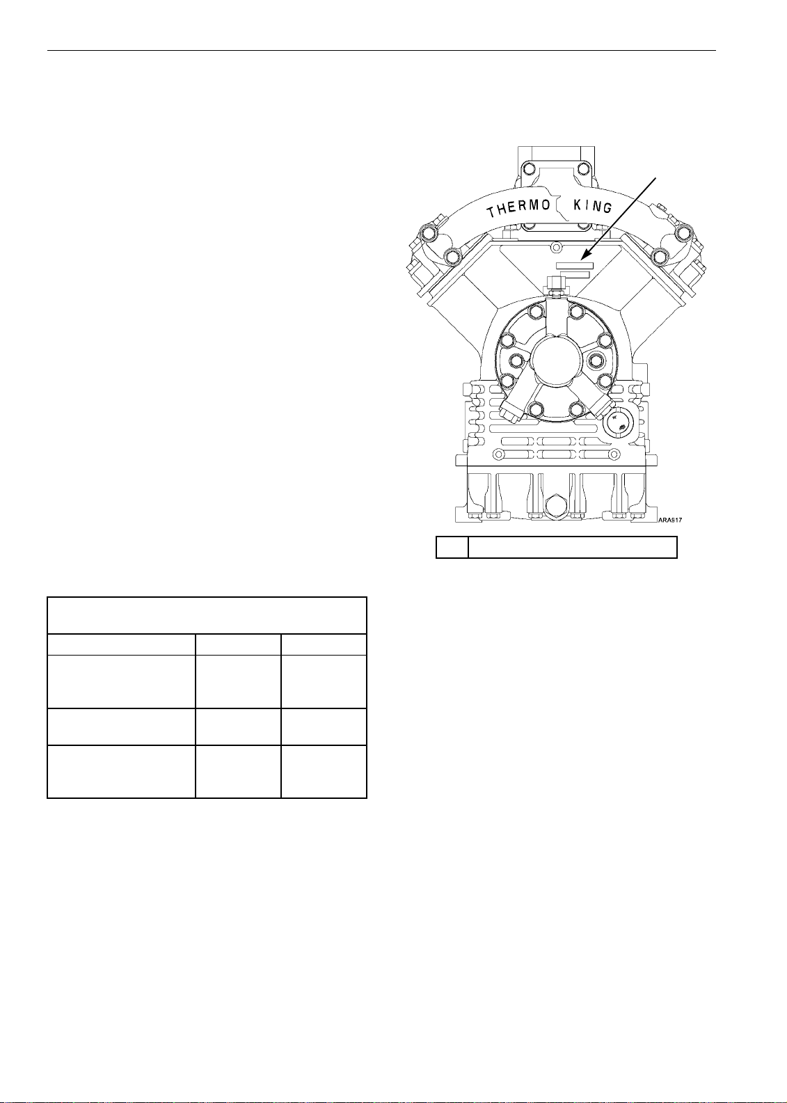
The compressor model is marked on the four
cylinder compressor body as shown below in
Figure 1.
Compressor Model by Shaft Size
and Bearing Type
C3 Bearing C5 Bearing
Small Shaft X418
X426
X430
X418C5
X426C5
X430C5
Large Shaft X426LS
X430LS X426LSC5
X430LSC5
Large Shaft with
Pressurized Seal
Cavity
X426P
X430P
1. Compressor Model Marked Here
Figure 1: Typical Compressor Model Location
1
Compressor Description
13
Compressors that have a C5 crankshaft drive end
bearing also have a cast iron oil pump housing,
which is painted black. Therefore, a compressor
with a C5 bearing can be identified by the black
oil pump housing as shown in Figure 2.
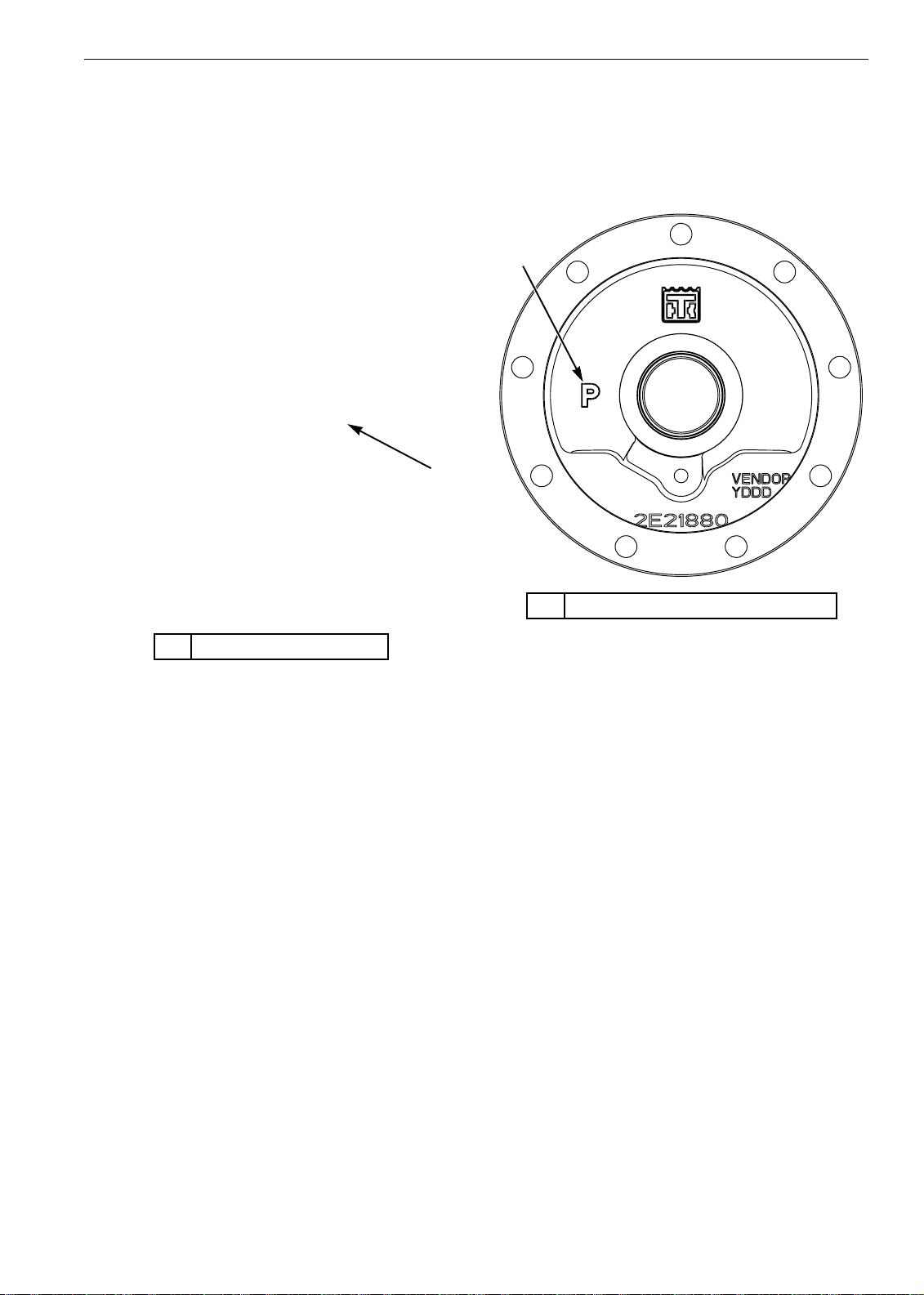
Compressors that have a pressurized seal cavity
have a “P” on the seal cover. Therefore, a
compressor with a pressurized seal cavity can be
identified by the “P” on the seal cover as shown in
Figure 3.
1. Black Oil Pump Housing
Figure 2: Compressor with C5 Bearing
1
1. “P” Indicates Pressurized Seal Cavity
Figure 3: Seal Cover for Compressor with
Pressurized Seal Cavity
ARA2163
1

Compressor Description
14
Oil Collection Container
The oil collection container was added to trailer
units starting in the first quarter of 2010. The oil
collection container collects the compressor shaft
seal seepage to keep the unit clean. This seepage
is normal and is necessary for shaft seal durability.
The oil collection container is mounted on the
body of the compressor. A tube connects the oil
collection container to the compressor shaft seal
cover. The oil that seeps from the seal will travel
through the tube and collect in the container.
Empty the container once per year during oil
changes, or during annual services. The container
has a drain spout with a cap. Remove cap and
drain the oil into a cup (not provided) and discard
the oil properly. Retighten the cap snugly by hand.
NOTE: The oil collection bottle is not used in
Europe.
The check valve was added in November 2012 to
improve the shaft seal reliability by ensuring oil
stays on the shaft seal when the suction pressure is
in a vacuum. It is made of silicone rubber, a
material that can be damaged easily. The check
valve is located on the end of the tube inside the
container. It is a very tight fit between the check
valve and the grommet in the oil collection
container.
NOTE: The check valve is no longer required on
Pressurized Seal Cavity Compressors.
If maintenance in the area requires removal of the
oil collection container or the tube, caution should
be observed to prevent damage to the check valve.
Although the check valve was glued to the tube at
production, pulling the check valve back through
the grommet may cause the Valve to fall off or be
damaged.
Several options are available:
1. If possible, disconnect the tube at the seal
cover drain barb and leave the tube in the oil
collection container.
2. The grommet can be pried off the bottle with
the tube still inserted, allowing the tube and
check valve to be easily removed from the
container.
1. Tube to Compressor Shaft Seal Cover
2. Compressor Mounting Flange
(Sectioned to Show Detail)
3. Oil Collection Container
4. Cap (Remove to Drain Oil)
Figure 4: Oil Collection Container Components
1
3
4
2
1. Seal Cover Drain Barb
2. Tube from Seal Cover to Oil Collection
Container
3. Grommet
4. Check Valve (Starting in November 2012)
5. Oil Collection Container
Figure 5: Oil Collection Container Showing Check
Valve
1
5
3
4
2

Compressor Description
15
3. If option 1 or 2 are not feasible and it is
necessary to pull the check valve back through
the grommet, gently twist as pulling back.
If the check valve does come off the tube, install a
new check valve from stock.

Compressor Description
16
Figure 6: Two Cylinder Compressor
ARC018

Compressor Description
17
1. Compressor Body 45. Oil Pump Shaft Key
2. Cylinder Head Gasket 46. Oil Pump Housing
3. Cylinder Head 47. Oil Pump Assembly
4. O-ring 48. Oil Pump Cover O-ring
5. Sealing Washer 49. O-ring
6. Bolt (3/8-16 x 2) 50. Oil Pump Cover Plate
7. Bolt (3/8-16 x 2-5/8) 51. Bolt (5/16-18 x 1-1/8)
8. Discharge Valve Assembly Bolt (3/8-16 x 2-1/4)
12. Stud 52. Flatwasher
20. Valve Plate O-ring 53. Oil Pressure Regulator Assembly
21. Cylinder Sleeve 54. Regulator O-ring
22. Adapter Gasket 55. Plug
23. Suction Port Screen 56. Plug O-ring
25. Piston Assembly 57. Oil Line Fitting or Valve
26. Piston Pin 58. Oil Sump
27. Piston Pin Retaining Ring 59. Oil Sump Gasket
31. Connecting Rod Assembly 60. Bolt
32. Connecting Rod Bolt 61. Bolt
33. Connecting Rod Nut 62. Copper Washer
34. Bearing Set (Standard) 63. Oil Sump Screen
Bearing Set (0.005) 64. Oil Pickup O-ring
Bearing Set (0.010) 65. Bolt
Bearing Set (0.020) 66. Lockwasher
Bearing Set (0.030) 67. Flatwasher
35. Pump Shaft O-ring 68. Check Valve Assembly
36. Crankshaft Pump End Bearing 69. Oil Fill Screw
37. Plug 70. Oil Fill O-ring
38. Dowel Pin 71. Crankshaft Seal
39. Crankshaft 72. Crankshaft Seal Plate
40. Metering Plug 73. Bolt
41. Key 74. Lip Seal
42. Crankshaft Drive End Bearing 75. Seal Plate O-ring
43. Housing Gasket 76. Sight Glass
44. Oil Pump Shaft 77. Sight Glass O-ring
Two Cylinder Compressor (for Figure 6)

Compressor Description
18
Figure 7: Early Style Four Cylinder Compressor
NOTE: The early style compressor had a spring loaded shaft seal,
and the seal plate and mounting flange were made in one piece.
ARC019

Compressor Description
19
1. Compressor Body 33. Check Valve Assembly
2. Connecting Rod Nut 34. Pump End Gasket
3. Connecting Rod Bolt 35. Oil Pump Housing
4. Connecting Rod Assembly 36. O-ring
5. Bearing Set (Standard) 37. O-ring
Bearing Set (0.005) 38. Oil Pump Cover Plug and Copper Washer
Bearing Set (0.010) 39. Oil Pump Cover
Bearing Set (0.020) 40. Oil Pump Cover Bolt and Washer
Bearing Set (0.030) 41. Oil Pump Cover Bolt and Washer
7. Piston Pin 42. Regulator O-ring
8. Piston Assembly 43. Oil Pressure Regulator
9. Retaining Ring 44. Regulator Spring
10. Key 45. Plunger
11. Crankshaft Drive End Bearing 46. Regulator Retaining Ring
12. Metering Plug 47. Oil Line Fitting or Valve
13. Crankshaft 48. Oil Pump Assembly
14. Crankshaft Oil Pump End Bearing 49. O-ring
15. Dowel Pin 50. Oil Pump Shaft
16. Suction O-ring and Screen 51. Oil Pump Drive Key
17. Copper Washer and Bolt 52. Seal Plate/Mounting Flange
18. Cylinder Sleeve 53. Screw and Washer
19. O-ring 54. O-ring
20. Discharge Valve Plate Assembly 55. Oil Sump Gasket
21. Sight Glass O-ring 56. Oil Sump
22. Sight Glass 57. Oil Sump Bolt and Washer
23. Cylinder Head Gasket 58. Check Valve Assembly
24. Cylinder Head 59. Check Valve Assembly
25. Cylinder Head Bolt and Flat Washer 60. O-ring
26. Cylinder Head Bolt and Flat Washer 61. Oil Suction Screen Assembly
27. Manifold Gasket 62. Mounting Screen Hardware
28. Manifold 63. Screen Bracket
29. Pipe Plug 64. Mounting Bracket Bolt and Washer
30. Manifold Mounting Bolt 65. Crankshaft Seal Assembly
31. Flatwasher 66. Seal Plate Gasket
32. Magnetic Plug and Copper Washer 67. Rotation Nameplate
Early Style Four Cylinder Compressor (for Figure 7)
Other manuals for X214
1
This manual suits for next models
3
Table of contents
Other Thermo King Air Compressor manuals

Popular Air Compressor manuals by other brands

Hanbell
Hanbell LBII-PLUS Technical manual

Plug-in Festivals
Plug-in Festivals IceCube 25 Operation manual

EINHELL
EINHELL TE-AC 6 Silent Original operating instructions

Emerson
Emerson Copeland 4MTL-05 Application guidelines

Prematic AG
Prematic AG AIRSTAR 45 Original instructions

Husky
Husky C202H Use and care guide


