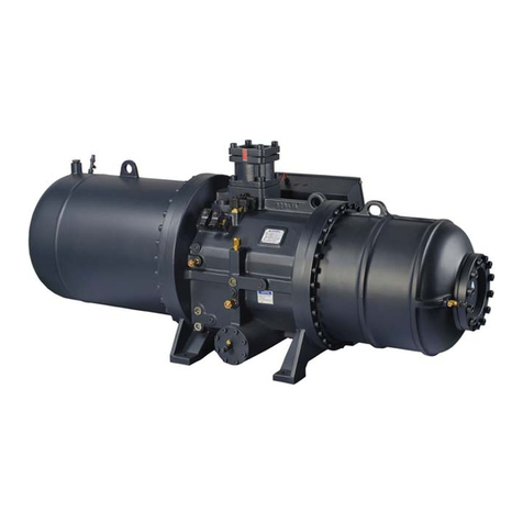
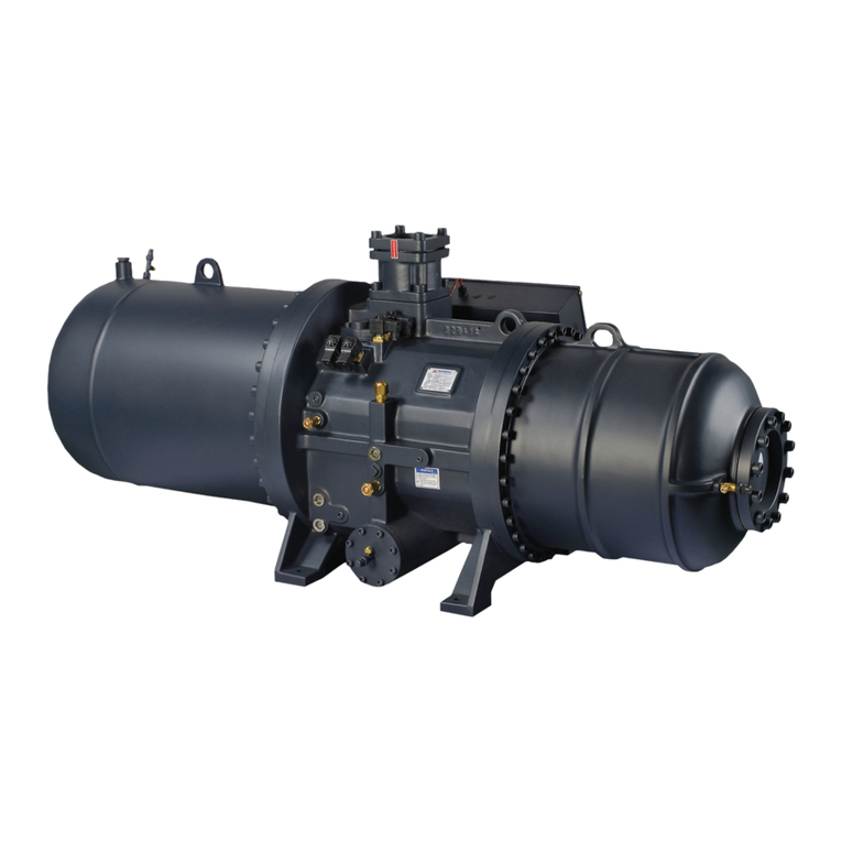
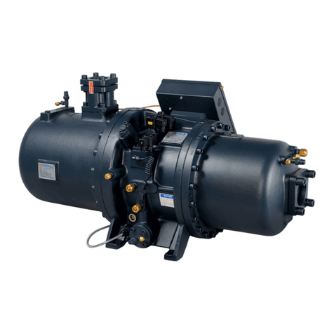
Hanbell LBII-PLUS User manual

LBII-PLUS Technical Manual
1
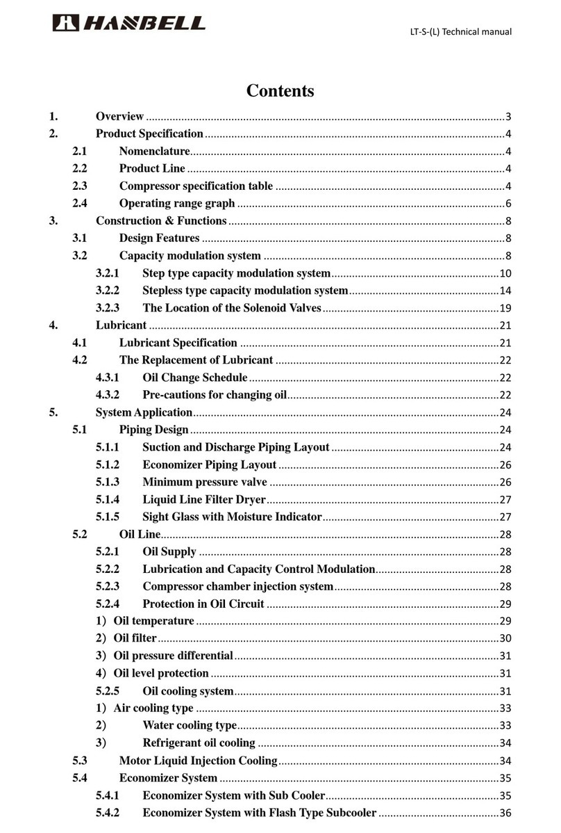
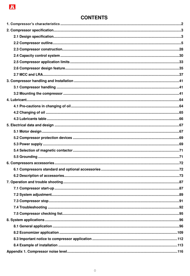
CONTENT
1. General ...................................................................................................................................................................... 3
1.1 Product Introduction...................................................................................................................................... 3
1.2 Nomenclature ................................................................................................................................................ 3
1.3 Product range................................................................................................................................................. 4
1.4 Design Specification ....................................................................................................................................... 4
1.5 Operation range ............................................................................................................................................. 5
1.6 Design Features.............................................................................................................................................. 6
2. Application................................................................................................................................................................. 7
2.1 Compressor application ................................................................................................................................. 7
2.2 Lubricant Application ..................................................................................................................................... 9
2.3 System application .......................................................................................................................................11
2.4 Motor control............................................................................................................................................... 21
2.5 Installation and fixation ............................................................................................................................... 24
3. Accessory................................................................................................................................................................. 26
3.1 Accessory list................................................................................................................................................ 26
3.2 Oil circuit parts............................................................................................................................................. 27
3.3 System parts................................................................................................................................................. 29
3.4 Electrical parts.............................................................................................................................................. 31
4. Maintenance............................................................................................................................................................38
4.1 Items to be checked before machine starting..............................................................................................38
4.2 Items to be checked during operation......................................................................................................... 38
4.3 Faults analysis ..............................................................................................................................................40
5. Appearance and functions.......................................................................................................................................42
5.1 Appearance structure ..................................................................................................................................42
5.2 LBII-100~410-PLUS Connector ................................................................................................................... 45
5.3 LBII-100~280-PLUS Dimension................................................................................................................... 46
5.4 LBII-100~280P-PLUS Dimension................................................................................................................. 47
5.5 LBII-360/410-PLUS Dimension ................................................................................................................... 48
LBII-PLUS Technical Manual
2
5.6 LBII-100~280-PLUS Dimension................................................................................................................... 49
5.7 LBII-100~280-P-PLUS Dimension................................................................................................................ 50
5.8 LBII-360/410-PLUS Dimension ................................................................................................................... 51

LBII-PLUS Technical Manual
3
1. General
1.1 Product Introduction
In recent years, Hanbell has launched LB, LB-PLUS series low temperature screw refrigeration compressor based
on the integrated application experience in low temperature field and customer demand. In order to further expand
the application field and reliability of products, LBII-PLUS series compressors are specially developed. LBII-PLUS
series compressors continue to use the automatic control function of LB-PLUS. On the premise of ensuring intelligent
application, LBII-PLUS series further optimize the motor cooling control logic and cooling structure, improve the
safety margin of LBII-PLUS, and further expand the operation range, so that LBII-PLUS can meet the application
requirements of air-cooled system. At the same time, it further improves the performance, so that LBII-PLUS can be
widely used in refrigeration, industrial process cooling, freeze-drying and other fields with sufficient competitiveness.
In general, LBII-PLUS is a new elite product of Hanbell in the of low temperature application field.
Compared with normal product, LBII-PLUS has different application modes; users must read the contents of
this manual carefully before using, installing, debugging and running. If you have any questions, please contact
Hanbell.
1.2 Nomenclature
LB II –XXX X –X –PLUS
2nd generation Displacement Motor Extra-code Upgraded model
Rated power: 380V/50Hz, if need other special voltage/frequency, please contact HANBELL.
The standard motor of LB-PLUS is PWS partial winding starting motor.
Single type——compressor with built-in oil separator, hereinafter referred to as "single type".
Parallel type——compressor without built-in oil separator, hereinafter referred to as "parallel type".
If the compressor belongs to single type, the extra-code is omitted.
When the compressor is applied for R22 refrigerant, the refrigerant code is omitted
Product Code 2950r/min(50HZ) Null: Standard motor Null: Single type
Unit: m3/h V: Converter motor P: Parallel type

LBII-PLUS Technical Manual
4
1.3 Product range
LBII-PLUS fixed frequency compressor
1.4 Design Specification
Table 1 Compressor Design Specification
Model
Compressor
Motor
Oil filling
volume
Oil heater
Strength
test
Weight
Displacement
50Hz m3/h
Rotation
50Hz r/min
Lubricant
Type
Start-up
Voltage(V)50Hz
Insulation
Protection
L
W
bar
Kg
LBII-100/ LBII-100-P
106
2950
Oil difference pressure supply
3 phase 2 pole squirrel-cage inductor motor
(frequency conversion motor optional)
Partial winding starting
380
Level F
PTC
+NTC
4.5
300
35
248/233
LBII-140/ LBII-140-P
139
7
290/275
LBII-180/ LBII-180-P
179
7.5
310/295
LBII-200/ LBII-200-P
198
10
440/420
LBII-230/ LBII-230-P
224
10
460/440
LBII-250/ LBII-250-P
257
10.5
464/446
LBII-280/ LBII-280-P
275
11
474/454
LBII-360-P
366
-
-
370
LBII-410-P
416
-
-
416
Remark: “-P”Type compressor without lubricant oil
Note: Please confirm the rated current of designed working condition according to the HANBELL model selection
program, and select the contactor, power line and fuse protection element according to the maximum operating
current value determined by the initial temperature / limit operation.
LBⅡ-100
LBⅡ-140
LBⅡ-180
LBⅡ-200
LBⅡ-230
LBⅡ-250
LBⅡ-280
LBⅡ-360
LBⅡ-410
106
139
179
198
224
257
275
366
416
0
50
100
150
200
250
300
350
400
450
m3/h

LBII-PLUS Technical Manual
5
1.5 Operation range

LBII-PLUS Technical Manual
6
1.6 Design Features
Electronic expansion valve
The LBII-PLUS adopts electronic expansion valve. Its precise control, stability in operation and
simplification control make compressors simpler, safer and more reliable.
Independent cooling of motor
It ensures that the motor runs at the ideal temperature, which effectively prolongs the life-time of
the motor. The harmful superheating of the suction refrigerant will no longer been increased. The
refrigerant after cooling the motor enters the compression chamber, so it will not cause the
cooling loss due to the cooling of motor, which achieves a higher energy efficiency ratio, especially
in the low temperature application.
Application design of single compressor and parallel connection
LBII-100~280-PLUS are divided into two structural forms: with oil separator and without oil
separator. LBII-360~410-PLUS have only one structure without oil separator. It can be applied to
various application fields, and different suction and discharge outlet directions can be selected.
The wiring part far away from the suction port to avoid affecting the electrical insulation
Compared with the normal low temperature screw compressor, the frosting phenomenon of the
electrical part is reduced, which improves the safety.
High efficiency multistage oil separator
Patented segmented high efficiency oil separator design ensures the lowest oil loss rate during the
compressor operation.
Optimization motor cooling
The motor cooling control logic of LBII is optimized and operation range is expanded to meet the
requirements of air-cooling applications.
Optimization of economizer connector
The connector of economizer is optimized, and the performance of LBII-PLUS with economizer is
improved compared with LB-PLUS.

LBII-PLUS Technical Manual
7
2. Application
2.1 Compressor applicationMotor cooling
The normal screw refrigeration compressor cool the motor through suction. When it works at low temperature
condition, the mass flow rate of refrigerant is very small. Refrigerant absorbs heat through the motor, resulting in a
lot of harmful superheat, which increases the specific volume of the refrigerant and leads to theloss of refrigerating
capacity.
The LBII-PLUS series compressor adopts independent motor cooling. The motor chamber and the compression
chamber are isolated, and only small amount of liquid refrigerant is used to cool the motor, which enables the motor
to work in the ideal temperature range. Meanwhile, it can prolong the life-time of motor. The gaseous refrigerant
after cooling the motor enters the compression chamber to avoid the refrigerating loss caused by the motor cooling.
The effect is particularly obvious at low temperature.
In order to effectively control the refrigerant quantity that enter into the motor chamber, HANBELL designed the
scheme to control the motor liquid injection:
Electronic expansion valve specially designed for LBII-PLUS
With electronic expansion valve to control the temperature of the motor is shown in the following Figure, the
solenoid valve and the compressor start or stop at the same time. The electronic expansion valve is controlled by
controller of LBII-PLUS. Through a special algorithm, the temperature of the motor is controlled at around 60℃.
The following are description of two types of injection points:
1)
The liquid taking point of the
motor liquid injection shall be
taken at the front and bottom
of the rising riser of main
liquid pipe
The main liquid pipe
is required to use
riser Piping after the
motor takes the liquid
point, so as to ensure
that when the system
is short of refrigerant,
there is still enough
liquid refrigerant to
cool the motor.
Motor
liquid
injection
E
C
O

LBII-PLUS Technical Manual
8
2)
Figure2-1 Electronic expansion valve installation diagram
It is forbidden to cut off the liquid injection of the motor during operation.
It is forbidden to turn on the liquid injection of the motor when the compressor stops.
The refrigerant extraction is introduced directly from the place after the dry filter of system, and the
extraction point must be before the economizer. The material of injection pipe shall be copper and
rubber pipe shall not be used.
Normally closed solenoid valve shall be used for the motor liquid injection.
The oil sight glass is used to confirm whether the refrigerant is full in pipe. It is strictly forbidden to run
the compressor when the pipe is not full with refrigerant or there are a lot of bubbles in pipe.
If there is insufficient refrigerant before start-up and commissioning, it is recommended to charge
refrigerant from the valve above the casing.
It is recommended that the high-pressure reservoir should be equipped with level switch to prevent
the leakage of fluorine after long-term operation of the system, resulting in insufficient cooling liquid
supply of motor and insufficient liquid supply of evaporator, resulting in overheating of motor and
discharge, and eventually leading to compressor failure.
It is recommended that the suction side and the motor side be insulated to avoid cooling loss.
Note: Compared with the compressor with normal suction cooling structure of motor, LBII-PLUS can improve the
motor cooling reliability while improving the energy efficiency after motor liquid injection in the above way. Even
if the system is short of fluorine, the low pressure is too low and the suction superheat is too high, the motor
cooling can still be effectively ensured. In this way, the user can have enough time to deal with the abnormal
warehouse temperature and fluorine deficiency in the system, while the compressor with normal motor cooling
structure will alarm or even fail before the user finds out the problem and handles it.
E
C
O
Motor
liquid
injection

LBII-PLUS Technical Manual
9
2.1.2 Oil line blocking pin
If an external oil cooler is required to a single type compressor, oil blocking pin needs to be installed in the
compressor. The function of the blocking pin is to block the oil internal cycle of the compressor, so as to realize the
establishment of external oil.
Figure2-1 Oil line blocking pin diagram
2.2Lubricant Application
2.2.1 Function of lubricant
The sealing oil film is formed between the rotors and the compression chamber and between the
male rotor and female rotor to reduce the leakage of the refrigerant gas from the high pressure side
to the low pressure side during the compression process.
The lubricant will absorb and take away the heat generated by the gas refrigerant during the
compression process and the heat generated by the mechanical movements among the bearings,
so as to ensure the long-term normal operation of the compressor and reduce the discharge
temperature.
To form the oil film among the bearings so as to ensure the operation of the bearing under normal
conditions.
Oil inlet
Oil line blocking pin
Oil outlet

LBII-PLUS Technical Manual
10
2.2.2 Specified lubricants for LBII-PLUS
Table-2 Lubricant specification
Refrigerant
R22
R404A/R507
Type
HBR-B03
HBR-B05
Proportion
1.01
0.957
Specific heat40 ℃(Kcal/kg K)
0.43
0.43
Note
HANBELL only acknowledge the specified lubricant as written in above table.
Minimum starting temperature of the lubricant: 20℃.
When the compressor stops, please open the oil heater (exclude long term stop).
Lubricating oil for other refrigerants can only be used after confirmation with Hanbell.
2.2.3 Requirements for use and replacement of lubricating oil
Before filling the lubricating oil, the system should be kept clean. After the initial operation of 2000 hours, it is
recommended to refill the lubricant once more to ensure the long-term operation of the compressor.
Lubricating oil is easy to absorb the moisture in the air, so it should be avoided to be exposed to the air.
In order to keep as minimum as possible water contained in the system, it is suggested that the system
needs to be heated and evacuated as long as possible when the lubricant is replaced.
The foreign matter in lubricating oil will cause the blockage of the oil circuit. Therefore, the oil filter must
be installed to the external oil circuit, and the pressure difference switch must be installed before and
after the filter. When the pressure difference value reaches the set point (1.5bar), the oil filter must be
replaced or cleaned.
If the compressor runs under high temperature working condition for a long time, it will accelerate the
deterioration of the lubricating oil. Please check the chemical performance of the lubricating oil regularly
and shorten the interval of oil exchange.
The acidification of lubricating oil will affect the life-time of motor. when the lubricating oil PH≤6, it should
be replaced. (Please replace the system dry filter at the same time to ensure the system is dry).
If the compressor motor is burned, it will produce acid harmful matter and debris, and they will be
brought into the system together. The inspection should be carried out. Oil filters and lubricants must be
changed many times until the cleanliness and acidity of the oil line reach the standard. The lubricating oil
status needs to be traced regularly. Please replace it if the cleanliness and acidity beyond the standard
range. Please pay attention to the cleanliness and dryness of the system as well.
Warning: If the lubricating oil that isn’t authorized by Hanbell is used for compressor, HANBELL
will not be responsible for the coming problems.

LBII-PLUS Technical Manual
11
2.3 System application
LBII-PLUS system layout: Single type

LBII-PLUS Technical Manual
12
LBII-PLUS system layout: Parallel type
Figure-8 Basic system configuration
Note: The motor liquid injection pipe of each compressor in parallel should take liquid from the main circuit pipe
independently to avoid the phenomenon of liquid grab.

LBII-PLUS Technical Manual
13
2.3.1 Suction and discharge pipe configuration
During normal operation, the vibration of the compressor is small, so there is no need for flexible connection
among suction and discharge pipelines, but the pipeline must have enough flexible length, and it needs to be
ensured that the suction and discharge pipeline will not generate stress on the compressor. It is suggested to use
copper pipes as suction and discharge pipes, because copper pipes can be used to reduce the vibration of the
pipeline when the compressor is running.
Discharge piping diagram-parallel system
Suction piping diagram-parallel system
Detail Drawing - 2
Detail Drawing - 3
Detail Drawing - 1
Stop valve
x x x
Detail 1

LBII-PLUS Technical Manual
14
The compressor is equipped with a suction filter, it is still suggested to install a suction filter on the suction pipe
and clean it regularly, so that it is convenient for cleaning and replacement, with double protection at the same time.
When the system starts to operate, if the pressure drop is found greater than 0.5bar, please clean up filter. If the filter
is found damaged, we need to replace it in time, and clean up the impurities in the pipeline. During installation,
please ensure the correct direction of the filter. The stop valve is suggested to be added at the inlet and outlet for
easy maintenance.
2.3.2 External oil circuit system
If the compressor operates under low temperature conditions and the lubricating oil does not have extra cooling,
it will be unable to meet the operation requirements because of the high oil temperature. At this time, it is suggested
to configure the external oil cooler which can reduce the discharge temperature, and can also prolong the life-time of
the system.
Note: The temperature of the inlet oil should not be higher than 60℃.
There are mainly 3 type of oil cooling system:
Air cooling type
Water cooling type
Refrigerant cooling type
The heat exchange data of the oil cooler can be obtained by the HANBELL model selection program. The limit
operating conditions should be taken into account, such as the maximum pressure difference (high condensation
temperature and low evaporation temperature).
x x x
Detail 2
Detail 3

LBII-PLUS Technical Manual
15
It is required that the pressure drop of the external oil circuit system should not be greater than 1bar, so as not
to affect the normal lubrication of the compressor.
Figure-Pipeline diagram of external oil system
Air cooling type
The fan accelerates the air flow passes the fin of oil cooler to cool the lubricating oil in the pipeline. The suggested
system layout is shown in the following figure. For pressure difference switch, please refer to chapter 3.2.5.
Figure - Air cooling type oil cooler for single system
Figure - Air cooling type oil cooling for parallel connection system

LBII-PLUS Technical Manual
16
来自蒸发器
至
冷
凝
器
入油口
油
冷
却
器
油
分
出水
进水
Icon
Description
Icon
Description
Suction filter
Oil cooler
Compressor
Oil separator
Check valve
Oil sight glass
Oil filter
Oil flow switch
Pressure difference
switch
Solenoid valve
Handle valve
Water cooling type
The cooling water circulates by the pump and takes the heat of the lubricating oil. The suggested system layout is
shown in following Figure. For the pressure difference switch of single system, please refer to Chapter 3.2.5.
Figure - Water cooling type oil cooler for single system
Figure - Water cooling type oil cooler for parallel connection system
Table 3 Illustration

LBII-PLUS Technical Manual
17
2.3.3 Configuration requirements and use of external oil circuit
1) The oil cooler is suggested to be installed near the compressor. Moreover, the position of the oil cooler shall
be lower than the oil level of the compressor and the oil separator, so as to prevent the lubricating oil from
flowing back to the compressor or the oil separator when the compressor stops, resulting in high oil level in
the oil separator and liquid compression during start-up that lead to the overflow of the compressor.
2) The returned oil temperature control device for oil cooler is necessary to ensure that the returned oil
temperature is controlled at 40℃~60℃.
3) The oil cooler must be used for the following working conditions
Low evaporation temperature (-20℃~-50℃)
High suction superheat (>15K)
Note: Regarding the load of the oil cooler, please refer to the data of HANBELL model selector. When
selecting, we must consider the limit oil cooling load in the working condition and consider the size of the
oil cooler.
Configuration suggestion:
1) When the system is under normal operation, the pressure difference between high and low pressure side
shall not be less than 4bar (if the oil pressure difference cannot be established for a long time, it is
suggested to use pressure maintenance valve).
2) In order to ensure the oil temperature in the specified range, a bypass oil circuit with solenoid valve shall
be connected between the inlet and outlet of the oil cooler. If the oil temperature is too low, open the
solenoid valve so that the oil will be heated. Meanwhile, it can effectively regulate the oil cooler load
under different conditions.
3) The oil solenoid valve is recommended to be installed near the oil inlet of the compressor to avoid the oil
flowing to the compression chamber when the compressors stop.
4) It is suggested that the oil pipeline should not bend too much to cause excessive pressure drop and poor
oil entry.
Figure LBII-100~280-PLUS Piping drawing of external oil cooling circuit

LBII-PLUS Technical Manual
18
Figure LBII-100~280-PLUS-P Piping drawing of external oil cooling circuit
Figure LBII-360/410-PLUS-P Piping drawing of external oil cooling circuit
Model
Single type
Parallel connection type
LBII-100~180-PLUS
3/8"
Main oil circuit:5/8”, Branch oil circuit:3/8"
LBII-200~280-PLUS
5/8"
Main oil circuit:1-1/8”, Branch oil circuit:5/8"
LBII-360/410-PLUS
/
Main oil circuit:1-1/8”, Branch oil circuit:5/8"
Oil circuit pipe size table
Connect to external
oil separator outlet
Connect to external
oil separator outlet
Oil flow switch
Solenoid valve
Pressure difference switch
Oil sight glass
Filter
Oil flow switch
Solenoid valve
Pressure difference switch
Oil sight glass
Filter

LBII-PLUS Technical Manual
19
2.3.4 Economizer
The economizer will further cool the refrigerant before it pass through the expansion valve of the system, which
increases the cooling capacity and efficiency of the system, especially in the working condition of high condensation
and low evaporation temperature.
Sub-cooling cycle economizer:
A heat exchanger is used as a liquid sub-cooling device to achieve the purpose of sub-cooling of liquid
refrigerant. A portion of the refrigerant will be drawn from the condenser pipe, which will enter the sub-cooler
through the expansion valve, absorbing the heat and evaporating, and exchange heat with the backflow liquid
refrigerant. After heat absorption, the superheated saturated vapor enters the medium pressure compression
section through the compressor's economic interface for compression. This type can effectively improve the quality
of the liquid refrigerant refrigeration unit, and at the same time, the discharge temperature can be effectively
reduced.
The selection of economizer:
The tube and shell type heat exchanger can be used as an economizer. Please select the load of the
economizer according to the relevant technical data in the HANBELL software.
The selection of economizer expansion valve:
If you want to get more valve selection guidance for economizer expansion valves, please contact
HANBELL.
The control model of economizer:
It is suggested that when the system starts to run stable, the high and low pressure ratio is greater than 3
or the low pressure side pressure reaches the set value, then the economic cycle can be opened in order
to avoid the lubricating oil in the compressor back to the economizer, producing extra vibration and noise,
even the crack of the pipe.
Figure - Economizer pipe diagram

LBII-PLUS Technical Manual
20
Suggestions for economizer pipe line:
1. The economizer (sub-cooler) should be installed below the compressor to prevent the liquid refrigerant
in the economizer flow back to the compressor during the shutdown.
2. Under the unstable operating conditions or when closing the economizer circuit, a part of the oil and
refrigerant will flow back to the pipeline of the economizer, so it is suggested to make a U-shape near
the pipe line of the economizer to have an upstream pipeline, leaving a 150mm upstream line distance.
3. Under low pressure ratio conditions, the airflow inside the compressor will flow back, which causes
abnormal vibration and noise, so it is suggested to install buffer (silencer) and check valve near the
inlet of the economizer.
4. Please use corresponding pipes according to the size of the economizer connector.
5. Besides the heat preservation requirements, we should pay attention to vibration of the pipelines.
2.3.5 Condensing pressure regulation
The compressor pressure difference valve between suction and discharge side shall achieve 4bar within 30
seconds after starting. If the pressure difference is too low, it will cause insufficient fuel supply, leading to the
compressor shutdown in a period of time after starting (oil flow and pressure differential protection). At this time, it
needs to do condensing pressure control, ensuring enough high and low pressure difference can be established
within a short period of time to ensure compressor oil supply. It is suggested to use HANBELL optional pressure
maintenance valve, and the pressure maintenance valve related information, please contact HANBELL. The following
conditions can cause a low differential pressure:
Too low ambient temperature, the condenser is installed outside and shutdown for a long time.
Single compressor start in parallel system.
Heat gas defrosting and reverse circulation.
Double stage system low pressure compressor.
2.3.6 Parallel system operation requirements
When the parallel system starts, the compressors will start one after another (two compressor is not
allowed to start at the same time), and the time interval should be above 30s.
When the compressors complete the start process and work stably, please observe if the lubricating oil
in the external oil separator is clear or not, and ensure the position of the oil in the high level. The oil
recovery temperature is controlled at 40~60℃.
After the compressor is running for a period of time, if the pressure drop of the external oil filter is
more than 1.5bar before and after the filter, the external oil filter core should be cleaned or replaced.
In the parallel system the compressors can share one external oil separator. It is suggested that the oil
filter and the oil flow switch can be configured separately for each compressor.
Table of contents
Other Hanbell Air Compressor manuals

Hanbell
Hanbell LT-S Series User manual

Hanbell
Hanbell RT Series User manual

Hanbell
Hanbell RC2-AVI Series User manual

Hanbell
Hanbell RC2 Series Installation manual

Hanbell
Hanbell SAM-285 User manual

Hanbell
Hanbell RC2 Series User manual

Hanbell
Hanbell RC2-D User manual

Hanbell
Hanbell RC2-F Series User manual

Hanbell
Hanbell RC2-100A User manual