Thermo King ThermoLite 401414 User manual

TK 56579-11-IS-EN (Rev. A, 10/20) ©2020 Trane Technolo ies 1
Applications:
• Precedent™ Trailer Units*
• SB Trailer Units (Bracket 401271 is also required and sold separately)
• Carrier™ Trailer Units (Kit 903364 is also required and sold separately)
Figure 1. 401414 Components Shown.
x 5
x 4
RCS1540-2
x 1 x 8
x 1
x 1 x 1
WARRANTY REGISTRATION - MAJOR SERVICE PARTS
1PART INFORMATION USE DIGITS ONLY
PART NUMBER PART DESCRIPTION UNIT SERIAL NUMBER
PART SERIAL NUMBER DATE INSTALLED (Numerals)
MO. DAY YEAR
UNIT MODEL
2DEALER INSTALL (to be filled out by Dealer only)
DEALER CODE CITY, STATE WORK ORDER/INVOICE NUMBER
CUSTOMER NAME CITY, STATE, ZIP
3 END USER INSTALL (to be filled out by End User only)
COMPANY NAME ADDRESS: CITY, STATE, ZIP
CONTACT NAME PHONE NUMBER
( )
WORK ORDER/INVOICE NUMBER
PART PURCHASED FROM DEALER NAME, LOCATION
WE CERTIFY THAT THE ABOVE INFORMATION IS COMPLETE AND ACCURATE TO THE BEST OF OUR KNOWLEDGE,
AND UNDERSTAND THAT THE INFORMATION ON THIS FORM MAY BE SUBJECT TO AUDIT.
WE CERTIFY THAT THE PART DESCRIBED ABOVE HAS BEEN DELIVERED IN SATISFACTORY OPERATING CONDITION WITH
ALL NECESSARY PRINTED MATERIAL AND THAT THE END USER HAS BEEN FAMILIARIZED WITH THE BASIC OPERATION,
MAINTENANCE REQUIREMENTS, AND PROVISIONS OF THE APPLICABLE WARRANTY.
X X
SIGNATURE OF DEALER SIGNATURE OF END USER
DEALER COPY
THERMO KING CORPORATION
314 WEST 90TH STREET • MINNEAPOLIS, MINNESOTA 55420
TK1073-3 (10-11)
ALTERNATOR ENGINE COMPRESSOR MICROPROCESSOR
STARTER INJECTION PUMP BATTERY OTHER
Solar Panel
Installation Manual
x 1 x 1
* Precedent units ordered from the factory with the solar panel option will include only the solar
panel in the box, the battery harness will be factory installed on the unit. All other applications
will come with the solar panel and battery harness to ether in the box.
Installation Instructions
ThermoLite™30W Solar Panel it 401414

2©2020 Trane Technolo ies TK 56579-11-IS-EN (Rev. A, 10/20)
Solar Panel Installation Best Practices
IImmppoorrttaanntt:: BEFORE beginning the solar panel installation disconnect all power to the
refrigeration unit including standby power (if equipped). lso disconnect all power at
the batteries for solar panel installation onto tractors or buses and on trailers
equipped with a lift gate
• Prior to installation, familiarize yourself with the components supplied in your kit.
• Follow installation instructions specific to your installation kit and model refri eration unit.
• Plan the solar panel layout and wire routin prior to permanently mountin any components.
• DO NOT block the solar panel with antennas, telematics modules, etc. This will reatly
reduce the output of the solar panel and inhibit its ability to supply power to maintain and
support the battery or batteries it is connect to.
• Make sure wire routes are free from abrasive materials and have adequate clearance from
hot surfaces.
• Holes used for routin harnesses throu h metal frames, skins or structures should be
smooth and non-marrin and lined with a rommet.
• Remove solar panel fuse (located on the solar panel harness) prior to panel installation.
•TTrraaccttoorr wwiitthh AAPPUU – DO NOT connect solar panels to TriPac Envidia APU Batteries.
• Solar panel electrical harnesses routed inside the refri eration unit must be secured to other
harnesses or to a solid frame structure with insulated clamps or cable ties to prevent makin
contact with rotatin or hot components.
• DO NOT attach electrical harnesses to copper tubin , exhaust components or fuel lines.
• Solar Panel Test Procedures must be performed to complete the installation.
• Fill out the Warranty Re istration Form after completin the installation.
Figure 2. DO NOT block the solar panel with antennas, telematics modules, etc.
RCS1634

TK 56579-11-IS-EN (Rev. A, 10/20) ©2020 Trane Technolo ies 3
SB Installations
IImmppoorrttaanntt:: BEFORE beginning the installation, refer to “Solar Panel Installation Best
Practices,” p. 2.
NNoottee:: SB Installations require dapter Bracket 401271 (sold separately) to install.
1. Attach adapter bracket ((440011227711)) to solar panel assembly usin supplied hardware as shown.
2. Position solar panel on top of unit towards the curbside avoidin the muffler, condenser air
outlet, and center mountin hole.
3. Usin the mountin bracket as a template, mark and drill three 1/4'' dia. holes in the top front
cap, and three 3/16'' dia. holes in the rear frame member.
NNoottee:: The charge controller for the 30W panel is located under the panel. If your controller has
LEDs, verify solar panel operation before securing panel onto unit. If panel is installed,
follow test procedure for non-LED controllers. See “Solar Panel Test Procedures,” p. 11 .
4. Install front tabs of solar panel under the top cap and secure panel with supplied hardware
(use bolts throu h top front cap, use rivets for the frame).
5. Route harness down the rear curbside frame member to the an led frame support and alon
the frame front member to the starter.
IImmppoorrttaanntt:: Do not attach wiring harnesses to the fuel lines.
6. Attach positive (white/red) wire to the positive terminal on the starter solenoid (terminal with
the battery cable attached).
7. Attach ne ative (black) wire to CH terminal on throttle solenoid.
8. Secure harness as required with band wraps and anchors.
NNoottee:: void drilling holes in plastic bulkhead.
9. Clean door surface and attach supplied nameplate as shown.
10.Reinstall battery harness fuse and reconnect all power to unit.
NNoottee:: Remaining kit components are not used.
Figure 3. Adapter bracket shown installed.
401271 bracket shown attached to solar panel
RCS1565

4©2020 Trane Technolo ies TK 56579-11-IS-EN (Rev. A, 10/20)
PRECEDENT Retrofit Installations
IImmppoorrttaanntt:: BEFORE beginning the installation, refer to “Solar Panel Installation Best
Practices,” p. 2.
MMoouunnttiinn HHoollee IInnffoorrmmaattiioonn::
• Units built before April 2018 do not have factory predrilled mountin holes on the top frame
channels for the solar panel option. These holes will need to be added by the installer.
• Units built after April 2018 do have mountin holes on the top frame channels – proceed to
Step 2.
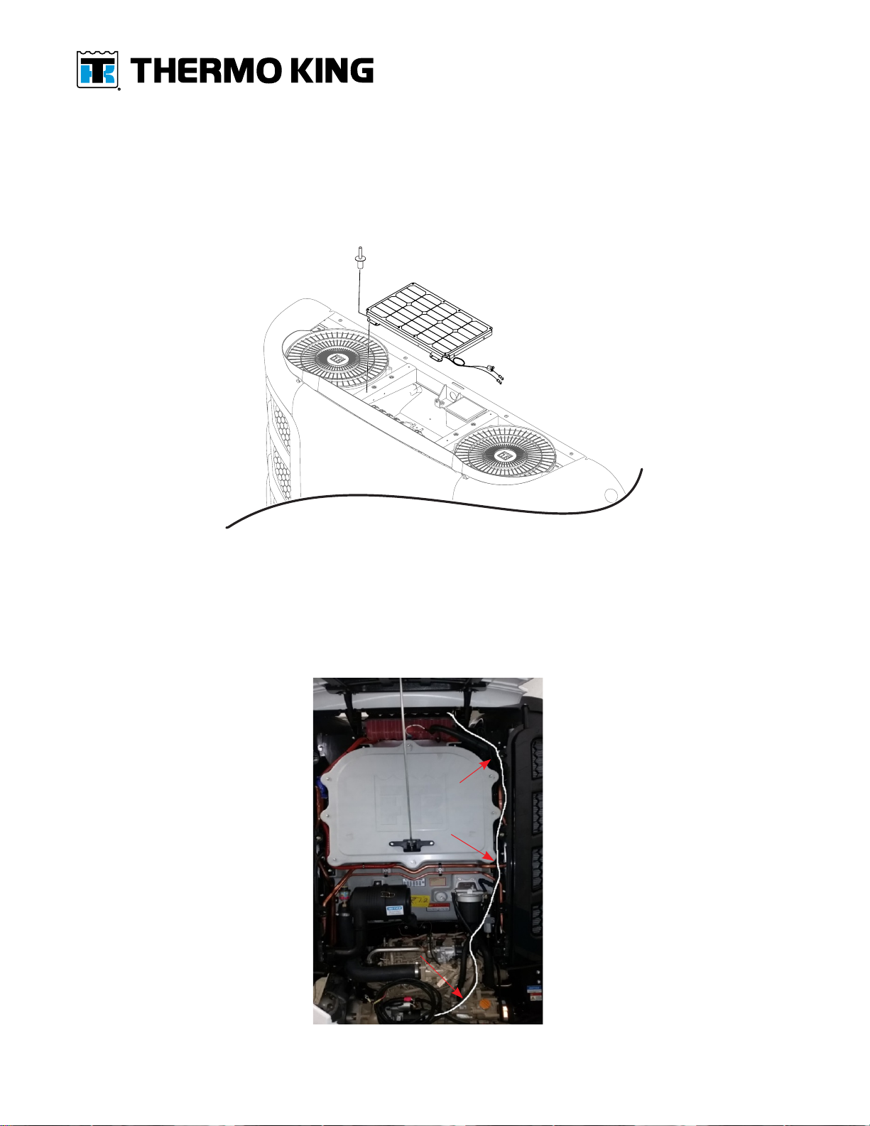
1. Position solar panel on top of unit between the condenser fans with the rear mountin tabs
a ainst the trailer wall:
a. Usin the mountin bracket as a template, mark and drill four 3/16'' dia. holes in locations
shown.
Figure 4. Mounting hole locations shown.
RCS1487-1
Mounting Locations
TK 56579-11-IS-EN (Rev. A, 10/20) ©2020 Trane Technolo ies 5
NNoottee:: The charge controller for the 30W panel is located under the panel. If your controller has
LEDs, verify solar panel operation before securing panel onto unit. If panel is installed,
follow test procedure for non-LED controllers. See “Solar Panel Test Procedures,” p. 11 .
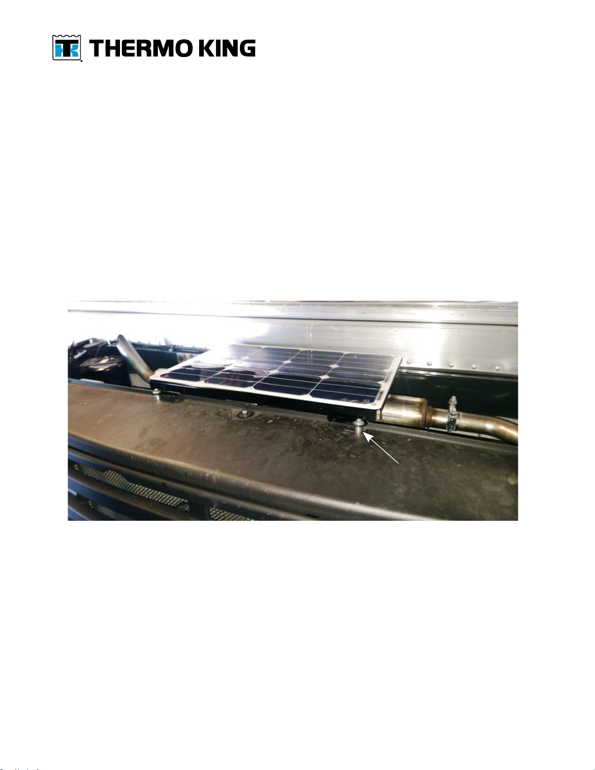
2. Secure solar panel to frame with supplied rivets.
Figure 5. Secure panel with rivets as shown.
RCS1500-1
3. Route harness down inside the unit, under the fuel filter and over to the starter as shown.
IImmppoorrttaanntt:: DO NOT attach electrical harnesses to copper tubing, exhaust components or
fuel lines.
Figure 6. Battery harness routing shown.
RCS1490

6©2020 Trane Technolo ies TK 56579-11-IS-EN (Rev. A, 10/20)
4. Attach positive (white/red) wire to the positive terminal on the starter solenoid (terminal with
the battery cable attached).
5. Secure the fuse holder to the existin harness.
Figure 7. Positive wire and fuse holder shown.
RCS1504
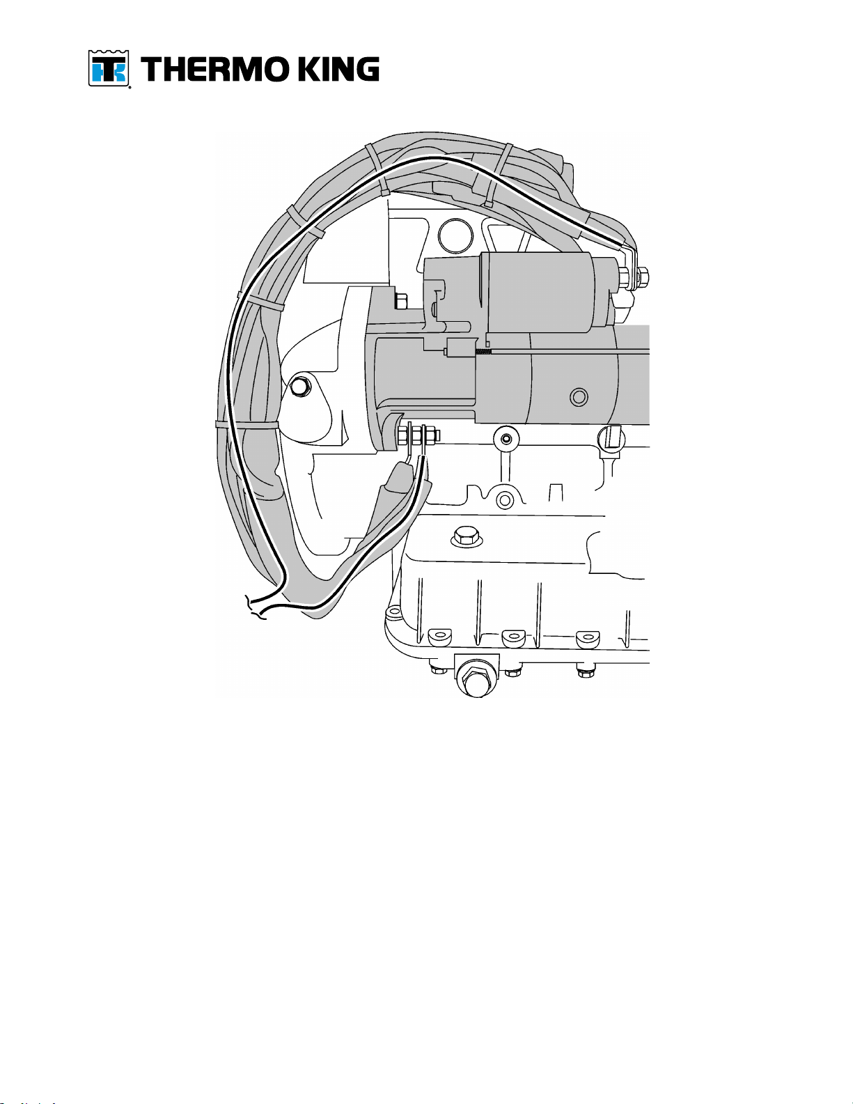
6. Attach ne ative (black) wire with terminal rin to en ine block round stud behind oil filter.
NNoottee:: The black wire with terminal ring should be installed under the flat washer followed by
the large ground cable and the external lock washer last.
Figure 8. Negative wire shown attached to engine block.
RCS1505

TK 56579-11-IS-EN (Rev. A, 10/20) ©2020 Trane Technolo ies 7
7. Coil up the extra harness len th in front of the starter and secure with supplied band wraps.
8. Clean door surface and attach supplied nameplate as shown.
9. Reinstall battery harness fuse and reconnect all power to unit.
NNoottee:: Remaining kit components are not used.
Figure 9. Install nameplate as shown.
RCS1501

8©2020 Trane Technolo ies TK 56579-11-IS-EN (Rev. A, 10/20)
PRECEDENT Installations (Ordered as Factory Option)
IImmppoorrttaanntt:: BEFORE beginning the installation, refer to “Solar Panel Installation Best
Practices,” p. 2.
NNoottee:: Precedent units ordered from the factory with the solar panel option will include only the
solar panel in a box, the battery harness will be factory installed on the unit.
1. Locate the battery harness connector on top of unit behind coolant tank.
a. Remove and discard the cap from the connector.
b. Attach connector to solar panel controller and secure harness to bracket with two band
wraps (supplied).
NNoottee:: The charge controller for the 30W panel is located under the panel. If your controller has
LEDs, verify solar panel operation before securing panel onto unit. If panel is installed,
follow test procedure for non-LED controllers. See “Solar Panel Test Procedures,” p. 11 .
2. Secure solar panel with supplied rivets usin the four predrilled holes in unit frame between
the condenser fans.
3. Clean door surface and attach supplied nameplate as shown.
4. Reinstall battery harness fuse and reconnect all power to unit.
NNoottee:: Remaining kit components are not used.
Figure 10. Connect battery harness to panel and secure panel to frame.
RCS1491-2
TK 56579-11-IS-EN (Rev. A, 10/20) ©2020 Trane Technolo ies 9
CARRIER™ Installations
IImmppoorrttaanntt:: BEFORE beginning the installation, refer to “Solar Panel Installation Best
Practices,” p. 2.
NNoottee:: Requires Optional Kit 903364 (sold separately) to install.
NNoottee:: The charge controller for the 30W panel is located under the panel. If your controller has
LEDs, verify solar panel operation before securing panel onto unit. If panel is installed,
follow test procedure for non-LED controllers. See “Solar Panel Test Procedures,” p. 11 .
1. Position solar panel on top of unit as shown with one aluminum spacer under each mountin
hole.
2. Secure panel to the front of the top cover and the rear frame member with the supplied self-
drillin screws.
Figure 11. Aluminum spacers shown installed.
RCS1488
Aluminum spacers and self-drilling screws 4x
3. Route harness down inside the unit and over to the starter.
4. Attach positive (white/red) wire to the positive terminal on the starter solenoid (terminal with
the battery cable attached).
5. Secure the fuse holder to an existin harness.
6. Attach ne ative (black) wire with terminal rin to the en ine block round stud.
NNoottee:: The black wire with terminal ring should be installed under the flat washer followed by
the large ground cable and the external lock washer last.
10 ©2020 Trane Technolo ies TK 56579-11-IS-EN (Rev. A, 10/20)
Figure 12. Harness connections at starter shown.
7. Coil up the extra harness len th in front of the starter and secure with band wraps.
8. Clean door surface and attach supplied nameplate.
9. Reinstall battery harness fuse and reconnect all power to unit.
10.Perform the “Solar Panel Test Procedures,” p. 11 to complete the installation.
NNoottee:: Remaining kit components are not used.
TK 56579-11-IS-EN (Rev. A, 10/20) ©2020 Trane Technolo ies 11
Solar Panel Test Procedures
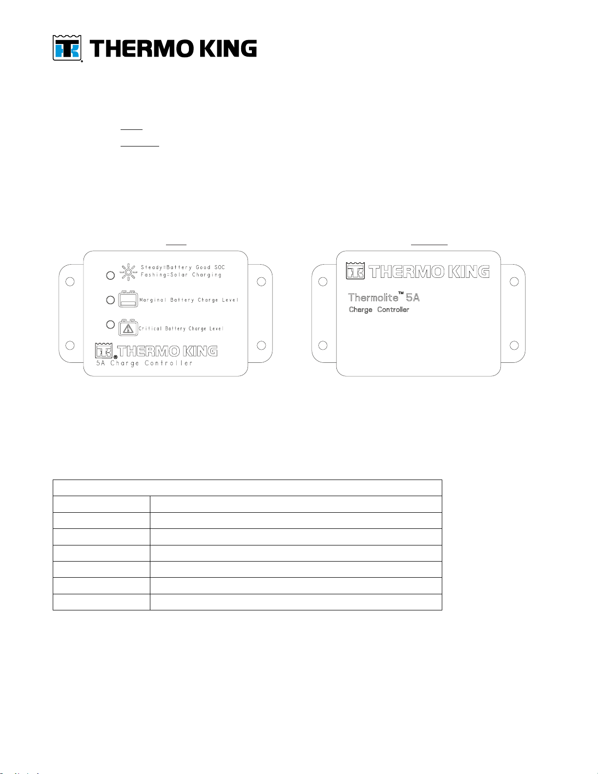
There are two types of 5A Char e Controllers:
1. Controller with LED status li hts.
2. Controller without LED status li hts.
The test procedures are different dependin on the type of char e controller you have.
NNoottee:: Charge controllers can take up to one minute to turn on.
Figure 13. Two Types of Battery Charge Controllers Shown.
5A Charge Controller with LED status lights 5A Charge Controller without LED status lights
RCS1633
CChhaarr ee CCoonnttrroolllleerr wwiitthh LLEEDD SSttaattuuss LLii hhttss
This char e controller has three LED status li hts that indicate battery char in and system
operation. If you have this version controller refer to the SSttaattuuss LLii hhtt FFuunnccttiioonn table below to
verify solar panel operation. Also see ““SSoollaarr PPaanneell TTrroouubblleesshhoooottiinn GGuuiiddee”” if necessary.
Status Light Function
Flashing Green Solar panel working properly and charging
Solid Green Battery fully charged
Flashing Yellow Marginal battery, charging
Solid Yellow Marginal battery, not charging (night time)
Flashing Red Extremely low battery, charging
Solid Red Extremely low battery, not charging (night time)
No light Controller not connected/extremely low or dead battery
CChhaarr ee CCoonnttrroolllleerr wwiitthhoouutt LLEEDD SSttaattuuss LLii hhttss
This char e controller does not have LED status li hts to indicate battery char in and system
operation. If you have this type of controller you must use the ““TTeesstt PPrroocceedduurree”” on the
followin pa e to verify solar panel operation. Also see ““SSoollaarr PPaanneell TTrroouubblleesshhoooottiinn GGuuiiddee””
if necessary.

12 ©2020 Trane Technolo ies TK 56579-11-IS-EN (Rev. A, 10/20)
Test Procedure
TToo pprrooppeerrllyy tteesstt tthhee ssoollaarr oouuttppuutt yyoouu mmuusstt hhaavvee tthhee ffoolllloowwiinn iitteemmss::
• Halo en lamp (500W or reater) or be outdoors in the dayli ht.
• Volta e meter
• Amp clamp or Ammeter
1. Attach voltmeter on the battery and measure the volta e.
• Volta e must be less than 12.8V for the solar panel controller to turn on.
• If battery volta e is not less than 12.8V, then put a 12V load on the battery.
Figure 14. Measure battery voltage.
!V < 12.8
12.8 V
!V ≥ 12.8
12 V
RCS1517
2. Move vehicle outdoors into the dayli ht. If indoors, put at least a 500W halo en lamp
approximately 24'' above the solar panel and turn lamp on.
NNoottee:: The solar panel controller may take up to a minute to turn on. The solar panel must be
connected to the battery in order to turn on the charge controller.
3. Attach voltmeter on the battery and measure the volta e.
a. Volta e readin should be in increasin or stay the same.
4. Place amp clamp around the positive cable from the solar panel.
a. Ampera e readin should be reater then 300 mA
Figure 15. Measure solar panel voltage and amperage readings.
12.0 V
300 mA
12
V –
>
300 mA
I –
>
-
+
500W
–
>
24.00
RCS1533-1

TK 56579-11-IS-EN (Rev. A, 10/20) ©2020 Trane Technolo ies 13
Solar Panel Troubleshooting Guide
Use the followin table to troubleshoot ThermoLite Solar Panel Systems.
STEP ACTION RESULT COMMENT
1Verify the system is connected to a battery. The system will not operate
if not connected to a
battery.
2 Verify the battery voltage is between 11V & 12.6V Either discharge or charge the
battery to the range for the
solar charge controller to
operate
The solar controller will
only operate if the battery
voltage is within the range
of 11V to 12.6V.
3 Verify system operation by exposing the panel to sufficient
light.
Any amount of sunlight (even
cloudy day) will result in some
current (>100mA) flowing to
the battery. This must be
verified with an amp clamp
around the positive cable to the
battery.
If tested inside, at least
500W of halogen light at a
range of about 12-24"
should be used. Ensure the
light shines on the entire
panel.
4Check if the fuse is present in the harness and verify
continuity
Ensure any replaced fuse is
rated at 20A.
5 Is the solar charge controller present in the system (applies to
36 & 100W systems)?
Once connected, the charge
controller will take up to 1
minute to turn on and start
charging. At this point current
will be flowing.
The absence of a charge
controller will result in
unregulated power input to
the battery that could
under or overcharge the
battery.
6 Verify cable polarity using the diagrams provided in the
installation instructions TK 56127 and TK 56237 (applies to 36
& 100W systems).
Cable Polarity is swapped in the
controller so the polarity from
start to finish must be checked.
If polarity is found to be wrong,
swap the pins in the extension
cable.
This is a common issue
during installation if the
connector is installed
backwards and the polarity
isn't checked.
7 Confirm cable integrity Check cable integrity to ensure
that abrasions, scrapes, or
breaks in the wire are not
affective voltage drop or power
loss.
Breaks in the power cable
anywhere along the line
will result in voltage or
power loss that will result in
ineffective charging.
8 Verify solar panel output (without charge controller) by
disconnecting the panel from the harness and checking
voltage output at the panel plug connector.
Unregulated panel output
voltage may range from
approximately 17V to 21V. If
the panel has low output
voltage then it's defective and
should be replaced.
Testing the panel output
will isolate the issue in the
system.
9Confirm charge controller functionality. With the panel in sunlight the
system should put out at least
200mAmps.
If all above tests are
confirmed then use an Amp
clamp with at least 3
decimal points around the
positive cable going to the
battery.

14 ©2020 Trane Technolo ies TK 56579-11-IS-EN (Rev. A, 10/20)

TK 56579-11-IS-EN (Rev. A, 10/20) ©2020 Trane Technolo ies 15
ThermoLite™ Solar Panel it Warranty
All ThermoLite solar panels installed by an authorized Thermo Kin dealer and re istered within
the first twelve (12) months of installation receive five (5) years parts and labor warranty
covera e from date of installation. ThermoLite solar panels installed by an authorized Thermo
Kin dealer not re istered in that time will automatically receive five (5) years plus 90 days parts
and labor covera e from date of manufacture.
Customer installed ThermoLite solar panels re istered within the first twelve (12) months of
installation receive five (5) years parts warranty covera e from date of installation. Customer
installed ThermoLite solar panels not re istered in that time will automatically receive five (5)
years plus 90 days parts covera e from date of manufacture.
Customer Satisfaction Survey
Let your voice be heard!
Your feedback will help improve our manuals. The survey is accessible throu h any internet-
connected device with a web browser.
Scan the Quick Response (QR) code or click or type the web address https://tranetechnolo ies.
iad1.qualtrics.com/jfe/form/SV_2octfSHoUJxsk6x?Q_CHL=qr&Q_JFE=qd to complete the
survey.
Table of contents
Other Thermo King Solar Panel manuals


Popular Solar Panel manuals by other brands


Hanwha SolarOne
Hanwha SolarOne HSL60P-PA-0-235K installation guide

Viessmann
Viessmann Vitosol 100 installation instructions

Viessmann
Viessmann VITOVOLT Operating Instructions for the System User

BenQ
BenQ PM200M00 installation guide

chromagen
chromagen Solar power owner's manual

Vision
Vision TZ58/1800-10 Installation, operation and maintenance guide


