Thermo King Ingersoll Rand ThermoLite EMEA 36W User manual

TK 61341-11-IM (Rev.3, 10/17) Copyright© 2015-2017 Thermo King, Climate Solutions EMEA
ThermoLite™ EMEA/NAD 36W / 100W SOLAR PANEL INSTALLATION
NOTE: Includes Trailer Applications and Domestic Refrigerated Container (DRC) Applications.
Kit Contents
NOTE: See illustration of these parts on the next page.
Item Description Qty
1. Solar Panel, 25” lead with Adhesive Backing 1
2. Cable, Extension SLX 140” 1
3. Charge Controller, In Line 1
4. Harness, Fused Terminal, 89” 1
5. Cable Tie, Nylon, 9’’ long, 0.140’’ wide, UV-resistant black 8
6. Clamp Tinnerman 1/4 x 3/8, 300 Stainless Steel with Extruded Neoprine Cushion 4
7. Screw-Hwhtc, 10-16 Szn , 0.75” Self Drilling 4
8. Screw, pan head M4 x 10 square cone sems SS 2
9. Nameplate, Solar Warning 1
10. Screw # 12-14 x 1-1/4 CHWH Self-Drill, w/ Sealing Washer 4
11. Christmas Tree Ratchet Fastner 0.187 x 0.675 (Drill 4.5 mm) (Plastic) 10
12. Bracket - Charge Controller 1
13. Blind-Rivet 1/8’’, 0.337 4
14. Rivet Multi-grip 3/16” x 0.04 - 0.75 10
15. Lockwasher 3/8”, Engine Ground 1
16. Flatwasher, 0.565 x 0.045”, Heat King Installation 2
17. Flatwasher, 3/8”, Engine ground 1
18. Grommet 0.687ID, 0.125 groove 1
Figure 1: 401305 Kit Contents

2
BEN137

3
General Installation Precautions and Specifications
For best results when applying the panel adhesive, ensure the surface is completely clean using Isopropal
alcohol or appropriate de-greasers. Ensure all cleaning residue is removed and the surface is dry.
IMPORTANT: The solar panel, application surface and air temperature must all be above 1.3 C.
• The adhesive backing is very aggressive and is difficult to remove once installed.
• Always ensure the solar panel fuse (located on the terminal connection harness) is removed during
installation and service.
• Locate the charge controller near the unit electrical connection to avoid voltage loss in the cable.
SLXi, SLXe, SLX Unit Installation (Trailer Applications)
1. Switch unit controls to the off position and disconnect the positive battery cable.
2. Temporarily remove the fuse from solar panel harness. (See Step 10 of Procedure)
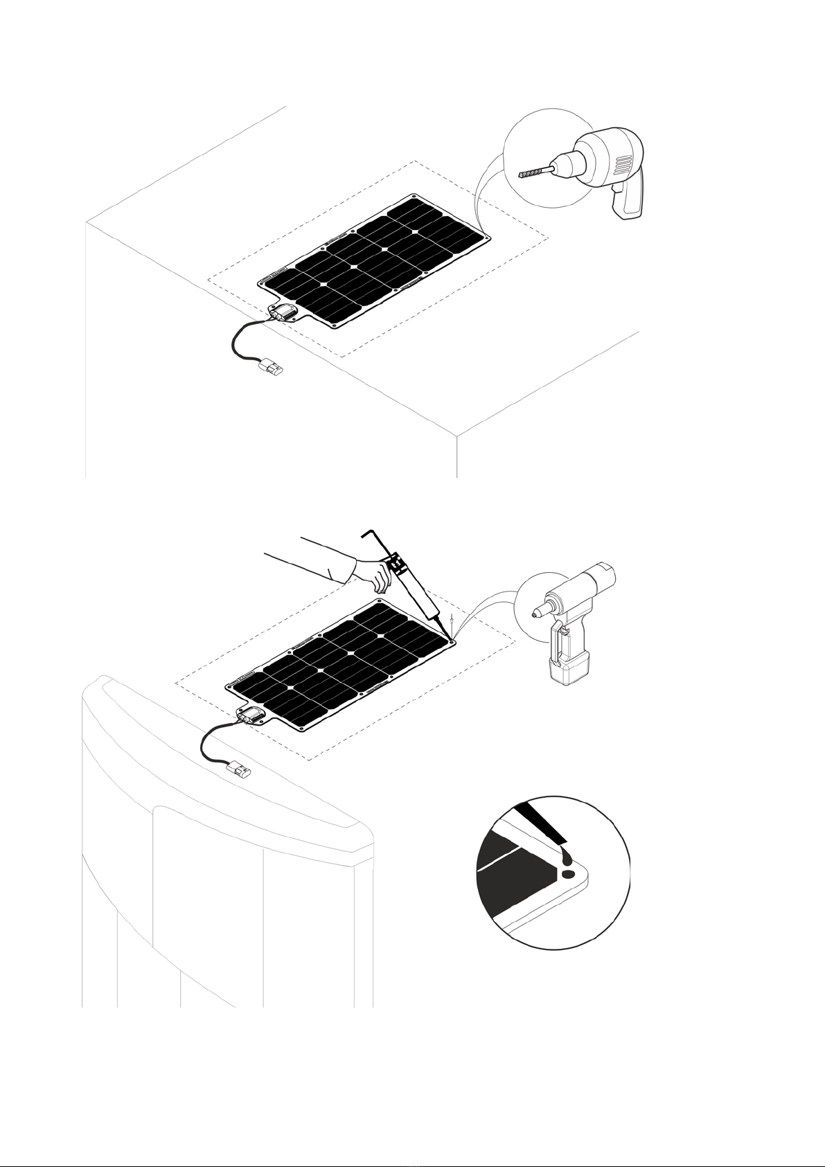
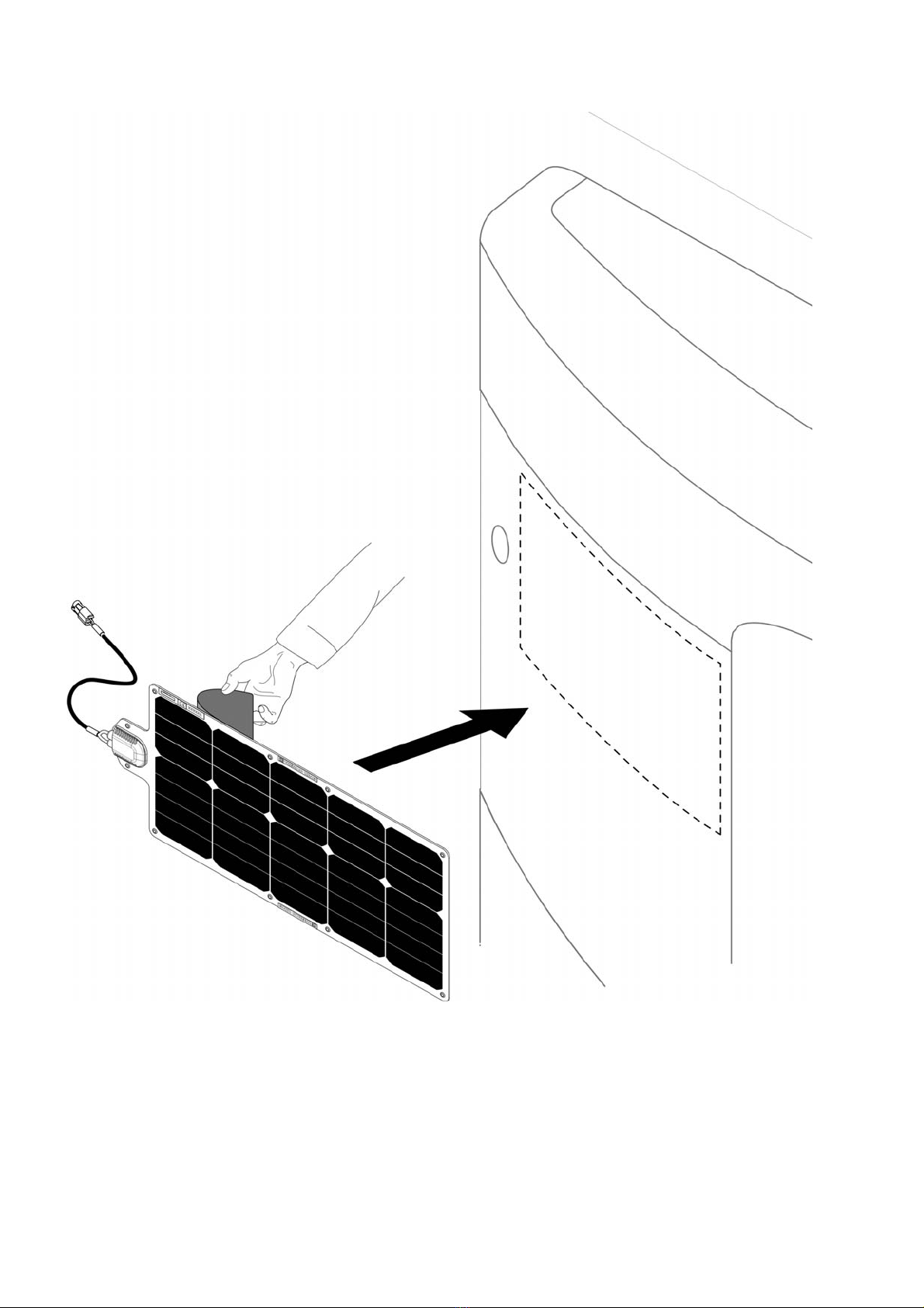
3. Prepare/clean an area on the top of the trailer body for the solar panel (see illustrated by dotted line below)
and position the panel as shown.
NOTE: Adhesive should not be used if the solar panel is to be transferred to another trailer - Use the
fasteners only.
CAUTION: Make sure that the surface temperature and the air temperature is above1.3 ° C.
.
WARNING: Always wear safety glasses and protective gloves when working with batteries.
BEN138
4
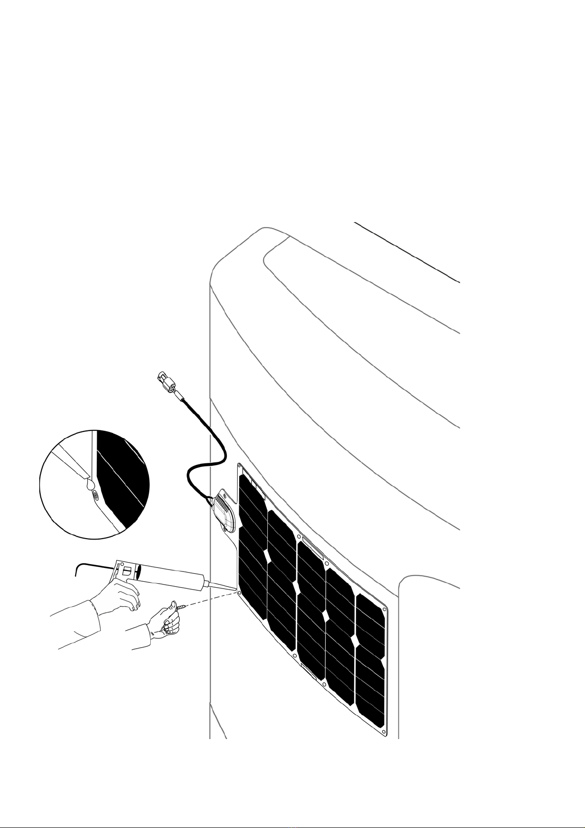
4. From Kit Contents, use item 14 (drill 5 mm) for each of the 10 positions to secure the panel to the trailer
body. If the trailer body is made of plastic, use item 11 (drill 4.5 mm) instead.
5. Apply Silicon Sealant (Outdoor Grade)
BEN139
BEN140
5
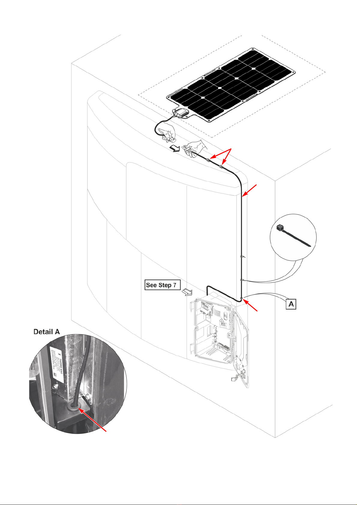
6. Routing Procedure - see below (see also Kit Contents at the beginning of the manual for Item numbers)
NOTE: Refer to Annex for more details
BEN141
Item 2
Item 18
Item 6
Item 5
Item 18

6
7. Install the bracket to the control box.
8. Install the Charge Controller to the bracket.
NOTE: Refer to Annex for more details
BEN363
Item 12
Item 8
BEN364
Item 3
Item 13
7
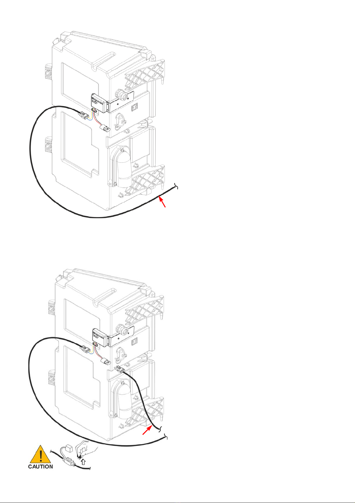
9. Connect the cable from the solar panel.
NOTE: Always ensure the solar panel fuse (located on the terminal connection harness) is removed during
installation and service.
10. Connect the Fused cable to the Charge Controller, route to the starter motor and make connections.
BEN365
Item 2
BEN142
Item 4
8
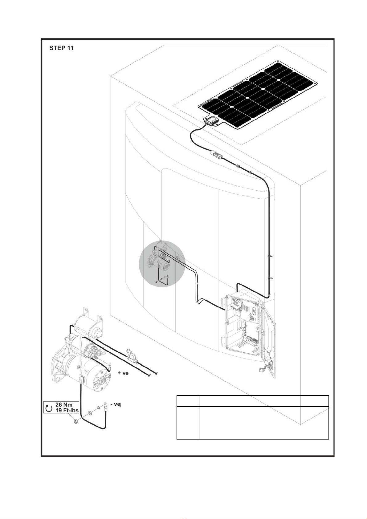
Harness Routing
CAUTION: Make sure that the harness is not damaged while routing.
NOTE: Refer to Annex for more details.
+ve Starter Solenoid
-ve Engine Block Ground
Make sure that the correct torque is
applied. 26 Nm/19ft-lbs
BEN143

9
CAUTION: Always temporarily remove the fuse from the harness while servicing the unit
13.Reinstall the harness fuse, connect the positive and negative battery cable and switch unit controls
to the on position.
BEN144
Item 9
BEN145

10
Domestic Refrigerated Containers (DRC)
NOTE: Please refer to “Kit Contents” on page 1 and “General Installation Precautions and Specifications”
on page 3 before commencing the installation.
1. Thoroughly clean unit surfaces.
2. Mark 0.50 in. from the edge of the door panel and 1.375 in. down from the top edge.
BEN366
11
3. Peel back approximately 4 inches of the liner and position solar panel onto door panel aligning it with the
marks made in step 2. Install solar panel securely to door panel.
BEN367
12
4. Secure at least the four corners of the solar panel.
a. Main Method
• Drill 3/16” (4 mm) holes at each panel grommet.
• Insert the christmas tree fasteners (up to 10 places) and push securely in place.
• Apply caulking around the fasteners.
b. Alternate Method
• Drill 5/32” (4 mm) holes at each panel grommet.
• Secure with #10- 14 x 1/2” long thread forming screws.
• Apply caulking around the screws.
BEN368

13
5. Mark 4.75 in. (120.6 mm) from the edge of the panel.
6. Drill hole 7/8” (22.5 mm) and install grommet.
WARNING: Do not drill holes into refrigeration, electrical, or mechanical components or severe damage to
equipment will result.
7. Insert solar panel connector through the grommeted hole.
8. Apply Caulking around the grommeted hole to seal.
BEN369
Item 18

14
9. Inside the unit, connect the extension cable, route the cable down the inside back channel, under the engine,
and across to the control box and battery area. Secure cable with tie bands to existing electrical cables.
BEN370
Item 6
Item 2
Item 5

15
10. Install the bracket to the control box.
11. Install the Charge Controller to the bracket.
NOTE: Refer to Annex for more details
BEN363
Item 12
Item 8
BEN364
Item 3
Item 13

16
12. Connect the cable from the solar panel.
NOTE: Always ensure the solar panel fuse (located on the terminal connection harness) is removed during
installation and service.
13. Connect the Fused cable to the Charge Controller.
BEN365
NOTE: After installation is
complete, it is advisable to coil up
any extra length of the Item 2
extension cable and secure with
cable tie. See “Routing Illustration
SLXi DRC” on page 17.
Item 2
BEN142
Item 4

17
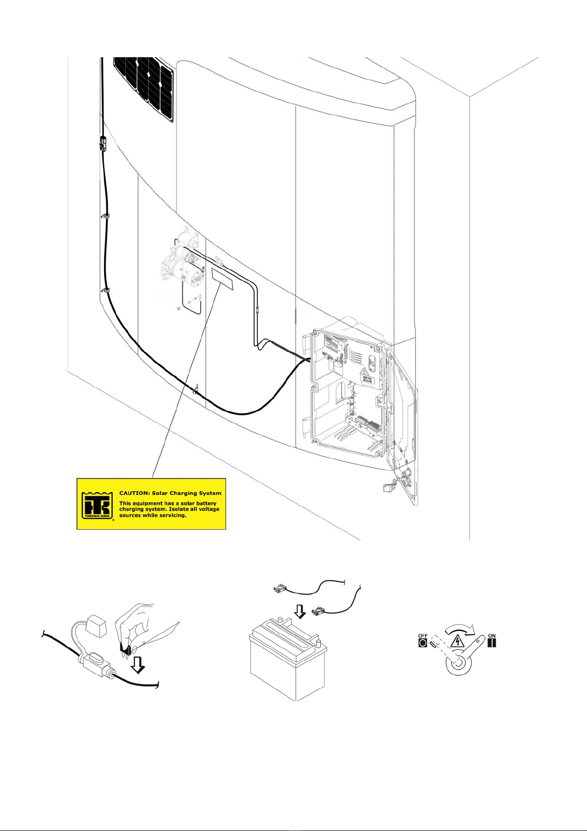
14. Route this cable to the starter motor and make connections.
Figure 2: Routing Illustration SLXi DRC
+ve Starter Solenoid
-ve Engine Block Ground
Make sure that the correct torque is
applied. 26 Nm/19ft-lbs BEN372
18
15. Install Solar Warning Nameplate in the location shown below.
16. Reinstall the harness fuse, connect the positive and negative battery cable and switch unit controls to the on
position.
BEN371
Item 9
BEN145
19
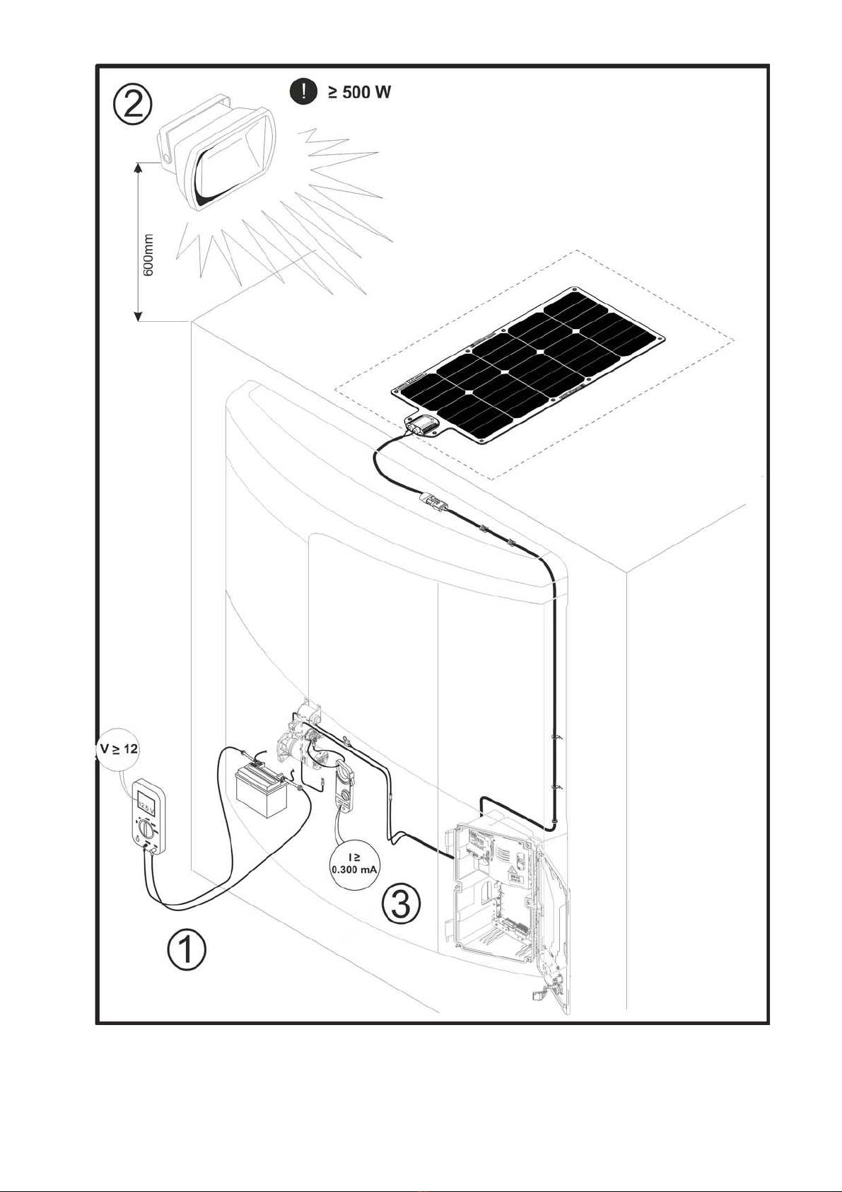
TEST PROCEDURE
NOTE: Trailer Application shown here for illustration purposes, however, the steps are the same for
Domestic Refrigerated Containers (DRC) application.
To properly test the solar output you must have the following items:
• Halogen lamp (500W or greater) or be outdoors in the daylight.
• Voltage meter
• Ammeter
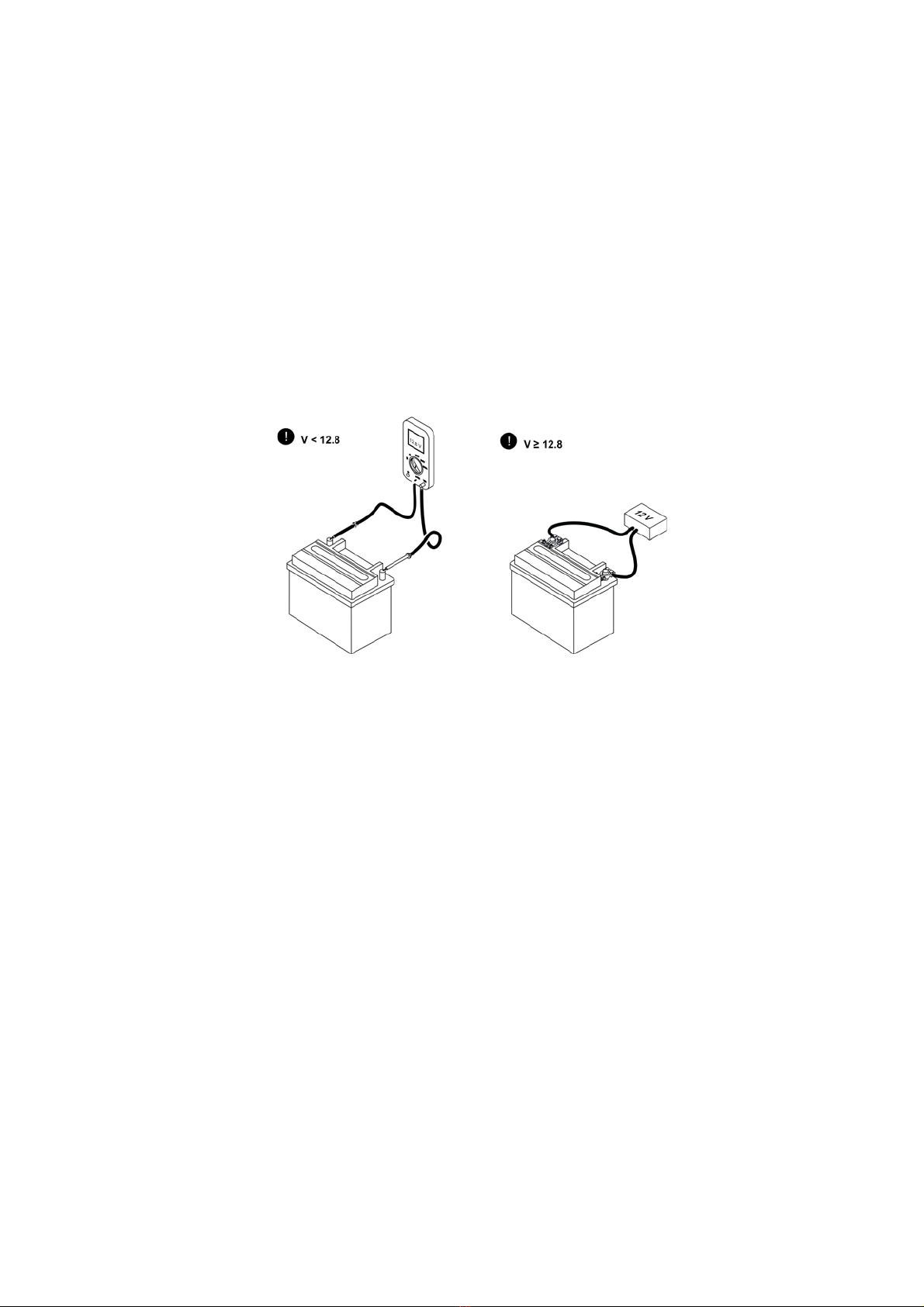
1. Put voltmeter on the battery and measure the voltage.
• Voltage must be less than 12.8V for the solar panel controller to turn on.
• If battery voltage is not less than 12.8V then put a 12V load on the battery.
2. If indoors, put at least a 500W halogen lamp approxiamately 600mm above the solar panel and
turn it on.
3. Put Ammeter around the positive cable from the solar panel.
• Voltage reading should begin increasing or stay the same.
• Amperage reading should be greater than 0.300 mA
NOTE: The solar panel controller may take up to a minute to turn on. The solar panel must be connected to
the battery in order to turn on the charge controller.
BEN146
20
Figure 3: Testing Connections
BEN147
This manual suits for next models
3
Table of contents
Other Thermo King Solar Panel manuals


Popular Solar Panel manuals by other brands


REC
REC TwinPeak 2S Mono 72 Series installation instructions

Flexsolar
Flexsolar C100 Instruction manual & warranty

Energizer
Energizer HardCase Sunpack 120W user guide

solarwatt
solarwatt EasyIn 60M Series installation instructions

Mission Solar Energy
Mission Solar Energy MONO Series Installation and user manual

Wiedenmann
Wiedenmann Favorit XP Translation of original operating instructions