Thermo Ramsey PRO-LINE 20-35U User manual


PRO-LINE
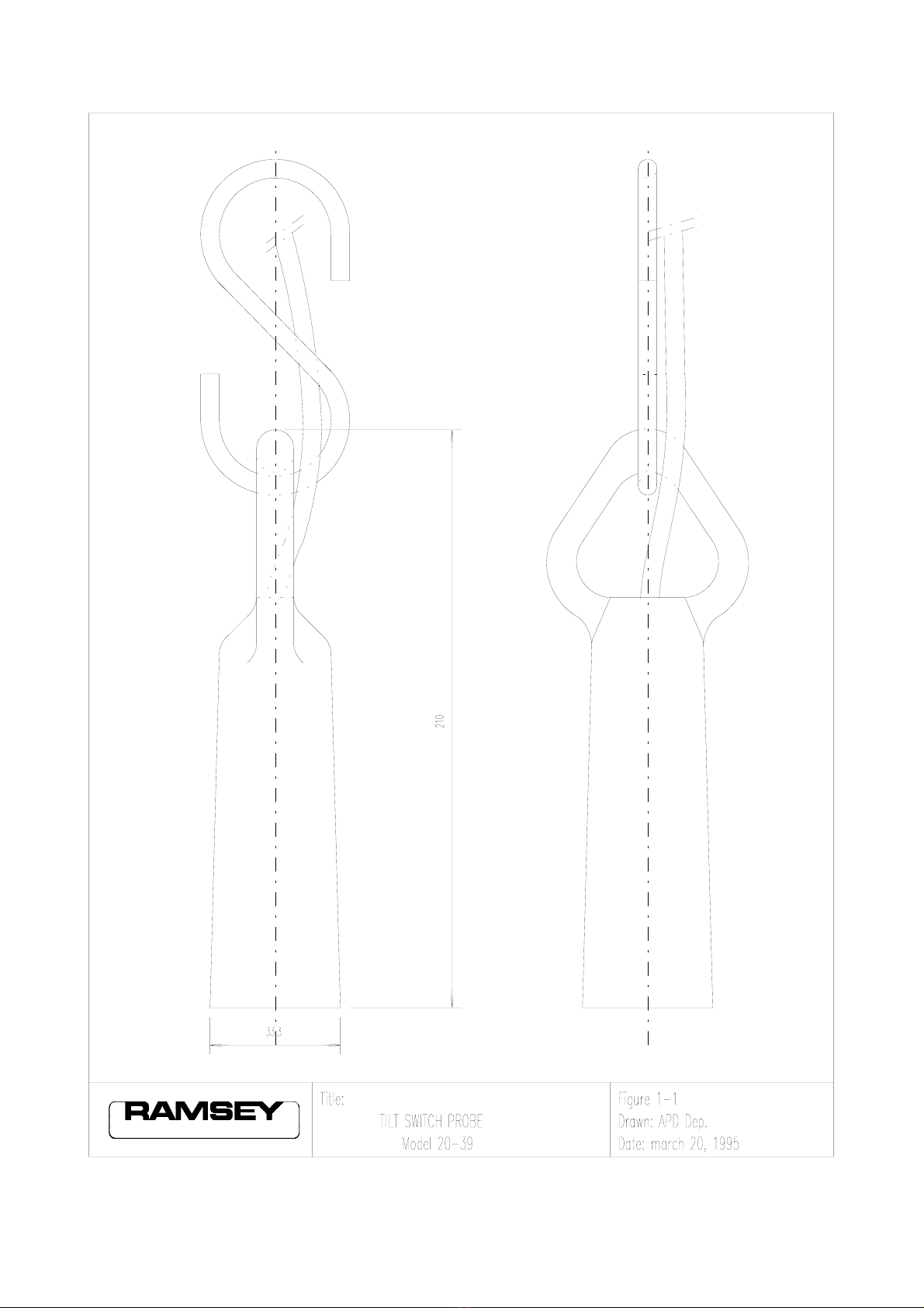
Tilt Switches
Model 20-39
with
Control Unit
Model 20-35U
INSTRUCTION MANUAL
THERMO RAMSEY GmbH Oberhausen, Germany tel.:+49(0)208-82493-0

1
Chapter 1
Tilt Switch Probe
1.1 Introduction
The Tilt Switch Probe actuates when it is tilted 12 - 15 degrees or more from its
vertical position. The Mercury Switch is precisely positioned so that regardless of di-
rection of Tilt the normally closed contact will open.
1.2 Specifications
(1) Contact: Normally closed
Mercury Switch
(2) Contact Rating: 1 Amp at 24 VDC
None inductive
(3) Temperature Ratings:
Standard - Model 20-39 : 30 - +80°C
HI Temp - Model 20-39HT: 20 - +200°C
(4) Housing: Ductile Iron
(5) Finish: Cadmium Plated
(6) Dimensions: See Figure 1-1
(7) Tilt Angle: 12° - 15°

2
Chapter 2
Tilt Switch Control
2.1 Introduction
The Control Unit is housed in an enclosure with large green ("Normal") and red
("Alarm") indicating lights on the front cover. A 0-5 second adjustable time delay
circuit in the control unit prevents momentary tilting of the switch from causing a
false or premature contact transfer. Two normally-open and two normally closed
output contacts are available for connection to external alarms and/or controls.
Interruption of line power causes a relay tranfer.
2.2 Specifications
(1) Power Requirements:
(A) Voltage : 110 / 220 VAC " 10 %
(B) Frequency : 50 Hz
(C) Consumption : 5.5 Watts
(2) Outputs:
One (1) DPDT contacts : Rated at 2 Amp at 250 VAC
(3) Time Delay:
Adjustable : 0-5 Seconds
(4) Input Resistance (resistance probe):
0.1 - 20 MOhm
(5) Selectable operation switch:
Permits reverse operation for either the tilt switch or the resistance probe.
(6) Enclosure:
Model 20-35U, IP 55
Model 20-35U pcba, none
(6) Dimensions - See Drawing PL 00 2035U ED 01

3
Chapter 3
Inspection and Installation
3.1 Inspection
Inspect the packages for external damage before opening as normally the carrier can
be held responsible for shipping damages. After unpacking, inspect the unit for bro-
ken components, etc.
3.2 Installation - Tilt Switch Probe
(1) Refer to Figure 1-1 for Dimensional Data
(2) Refer to Figure 3-1 for Installation Methods
3.3 Installation - Tilt Switch Control
(1) Refer to Figure 2-1 for Dimension Data
(2) The Control Unit should be mounted in a vibration free area. Where the
ambient temperature does not exceed 55EC.
3.4 Installation - Electrical
(1) The control unit enclosure is supplied with two
holes in the bottom for PG13,5 Conduit.
(2) Use seperate Conduit for probe and power circuits.
(3) Refer to Drawing PL 00 2035U ED 02 for wiring data.

4
Chapter 4
Set-Up and Adjustment
4.1 Tilt Switch Set-Up
Put the left dip-switch in the position – TILT –.
When the Tilt Switch System is used as a no flow detector the normal position of the
probe is tilted and when used as a level detector the normal position is vertical (not
tited). Because these uses are opposite each other, the right dip-switch must be
checked before applying power.
Refer to Drawing PL 00 2035U ED 02 for the location of the dip-switches.
Select from operational chart on the pcba the desired mode of operation, change the
position of the dip-
switches if necessary.
4.2 Resitance Probe Set-Up
Put the left dip-switch in the position – RESIS –.
Select from operational chart on the pcba the desired mode of operation, change the
position of the dip-
switches if necessary.
Fill the vessel up to the desired limit level and adjust the potentiometer – SENS – (see
drawing No.: PL 00 2035U ED 02) until the ALARM situation is monitored, or just
not monitored, depending on how critical this level is.
4.3 Delay Adjustment
This adjustment (potentiometer – DELAY –) will prevent
relay output contacts from transferring when probe is momentarily or falsely tripped.
The range of adjustment is 0-5 Seconds, because the
actual delay time is application dependent it must be adjusted at the time of
installation.
When setting this adjustment begin at the full C.C.W. pot (– DELAY –) position and
increase until false tripping is a minimum. A typical delay time is 3 seconds.

5
Chapter 5
Troubleshooting
5.1 General
The Tilt Switch control system has been designed to operate under normal Industrial
environments. The majority of
failures encountered have been the result of excessive
vibration, misapplication of the probe or switching excessive currents of voltages.
the operation of the Control unit may be checked by following the procedure.
Caution: when following the procedure, remember that if the unit is controlling other
equipment, the equipment concerned will either be shut down or started up, depending on
the application.
5.2 Troubleshooting Procedure
(1) Check supply voltage. The proper voltage must be applied to Terminals 1 and 2
(110VAC) or 1 and 3 (220VAC).
(2) Disconnect probe wires at Terminals 5 and 6.
(3) Turn time delay control (– DELAY –) completely CCW.
(Remember where it was set so that it may be returned to the same setting).
(4) Short across Terminals 5 and 6 (in tilt switch mode only). (There are no hazardous
voltages at these terminals). If the unit is operating properly, the following will
occur:
The relay will reverse its state.
The light that was illuminated will be de-energized and the one that was de-
energized will be
illuminated.
Relay operation may also be checked by disconnecting wires at
Terminals 7, 8 and 9 or 10, 11 and 12, and connecting an ohm-meter at
the terminals.

6
(5) Turn the time delay control slighty CW and repeat Step 4. The action as previously
observed should be repeated, however, the relay de-energized action will be
preceded by the delay period as set.
If the unit functions as described, the problem most likely is in the probe, its cable,
or field wiring
between the probe and the control unit. (This device may be checked with an ohm-
meter for proper operation). If the unit does not function as described, see the
Maintenance chapter.

7
Chapter 7
Maintenance, Spares and Repair
7.1 Gerneral
Except for the parts replacements mentioned below, Ramsey recommends that repairs not be
attempted on this unit.
Unauthorized repairs during the warranty period will void the warranty.
7.2 Suggest: Recommended Spares
(1) (1) Ramsey Model 20-35U pcba
(Complete Control less enclosure and Control Lights)
(2) (2) Lamps
7.3 Repair
Upon notification, Ramsey will repair and return within two (2) weeks after receipt of
equipment. Charges for repairing are based on time, material and handling.
8

9

10

11

12
This manual suits for next models
2
Table of contents
Popular Switch manuals by other brands


HP
HP E4510-48G Command reference guide

SMC Networks
SMC Networks SMC8624/48T Management guide

Extron electronics
Extron electronics MLS 608 D Series user guide

CEL-MAR
CEL-MAR ADA-4044H user manual

NETGEAR
NETGEAR GS748T - ProSafe Smart Switch installation guide

Dish Network
Dish Network Dish Pro 34 installation guide


