Thermo NESLAB RTE Series Owner's manual

Installation
Operation
Basic Maintenance
Thermo Manual P/N U00694
Rev. 05/20/04
NESLAB RTE Series
Refrigerated
Bath/Circulators
No part of this publication may be repro-
duced or reprinted except for personal use
without the prior permission of Thermo
Electron.

Table of Contents
Preface
Compliance .............................................................................................................. 2
After-sale Support.................................................................................................... 2
Unpacking ................................................................................................................ 3
Feedback ................................................................................................................. 3
Warranty................................................................................................................... 3
N S-care xtended Warranty Contract ................................................................... 3
Section I Safety
Warnings .................................................................................................................. 4
Section II General Information
Quick Reference Operating Procedures ................................................................. 6
Description ............................................................................................................... 7
Specifications ........................................................................................................... 7
Section III Installation and Operation
Site ......................................................................................................................... 11
lectrical Requirements ......................................................................................... 12
Plumbing Requirements ........................................................................................ 14
Fluids ..................................................................................................................... 16
Filling Requirements .............................................................................................. 17
Controller (Digital One/Digital Plus) ...................................................................... 17
Start Up/Shut Down ................................................................................................ 19
Setup/Tuning Loop ................................................................................................ 21
Controller (Digital Plus) ......................................................................................... 22
Computer Setup Loop .......................................................................................... 24
Timer Setup Loop .................................................................................................. 25
Offset Setup Loop .................................................................................................. 26
Analog A I/O Port - Optional ................................................................................... 27
High Temperature Cutouts ..................................................................................... 28
Nitrogen Purge ....................................................................................................... 29
Accessories ............................................................................................................ 29
Section IV Basic Maintenance
Reservoir Fluid ...................................................................................................... 33
Reservoir Cleaning ................................................................................................ 33
Algae ...................................................................................................................... 33
Condenser Cleaning .............................................................................................. 33
Internal Temperature Sensor (rtd1) Calibration .................................................... 34
xternal Temperature Sensor (rtd2) Calibration ................................................... 35
Optional Analog Port/Calibration - Optional .......................................................... 36
Section V Troubleshooting
rror Codes ........................................................................................................... 37
xternal Sensor Connector ................................................................................... 38
Checklist................................................................................................................. 39
Service Assistance ................................................................................................. 40
PID Values .............................................................................................................. 40
BOM Decoder ........................................................................................................ 41
Displaying Software Version Number .................................................................... 41
Appendix A luids
Appendix B NC Serial Communications Protocol
Appendix C International Quick Reference Operating Procedures
WARRANTY

- 2 -
Preface
Compliance
UL Listed to UL3101-1 (UL61010A-1)
Certified to CSA C22.2 No. 1010.1
Complies with IEC EN 61010-1
Products tested and found to be in compliance with the requirements defined in
the EMC standards defined by 89 336 EEC as well as Low Voltage Directive
(LVD) 73 23 EEC can be identified by the CE label on the rear of the unit. The
testing has demonstrated compliance with the following directives:
LVD, 73 23 EEC EN 610010-1:1993
EMC, 89 336 EEC EN 61326-1:1998
For any additional information, refer to the Letter of Compliance that shipped
with the unit (Declaration of Conformity).
After-sale Support
Thermo Electron Corporation is committed to customer service both during and
after the sale. If you have questions concerning the unit operation, contact our
Sales Department. If your unit fails to operate properly, or if you have questions
concerning spare parts or Service Contracts, contact our Service Department.
Before calling, please obtain the following information:
- unit BOM number_________________________________
- unit serial number ________________________________
- unit software version ______________________________
- voltage of power source ____________________________
The units BOM number and serial number are printed on the name plate label
located on the rear of the unit. See page 41 for instructions on how to decode
your unit's BOM number. See page 41 for instructions on how to display the
software version.
S/N: 101039026

- 3 -
Unpacking
Retain all cartons and packing material until the unit is operated and found to
be in good condition. If the unit shows external or internal damage contact the
transportation company and file a damage claim. Under ICC regulations, this is
your responsibility.
Feedback
We appreciate any feedback you can give us on this manual. Please e-mail us
at [email protected]. Be sure to include the manual part number
and the revision date listed on the front cover.
Warranty
Units have a warranty against defective parts and workmanship for 24 months
from date of shipment. See back page for more details.
NES-care Extended
Warranty Contract
Extend parts and labor coverage for an additional year.
Worry-free operation.
Control service costs.
Eliminate the need to generate repair orders.
No unexpected repair costs.
Other contract options are available. Please contact Thermo for more
information.

- 4 -
Section I Safety
Warnings
Warnings are posted throughout the manual. These warnings are designated
by an exclamation mark inside an equilateral triangle and text highlighted in
bold. Read and follow these important instructions. Failure to observe these
instructions can result in permanent damage to the unit, significant property
damage, or personal injury or death.
The lightning flash with arrow symbol, within an equilateral triangle, is intended
to alert the user to the presence of non-insulated "dangerous voltage" within
the unit's enclosure. The voltage may be of significant magnitude to constitute
a risk of electrical shock.
This label, engraved into the front of the tank lip, indicates the presence of hot
surfaces.
Make sure you read and understand all instructions and safety precautions
listed in this manual before installing or operating your unit. If you have any
questions concerning the operation of your unit or the information in this
manual, contact our Sales Department.
Performance of installation, operation, or maintenance procedures
other than those described in this manual may result in a hazardous
situation and may void the manufacturer's warranty.
Transport the unit with care. Sudden jolts or drops can damage the
refrigeration lines. The units weigh approximately RTE 7, 60 pounds (27
kilograms); RTE 10, 68 pounds (31 kilograms); RTE 17, 71 pounds (32
kilograms); RTE 740, 87 pounds (39 kilograms). Units should be trans-
ported with equipment designed to lift these weights.
Observe all warning labels.
Never remove warning labels.
Never operate damaged or leaking equipment.
Never operate the unit without bath fluid in the bath.
The user is responsible for the fluid used. Never use pure ethylene
glycol as a bath fluid, the flash point of 100% ethylene glycol is 111°C.
100% ethylene glycol may produce flammable vapors that can be
ignited by an open flame or an ignition source. When mixed with
water, ethylene glycol is not flammable. Also, at high temperatures
pure ethylene glycol may produce hazardous vapors.
Always turn off the unit and disconnect the line cord from the power
source before performing any service or maintenance procedures, or
before moving the unit.
Always empty the bath before moving the unit.
Never operate equipment with damaged line cords.
Refer service and repairs to a qualified technician.

- 5 -
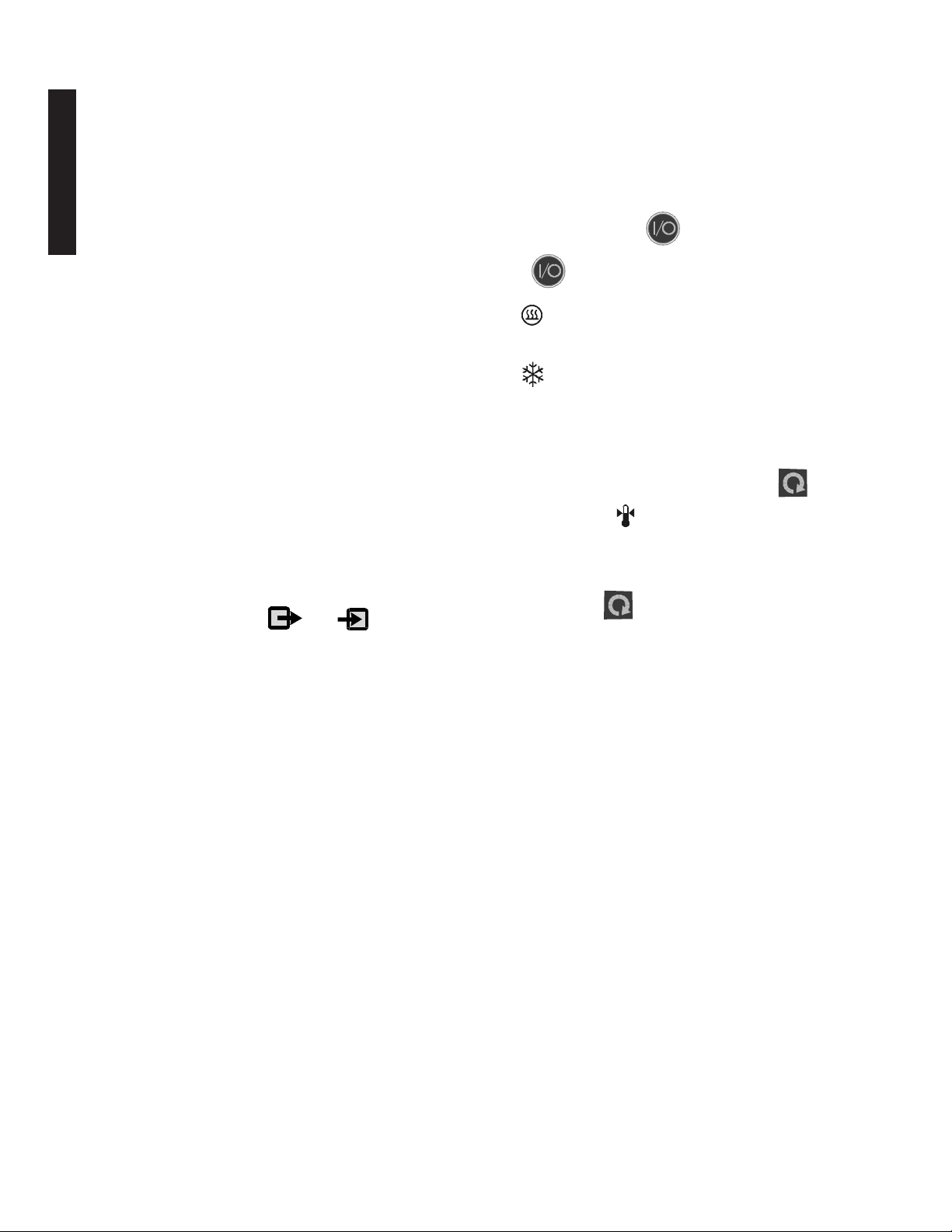
Circuit Breaker(s).
Reservoir. See page 16.
Controller. See page 17.
Condenser Access Panel.
See page 33.
Section II General Information
Indicates refrigeration
system status. See
page 17.
Indicates t e controller is
displaying t e setpoint. Press
t e arrow buttons to c ange t e
value. See page 18.
Indicates t e controller is
displaying t e unit's low
temperature alarm setpoint.
Press t e arrow buttons to
c ange t e value. See page 18.
Indicates t e controller is displaying
t e high temperature alarm
setpoint. Press t e arrow buttons
to c ange t e value. See page 18.
Press to select t e serial
communication mode.
See page 22. Digital Plus
controller only.
Press to change t e
displayed value. See
page 17.
Press to start/stop t e
unit. See page 17.
Press to mute t e alarm. See page
22. Digital Plus controller only.
Press to sequence
t roug t e t ree indicators
and accept t e displayed
value. See page 17.
NOTE: None of t e t ree
setpoint indicators are
visible unless t is key is
pressed.
Indicates heater status.
See page 17.
Press to select external
sensor. See page 22. Digital
Plus controller only.
Press to select t e timer
function. See page 23
Digital Plus controller
only.
Press to select t e
temperature offset
mode. See page 23.
Digital Plus controller only.
1/8"OD Autorefill fluid
connection. See page 29.
1/4" MPT Pumping
Return Connection. See
page 14.
Optional External Sensor
Connector. Digital Plus
controller only.
1/*4" MPT Pumping
Supply Connection. See
page 14.
RS-232/RS-485
connections. See
Appendix B. Digital
Plus controller only.
Power connection.
See page 12.
Drain. See page 14.
Hig Temperature Cutout.
See page 28.
1/8"OD N2 Nitrogen
Purge. See page 29.
General Information
Autorefill connection.
See page 29.
Analog Output
Connector. Digital
Plus controller only.
See page 27.
- 6 -
Quick Reference perating Procedures
Operation
Before starting the unit, double-check all electrical
and plumbing connections. Make sure the bath is
properly filled with fluid.
To start the unit, press . To turn the unit off
press again.
The LED indicates the status of the heater. It
illuminates to indicate the heater is on.
The LED indicates the status of the refrigera-
tion system. It illuminates to indicate the refrigera-
tion system is removing heat from the cooling fluid.
Temperature Adjustment
To display the temperature setpoint, press on
the controller. The indicator will illuminate and
the display will flash the current setpoint value. To
adjust the temperature setpoint, press the arrow
buttons until the desired temperature setpoint is
indicated. Press again to confirm the change.
The display will rapidly flash the new value for a
short time and then return to the recirculating fluid
temperature.
Periodic Maintenance
Periodically inspect the reservoir fluid. If cleaning is
necessary, flush the reservoir with a cleaning fluid
compatible with your application.
The reservoir fluid should be replaced periodically.
Frequency depends on the operating environment
and amount of usage.
Before changing the reservoir fluid ensure it is
at a safe handling temperature.
Periodic vacuuming of the condenser fins is neces-
sary. The frequency of cleaning depends on the
operating environment. We recommend a monthly
visual inspection of the condenser after initial
installation. After several months, the cleaning
frequency will be established.
Installation
Locate the unit on a sturdy work area. Ambient
temperatures should be inside the range of +50°F to
+104°F (+10°C to +40°C). The maximum operating
relative humidity is 80%.
Never place the unit in a location where excessive
heat, moisture, or corrosive materials are present.
The unit has an air-cooled refrigeration system. Air
is drawn through the front panel and discharged
through the rear panel. The unit must be positioned
so the air intake and discharge are not impeded. A
minimum clearance of 12 inches (30 centimeters) at
the front and rear of the unit is necessary for
adequate ventilation. Inadequate ventilation will
reduce cooling capacity and, in extreme cases, can
cause compressor failure.
Excessively dusty areas should be avoided and a
periodic cleaning scheduleshould be instituted.
The unit will retain its full rated capacity in ambient
temperatures up to approximately +75°F (+24°C).
Make sure the voltage of the power source meets
the specified voltage, ±10%.
The pump connections are located at the rear of the
pump box and are labelled and . These
connections are angled upward so the recirculating
fluid will drain back into the reservoir when the
hoses are disconnected. Both connections are
capped with stainless steel serrated plugs.
The pump lines have ¼" MPT for mating with
standard plumbing fittings. For your convenience
stainless steel adapters, ¼" FPT to 38" O.D.
serrated fitting, are provided.
The bath work area has a high and low level marker
to guide filling. The markers are 1 inch horizontal
slits located in the center of the stainless steel
baffle separating the work area and the pump
assembly. The correct fluid level falls between
these two markers. The unit will not start if the fluid
level is below the lower slit.
General Information

- 7 -
Description
The NESLAB RTE Refrigerated Bath Circulators are designed to provide
temperature control for applications requiring a fluid work area or pumping to an
external system. Units consist of a non-CFC air-cooled refrigeration system,
circulation pump, seamless stainless steel bath, work area cover, and a micro-
processor temperature controller.
Specifications1
Temperature Range2
Temperature Stability3
Cooling Capacity4,
Pump Capacity4
RTE 7 RTE 10 RTE 17 RTE 740
-25°C to +150°C -22°C to +150°C -40°C to +200°C
±0.01°C
General Information
-40-30-20-10 0 10 20 30 40 5060 7080 90100
Temperature °C
1100
1000
900
800
700
600
500
400
300
200
100
Heat Removal (Watts)
A=115/60 RTE-740 units
B=230/50 RTE-740 units
C=RTE-7, 10, 17
A
B
C
P
r
e
s
s
u
r
e
Meters Feet
4.9 16
3.7 12
2.4 8
1.2 4
0.8 1.6 2.4 3.2 4.0 Gpm
3691215Lpm
Flow

- 8 -
Time to Temperature
115V/60 Hz units
230V/50 Hz units
RTE-740 units
General Information

- 9 -
RTE 7 RTE 10 RTE 17 RTE 740
658 x 7¼ x 6
16.8 x 18.3 x 15.2
8¾x 9 38 x 6
22.4 x 23.9 x 15.2
8¾ x 9 38 x 9
22.4 x 23.9 x 22.9
1.9
7.2
2.6
9.8
4.5
17.0
658 x 7¼ x 6
16.8 x 18.3 x 15.2
1.9
7.2
200170
60
27.2
68
30.8
71
32.2
87
39.5
R134a (6 ounces) R404a (8 ounces)
Heater (Watts)
115V/60 Hz Models
230V/50 Hz Models
100V/50-60Hz Models
Refrigerant
Bath Work Area5
(W x L x )
Inches
Centimeters
Bath Volume
Gallons
Liters
Air Flow Requirements
SCFM
Weight5
Pounds
Kilograms
General Information
1. Specifications subject to change.
2. Baths are tested at temperatures below freezing with denatured alcohol. This fluid is HIGH Y
flammable and is not recommended by Thermo. Above 80°C, baths are tested at with silicone
oil. This fluid is known to release a formaldehyde vapor (which is carcinogenic) above 150°C.
3. 20°C ambient. 20°C bath temperature using water. Sea level. Measured at the center of the
work area, work cover on, no external flow, stable ambient, full refrigeration (RTE-740 in
Energy Saving Mode). For some applications, agitation and stability above ambient may be
improved by connecting a small length of hose between the pump connections on the rear of
the unit.
4. 20°C ambient. 20°C bath temperature using water. Pump fully loaded. Sea level.
5. See next page for unit dimensions.
6. Add approximately 3 pounds (1.4 kilograms) for shipping weight.
800 1600 800
2000 2000 2000
800 1200 800

- 10 -
Unitl Dimensions (inches)
General Information
B
A
C
1½
E
D
F
30°
½
Rear View Side View
105° 17/8
7/8
1
3¼
15/8
Unit Dimensions
Dimension A
Dimension B
Dimension C
Dimension D
Dimension E
Crate Dimensions
(D x W x H)
RTE 7 RTE 10 RTE 17 RTE 740
23 5/8 23 5/8 26 5/8 26 5/8
9 1/4 11 3/8 11 3/8 11 3/8
19 20 1/8 20 1/8 20 1/8
17 3/8 17 3/8 20 3/8 20 3/8
10 5/8 10 5/8 10 5/8 12 3/8
26½ x 18 x 33½

- 11 -
Section III Installation and Operation
Site
Locate the unit on a sturdy work area. Ambient temperatures should be inside
the range of +50°F to +104°F (+10°C to +40°C). The maximum operating
relative humidity is 80%.
Never place the unit in a location where excessive heat, moisture, or
corrosive materials are present.
The unit has an air-cooled refrigeration system. Air is drawn through the
front panel and discharged through the rear panel. The unit must be
positioned so the air intake and discharge are not impeded. A minimum
clearance of 12 inches (30 centimeters) at the front and rear of the unit is
necessary for adequate ventilation. Inadequate ventilation will reduce
cooling capacity and, in extreme cases, can cause compressor failure.
Excessively dusty areas should be avoided and a periodic cleaning schedule
should be instituted (see Section IV, Condenser Cleaning).
Using 20°C water as a bath fluid, 115 60 units will retain their full rated capac-
ity in ambient temperatures up to +20°C. Reduce the cooling capacity approxi-
mately 15 watts for every 1°C above +20°C, to a maximum ambient tempera-
ture of +40°C. For 230 50 units, reduce the cooling capacity approximately 18
watts for every 1°C. Lower reductions in cooling capacity occur as the bath
fluid temperature increases.
Installation and Operation

- 12 -
Electrical
Requirements
The unit construction provides protection against the risk of electrical
shock by grounding appropriate metal parts. The protection may not
function unless the power cord is connected to a properly grounded
outlet. It is the user's responsibility to assure a proper ground connec-
tion is provided.
We recommend the use of a dedicated outlet.
Refer to the serial number label on the rear of the unit to identify the specific
electrical requirements of your unit. Ensure the voltage of the power source
meets the specified voltage, ±10%.
The RTE-7 is not designed to be used beyond the voltage range or have
momentary power interruptions. Install an un-interruptible power supply or a
line loss detection method.
All units are:
Pollution Category 2
Overcurrent Protection II
The following power options are available:
Unit Amps1Breaker Power Inlet
RTE 7 115 60 1 12 15A IEC 320-C-13
100 50-60 1 12 15A IEC 320-C-13
230 50 1 12 15A IEC 320-C-19
RTE 10 115 60 1 12 15A IEC 320-C-13
100 50-60 1 12 15A IEC 320-C-13
230 50 1 12 15A IEC 320-C-19
RTE 17 115 60 1 16 20A IEC 320-C-19
100 50-60 1 16 20A IEC 320-C-19
230 50 1 12 15A IEC 320-C-19
RTE 740 115 60 1 16 20A IEC 320-C-19
100 50-60 1 16 20A IEC 320-C-19
230 50 1 12 15A IEC 320-C-19
Installation and Operation
1. Average Amp draw.

- 13 -
1. Power cord length, if supplied, is 2 meters.
Unit Type1Amperage Plug Type
115 60 1 15 NEMA 5-15
115 60 1 20 NEMA 5-20
100 50-60 1 15 NEMA 5-15
100 50-60 1 20 NEMA 5-20
230 50 1 All Country Specific
Installation and Operation
Power Cord Set
230 Volt, 50 Hertz units do not come with a power cord set. To select the
proper power cord, follow these guidelines:
nThe cord set must consist of a plug, cable and receptacle.
nIf the unit is rated greater than 12 Amps, use a cord set rated for 20A.
nIf the unit is rated less than 12 Amps, use a cord set rated for 15A.
nThe cord set must be approved by local electrical authority or other
acceptable agency.
nEnsure the plug is compatible with your local outlets and receptacles.

- 14 -
Installation and Operation
Plumbing Requirements
Ensure the unit is off before connecting tubing to the unit.
To prevent damage to the plumbing lines, always support the fittings
while installing/removing the pumping caps and lines.
Hose Connections
The pump connections are located at the rear of the pump box and are labelled
(pump outlet) and (pump inlet). These connections are bent upward
so the recirculating fluid will drain back into the reservoir when the hoses are
disconnected. Both connections are capped with stainless steel serrated plugs.
The pump lines have ¼" MPT for mating with standard plumbing fittings. For
your convenience stainless steel adapters, ¼" FPT to 38" O.D. serrated fitting,
are provided. (To assure proper fit, they should be installed using 1½ turns of
Teflon® tape around the threads.)
Make sure all tubing connections are securely clamped. Avoid running
tubing near radiators, hot water pipes, etc. If substantial lengths of tubing
are necessary, insulation may be required to prevent loss of cooling capacity.
Tubing and insulation are available from Thermo. Contact our Sales Department
for more information (see Preface, After-sale Support).
It is important to keep the distance between the unit and the external system
as short as possible, and to use the largest diameter tubing practical. Tubing
should be straight and without bends. If diameter reductions must be made,
make them at the inlet and outlet of the external system, not at the unit.
If substantial lengths of cooling lines are required, they should be pre-filled with
bath fluid before connecting them to the unit. This will ensure that an adequate
amount of fluid will be in the bath once it is in operation.
Drain
Ensure the bath fluid is at a safe handling temperature before draining
the unit.
The unit is equipped with a drain located at the back of the unit labelled .
To drain the reservoir attach a hose to the barb and loosen the fitting.
The fitting has a stop to prevent it from coming off.
Pumping
The pump is designed to deliver a flow of 15 liters per minute (4 gallons per
minute) at 0 feet head. To prevent external circulation, the pump inlet and
outlet lines on the rear of the unit are capped. The caps must be removed when
external circulation is required.
To properly secure external hose connections to the unit, wrap Teflon® tape
around the pipe line threads before installation. Once the hose connections are
made, the hoses must be properly plumbed to an external system. It is
important the bath is not in operation until all plumbing is complete.

- 15 -
Circulating to an open container
A stainless steel leveling device is available to aid circulation to an open
vessel. Contact our Sales Department for more information (see Preface).
Support the leveling device over the open container with a ringstand. Stagger
the tubes in the leveling device so one tube is submerged in the vessel fluid,
and the other tube is level with the fluid surface. Connect the deeper tube to
the pump outlet and the shorter tube to the pump inlet.
Adjust the flow rate using the accessory flow control valve connected to the
pump outlet, or by partially restricting the outlet tubing. When properly
adjusted, the pump inlet will draw an occasional air bubble to prevent over
flow, and the pump outlet will force fluid through the submerged tube to
prevent aeration of the vessel.
To avoid siphoning the bath work area when the unit is shut off, lift the
leveling device out of the vessel and above the level of the unit.
Circulating through two closed-loops
The pump can be used to circulate through two closed-loop systems. Connect
the shortest practical length of flexible tubing from the pump outlet to the inlet
of external system #1. Connect the outlet of system #1 directly into the bath
work area. Connect tubing from the bath work area to the inlet of system #2.
Connect the outlet of system #2 to the pump inlet.
System #1
System #2
Bath
Work Area
Pump Box
Bath (Top View)
Bath (Rear View) Open Container
Outlet Inlet
evelling
Device
Installation and Operation

- 16 -
Installation and Operation
Fluids
The user is always responsible for the fluid used. Never use flammable
or corrosive fluids with this unit. The use of chlorine or sodium
hypochlorite in the baths will cause pitting that could leave to failure of
the refrigeration system.
Handling and disposal of liquids other than water should be done in
accordance with the fluid manufacturers specification and/or the MSDS
for the fluid used.
For fluid selection consider application requirements, operating temperature
range, material compatibility, safety concerns, and environmental issues.
Wetted materials of bath include; 316 and 304 Stainless steels, Ryton® (PPS),
Teflon®(PTFE) and Ethlyene-Propylene rubber (EPDM).
Deionized (up to 18 Meg-ohm cm) and distilled water are recommended to
control corrosion and algae bloom. See Water Quality Standards and Recom-
mendation in Appendix A.
Ethylene glycol, propylene glycol, silicone oil, and filtered water are acceptable
fluids.
NOTE Kinematic viscosity of the selected fluid should not exceed 50
centistokes at the lowest operating temperature.
Please call Thermo customer service to discuss high and low temperature fluid
selections. However, we will often refer you to chemical companies specializ-
ing in heat transfer fluids.
Filling
Requirements
Ensure the drain on the back of the unit is closed before filling the unit.
The bath work area has a high and low level marker to guide filling. The
markers are 1 inch horizontal slits located in the center of the stainless steel
baffle separating the work area and the pump assembly. The correct fluid
level falls between these two markers.
NOTE The unit is equipped with a reservoir level float switch. The switch
prevents the unit from starting if the fluid is below the lower slit.
When pumping to an external system, keep extra fluid on hand to maintain
the proper level in both the circulating lines and the external system.
Avoid overfilling, fluids expand when heated.

- 17 -
Controller
(Digital One/Digital Plus)
The controller controls temperature using a Proportional-Integral-Derivative
(PID) algorithm. It is designed with self-diagnostic features and easy to use
operator interface. Two controller options are available: Digital One and Digital
Plus. The information on the following two pages applies to both controllers.
ON/OFF. Use this key to toggle the unit on or off and to clear error mes-
sages.
SCROLL. Use this key to scroll through the controller's LEDs. It is also
used to save new changes.
YES/ARROW. Use this key to increment numerical values when setting
values and to accept new settings.
NO/ARROW. Use this key to decrement numerical values when setting
values and to abort new settings.
Indicates refrigeration system status. It illuminates to indicate the refrigeration
system is removing heat from the bath fluid. The indicator is off when heat is not
being removed.
Indicates heater status. It illuminates to indicate the heater is adding heat from
the bath fluid. The indicator is off when heat is not being added.
Digital One Controller
Yes
No
Installation and Operation

- 18 -
Installation and Operation
NOTE The following indications are not visible until is depressed.
Setpoint. Indicates the controller is displaying the current setpoint.
Low Temperature Alarm. Indicates the controller is displaying the current
low temperature alarm.
High Temperature Alarm. Indicates the controller is displaying the current
high temperature alarm.
To adjust the displayed value use the arrow buttons. Pressing an arrow button
will cause the display to stop flashing and to indicate the new setpoint value.
Save the change by pressing SCROLL. The new setpoint value will rapidly flash
for two cycles and then the controller will return to the reservoir fluid tempera-
ture display.
If SCROLL is not pressed within 60 seconds the change will time out and revert
to the original setpoint. The controller will automatically return to the reservoir
fluid temperature display.
NOTE You can not adjust the setpoint closer than 0.1°C of either temperature
limit, and you can not adjust either temperature limit within 0.1°C of the
setpoint. Trying to do so will cause the indicator to flash and, on Digital Plus
controllers, the alarm to beep.
On units with the Digital Plus controller, pressing the Mute button prior to
pressing SCROLL will abort any changes and return to the reservoir fluid
temperature display.

- 19 -
Start Up/Shut Do n
(Digital One/Digital Plus)
Before starting the unit, recheck all electrical and plumbing connections.
Ensure the bath reservoir is properly filled. The unit will not start if the reservoir
fluid level is below the lower horizontal slit.
The unit can be configured for automatic restart. If the unit shuts down as
a result of a losing power, once power is restored the unit will restart.
See Setup/Tuning Loop on page 21 to enable this feature.
Press . The controller does a self-test (sequences through the LEDs, and
Digital Plus units momentarily sound the alarm), then quickly displays the
setpoint before displaying the reservoir fluid temperature. The pump starts and,
after a 30 second delay, the refrigeration comes on. The RTE-740 refrigeration
system is designed to start with the pump.
NOTE If the unit's recirculating fluid is outside either temperature limit, the unit
will start but the appropriate indicator will flash until the fluid is within the limit.
If refrigeration is needed for operation above 50°C, turn on the Full Range
Cooling Mode. See Setup Tuning Loop on page 21 to enable this feature.
To display change the setpoint press until illuminates. The display
will flash the current setpoint value. Use the arrow buttons to change the value.
The controller will not allow you to enter a setpoint closer than 0.1°C of either
temperature alarm setting, see next page. Attempting to causes the indicator
to flash and, on Digital Plus controllers, sounds the alarm.
Once an arrow button is depressed starts to flash. If an arrow button is not
pressed within 10 seconds the display will return to the reservoir temperature.
On units with the Digital Plus controller, pressing Mute prior to pressing
SCROLL will abort any change and return you to the fluid temperature display.
Once the desired setpoint is displayed, press again to confirm the
change. The display will rapidly flash the new value twice and then return to the
recirculating fluid temperature. If the new value is not confirmed within 60
seconds the display will return to the fluid temperature and ignore any change.
Controller
Pre-Start
Starting
Setpoint
Installation and Operation
Full Range Cooling
This manual suits for next models
4
Table of contents
Other Thermo Chiller manuals


Popular Chiller manuals by other brands

Carrier
Carrier 30HR Series Wiring diagrams

CIAT
CIAT POWERCIAT2 LXC instruction manual

Johnson Controls
Johnson Controls York YCAL0014E Series Installation, operation & maintenance instructions

VALERA
VALERA GM 21-C TRIPLE DOOR datasheet

Husky
Husky C Series user manual

Henny Penny
Henny Penny BCF-24 Operator's manual


Carrier
Carrier 30HH Installation and maintenance instructions

Carrier
Carrier PH4G-K Series installation instructions

AAON
AAON LF Series Installation operation & maintenance

HL
HL HL-i Series Use and maintenance handbook

Carel
Carel pCO1 series instructions

Carrier
Carrier GEMINI 09DPS018 Installation, start-up and maintenance instructions