Thermo NESLAB HX 150 User manual

Refrigeration
Service
Thermo Manual P/N U00058
Rev. 09/09/97
NESLAB HX 150
Recirculating Chiller
No part of this publication may be
reproduced or reprinted except for
personal use without the prior permission
of Thermo Electron.

2
Contents
General Information
After Sale Support ..................................................................................................... 2
CAUTION .................................................................................................................. 3
Theory of operation ................................................................................................... 4
Cool mode ............................................................................................................ 4
Heat/idle mode...................................................................................................... 5
Troubleshooting
Troubleshooting Chart: Runaway cold ...................................................................... 6
Troubleshooting Chart: Runaway hot........................................................................ 7
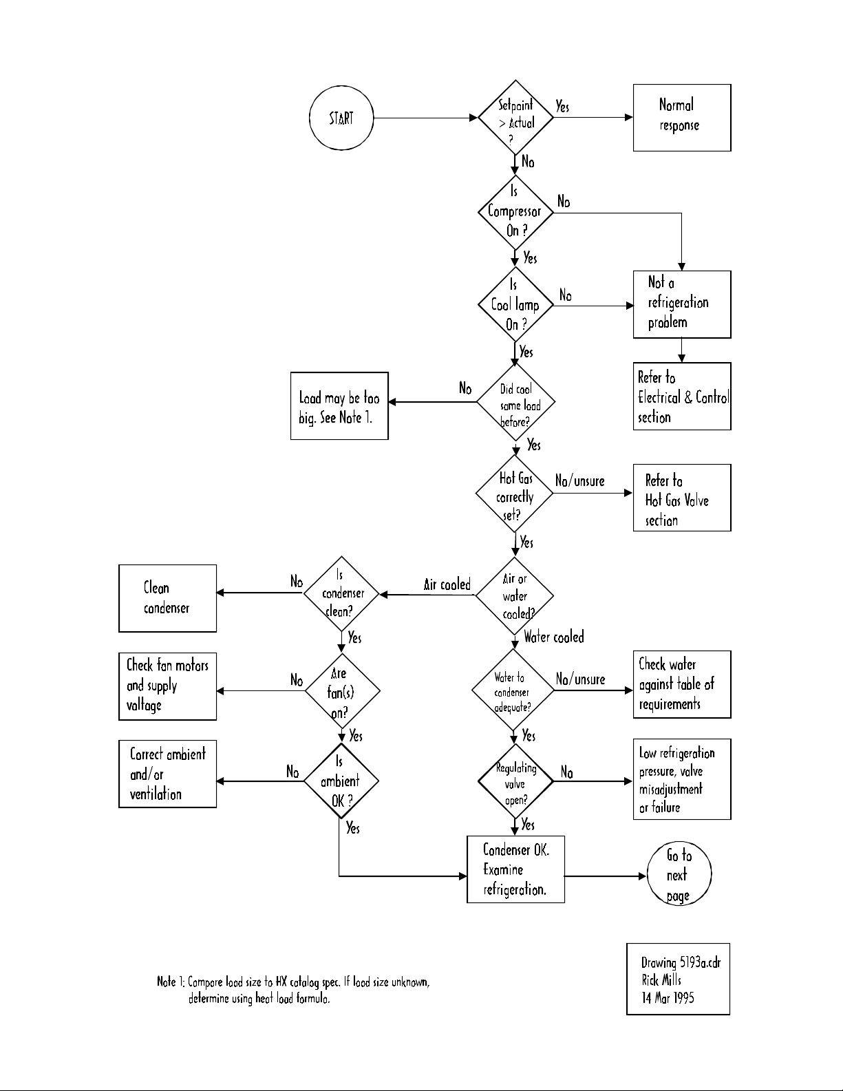
Troubleshooting Chart: Weak cooling ...................................................................... 8
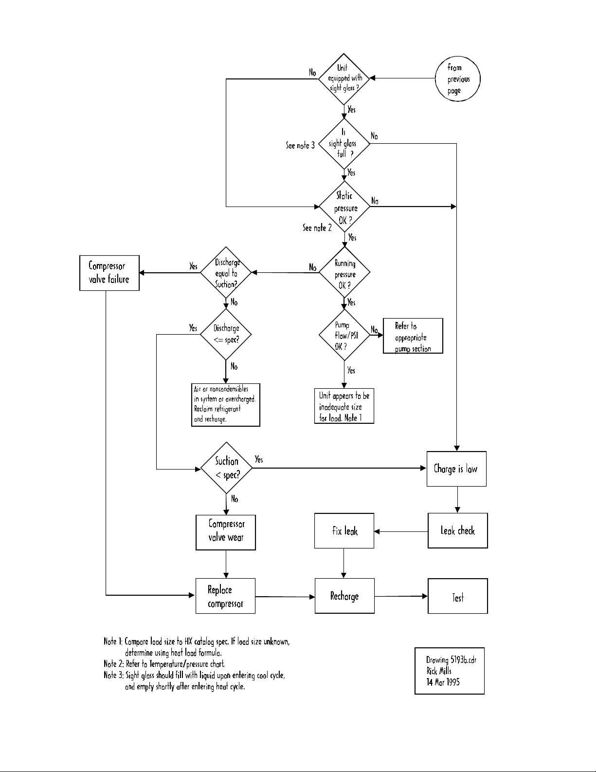
Troubleshooting Chart: Refrigeration pressures..................................................... 10
Replacement
Compressor............................................................................................................. 11
Fan Motor ................................................................................................................ 13
Filter/dryer ............................................................................................................... 14
Solenoid valve......................................................................................................... 15
Tank coil assembly (TCA) ....................................................................................... 17
Water regulating valve............................................................................................. 21
Capillary tube........................................................................................................... 23
Refrigeration components (general) ........................................................................ 25
Procedures
Speed check............................................................................................................ 27
Suction Discharge pressure and speed check ........................................................ 28
Condenser maintenance (air cooled & water cooled).............................................. 29
Flushing (closed facility system).............................................................................. 29
Flushing (tap water system) .................................................................................... 30
Flushing (unit off)..................................................................................................... 31
Commercial flushing chemicals ............................................................................... 32
Hot gas valve (Automatic Discharge Relief (ADR)) ................................................ 33
Schrader valves....................................................................................................... 37
Leak test and repair of leak ................................................................................ 38
Solenoid coil test ..................................................................................................... 39
Solenoid valve rebuild ............................................................................................. 40
Tank Coil Assembly (TCA) failure and repair ........................................................ 42

Water regulating valve setting ................................................................ 43
Reference
Refrigeration Specifications ................................................................... 44
R22 pressure-temperature chart ............................................................ 45
Heat load calculation .............................................................................. 46
Condenser re uirements: Air-cooled units ............................................ 47
Condenser re uirements: Water-cooled units ....................................... 48
15-pin accessory connector (optional) pinout ......................................... 49
Part numbers ......................................................................................... 50
3

4
This section is intended for use by qualified refrigeration techni-
cians only. Servicing refrigeration systems is hazardous and
must be performed only by qualified persons.
Refrigeration systems contain various hazards, including (but
not limited to) the following:
1. Refrigeration systems contain refrigerant gases at very high
pressures, even when not running.
2. Sudden release of refrigerant gases will result in rapid expan-
sion and severe frostbite hazard. Refrigerant gases will
cause severe injury to unprotected flesh.
3. Refrigerant gases are not flammable and are chemically
inert. However, they are heavier than air and will displace
oxygen. They can cause suffocation if released in a confined
area.
4. Refrigerant gases used in this product are classified as
Ozone Depleting Chemicals by the US Environmental Protec-
tion Agency. While they pose no hazard sealed inside the
refrigeration system, intentional release into the atmosphere
is outlawed under the 1990 Clean Air Act.
5. Compressor start and run capacitors store hazardous levels
of electricity, even when the unit is not running or plugged in.
6. Refrigeration system components operate at high tempera-
tures and present a severe burn hazard.
CAUTION

5
THEORY OF OPERATION
The chiller operates in two modes: COOL or HEAT/IDLE. The
controller compares setpoint to actual temperature and decides
which mode is required. This is a thermostatic (not proportional)
control system. The compressor, pump, and fan motor all run
continuously, regardless of mode.
The thermal transfer of the HEAT/IDLE mode is not as efficient
as the COOL mode. This results in units running at little or no
load to spend most of their time in the HEAT/IDLE mode with
brief periodic COOL periods. A duty cycle of 20% COOL / 80%
HEAT/IDLE may be typical for units running under no load. This
duty cycle will reverse as increasing load is applied, reaching
100% COOL / 0% HEAT/IDLE at full load.
This system results in tighter temperature control than continu-
ally cycling the compressor on and off, as is typical in a house-
hold refrigerator.
The default mode is HEAT/IDLE. A failure of the temperature
sensor or controller will generally result in the HEAT/IDLE
mode. This prevents a possible freezing of the cooling fluid and
resulting damage from fluid expansion.
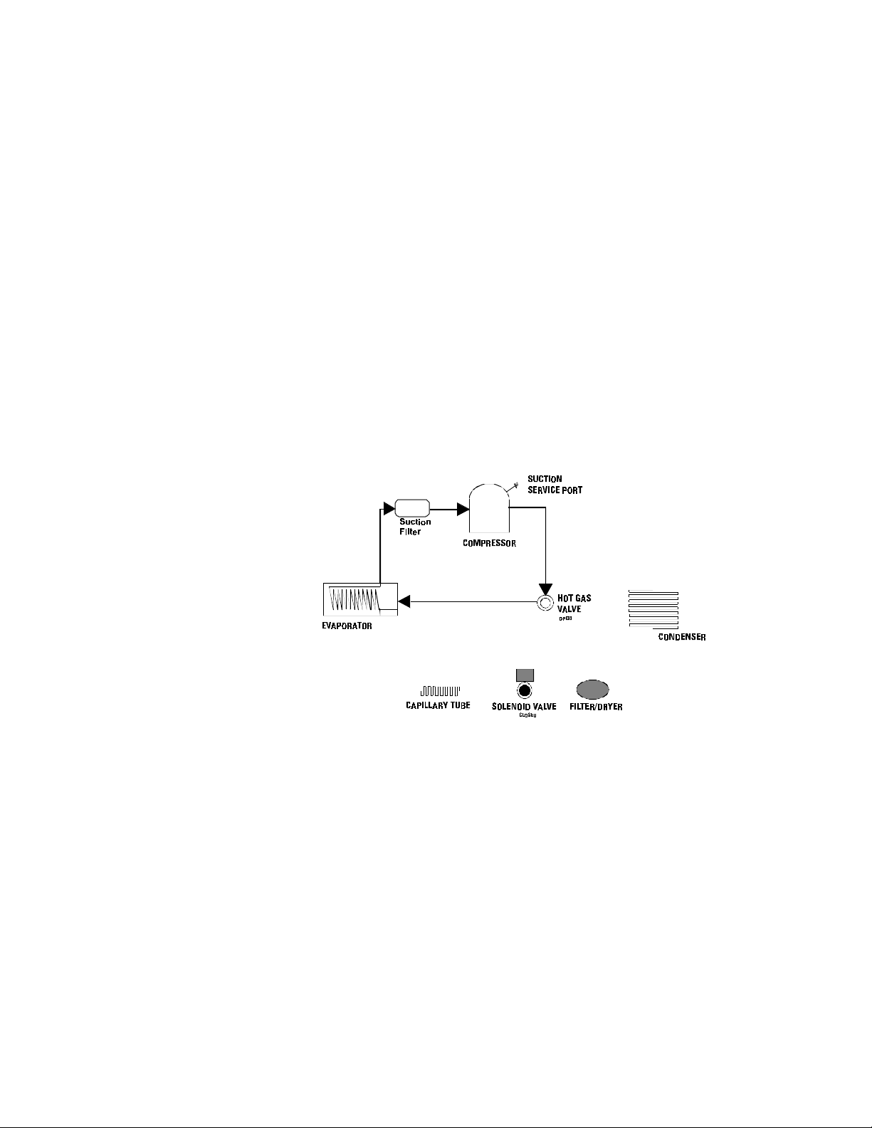
COOL MODE
If the setpoint is below the actual temperature, the controller is
in COOL mode. The controller triac output provides a closure
to supply line voltage to the solenoid coil. The solenoid valve,
which is normally-closed, is then pulled open by the coil and a
standard refrigeration cooling loop exists.
6
Refrigerant,asagas,ispressurizedinthe compressor.Itthen
enters the condenser and changes to a liquid due to the cooling
provided by the fan and condenser fins. Heat is given up to the
air at this point. The liquid refrigerant exits the condenser and
passes through a filter/dryer which traps contaminants and
absorbs any water moisture in its desiccant element. The refrig-
erant then passes through the open solenoid valve and enters
the capillary tube. The restriction of the tube meters the flow.
The capillary tube ends at the evaporator.
The evaporator is a coil located inside the fluid tank. As the
liquid refrigerant encounters the increased volume of the evapo-
rator, it expands tremendously, changing from a liquid to a gas,
and absorbing heat from the fluid (cooling it) in the process. The
refrigerant, now a gas, exits the evaporator and passes through
the suction filter. The refrigerant then enters the compressor at
low pressure and is re-compressed.
HEAT/IDLE MODE
If the setpoint is above the actual temperature, the controller is
inHEAT/IDLEmode. The triacoutputopens,turningthe solenoid coiloff.The
solenoidvalvethendropsclosed. This closed valve stops theflowofrefrigerant.
Duringthe heat/idle mode whentheliquidline solenoid valve isclosed,the
pressure drops in the suction line back to the compressor. When the pressure
dropstoa predetermined value, thehotgasbypassvalvewill open and allow
hotgas to flowtothe evaporator asstated.Thehot gas valveopenson a
decrease in pressure on its discharge port. The discharge port is connected to
theevaporator side ofthesystem.Therefrigerant gas isnowrouteddirectly to
the evaporator. The gas is not allowed to condense, as it has bypassed the
condensercompletely.Thehotgas passing through the evaporator
coil adds some heat to the fluid, then returns directly through the suction filter
tothe compressor.Thisunloads the compressor, resultinginlowerdischarge
pressure,highersuction pressure, and lesspowerconsumption.Observingthe
suction pressure in this mode will indicate the setting of the Hot Gas (ADR)
valve.

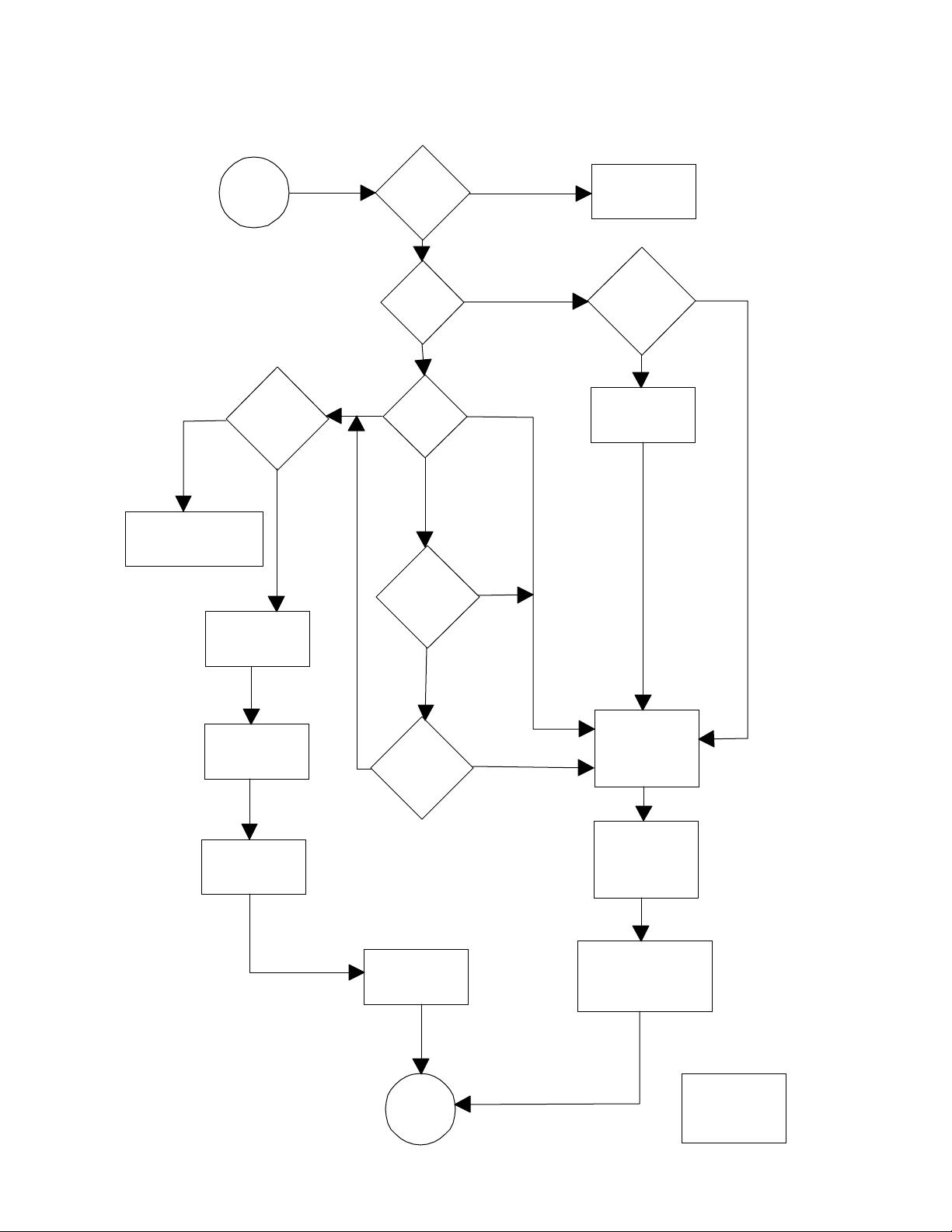
7
START
Is
Setpoint
< actual
?
Calibration
error
NO
YES
Replace
valve
Valve is
mechanically OK
Test
STOP
Refer to
ELECTRICAL & CONTROL
section
Remove coil
from valve
Drawing 67.cfl
Rick Mills
13 March 1995
YES
YES
NO
Valve is
stuck open
Not a
Refrigeration
Problem
Problem is in
Controller or
sensor
See VALVE
REPLACEMENT
Does
unit
warm up?
YES
NO
UNSURE
YESNO
NO
Can you
get cool
lamp off? *
Is
cool lamp
on?
* by manipulating setpoint
Is
coil
on?
Normal
Response
Troubleshooting Chart: Runaway cold
8
START
Is
Setpoint
> actual
?
Normal
response
Calibration
Error
NO
YES
Replace
valve
Test
STOP
Refer to
ELECTRICAL & CONTROL
section
Drawing 68.cfl
Rick Mills
13 March 1995
YES
NO
Valve is
stuck closed
Not a
refrigeration
problem
See VALVE
REPLACEMENT
UNSURE
Can you
get cool
lamp on? *
Is
cool lamp
on?
YES
NO
NO
YES
NO YES
NO
YES
NO
YES
*by manipulating setpoint
See TROUBLESHOOTING:
"WEAK COOLING"
Any
DC volts
on coil
?
Any
AC volts
on coil
?
Is
coil
on?
Problem is in
Controller or
Sensor
Is it
cooling
at all ?
Troubleshooting Chart: Runaway hot
9
Troubleshooting Chart: Weak cooling
10
Troubleshooting Chart: Weak cooling continued

11
Troubleshooting Chart: Refrigeration pressures
12
Compressor replacement
1. Remove all access panels.
2. Confirm that the problem is not external to the compressor
(electrical) before proceeding. If the compressor does not
start/run, check the following:
A. Is proper voltage present at the
compressor terminals?
B. Are all starting devices (capacitors,
potential relays) good?
Disconnect the unit from line voltage
C. Are the motor windings known to be
good or bad? If in doubt, Ohmmeter
readings of the windings may be compared
to the replacement compressor.
3. Recover the system refrigerant.
4. Disconnect wires, starting devices, etc. from compressor.
5. Remove valve cores from both Shrader valves.
6. Remove the coil from the solenoid valve and move it out of
the torch area. Wrap a damp rag around the solenoid valve
body.
7. Unsolder and remove compressor and dryer.
NOTE: If a compressor burnout is suspected, invert old
compressor and drain out a small sample of oil. Test the oil
for acidity, following the manufacturer’s recommendations on
the acid test kit. If the oil is acidic, the refrigeration system will
need flushing to remove the acidic oil. Replace with new oil.

13
8. Unpack new compressor. Remove plugs from the ports.
Compressors are typically shipped pressurized with a
dry nitrogen charge. Safety glasses are especially
necessary when removing plugs. Orient compressor so
the plug will exit the port pointing away from you and
others.
NOTE: Replacement Copeland compressors already con-
tain an adequate oil charge. It is not necessary to add any
oil to the new compressor.
9. Remove the suction service port stem from the old com-
pressor, and insert it into the new compressor.
10. Apply nitrogen purge gas to the stem.
11. Braze in place using BAg 28 (silver solder) compound.
12. Position the new compressor in place.
13. Position the new dryer in place. Ensure the flow direction
arrow points toward the solenoid valve.
14. Wrap a damp rag around the dryer.
15. Apply nitrogen purge gas to the suction service port.
16. Braze the suction and discharge lines to the compressor,
using BAg 28.
17. Braze the dryer in place, using BAg 28.
18. Insert new valve cores in the Shrader valves.
19. Pressurize system and leak check.
20. Evacuate system.
21. Charge system to specification.
22. Test system.

14
Fan Motor Replacement
1. Disconnect unit from its electrical power supply.
2. Note the location and orientation of the electrical wiring for
installation.
3. Disconnect the electrical wiring.
4. Unbolt the fan from the base of the condensing unit.
5. Pull the fan assembly (motor, blade, and bracket) out of the
unit.
6. Transfer the blade, conduit, and/or bracket to the new motor.
7. Reassemble in reverse order.

15
FILTER/DRYER REPLACEMENT
NOTE: The filter/dryer contains a desiccant which will absorb
moisture from the atmosphere. The filter/dryer should be
replaced whenever the refrigeration system has been opened
and allowed to go to atmospheric pressure. Unsealing and
installing the new filter/dryer should be left until the last pos-
sible minute to minimize contamination of its
desiccant.
Disconnect the unit from line voltage
1. Recover the system refrigerant.
2. Remove all Shrader valve cores.
3. Remove solenoid valve internal components (See “Solenoid
valve replacement procedure” for drawing) Wrap a damp rag
around the solenoid valve body.
4. Apply purge gas to the system.
5. Desolder and remove old filter/dryer.
6. Place new filter/dryer in position, with direction-of-flow arrow
pointing towards the liquid line solenoid valve.
7. Wrap the filter/dryer body in a damp rag.
8. Introduce nitrogen purge gas into the discharge service port.
9. Braze connections using BAg 28. Orient torch flame away
from the filter/dryer body. Any bubbling of the paint on the
filter/dryer indicates excessive temperature is being ap-
proached - stop and allow to cool if this occurs.
10. Remove the damp rags and the nitrogen supply.
11. Insert new schrader valve cores.
12. Assemble the solenoid valve (Do Not over tighten - Use two
wrenches).
11. Pressurize and leak check.
12. Evacuate system.
13. Charge system.
14. Test.
15. Install any access panels removed.

16
Solenoid valve replacement:
Disconnect the unit from line voltage
1. Recover refrigerant.
2. Remove coil.
3. Remove all valve cores from the Shrader valves.
4. Note the direction of flow so that the new valve can be prop-
erly positioned during assembly. Disassemble solenoid valve
and remove internal components as shown below.

17
5. Protect all components that could be affected by the solder-
ing flame with damp rags and metal shielding.
6. Apply a nitrogen purge gas to the system.
7. Unsolder the valve and dryer and remove.
8. Place new valve and dryer in position. Check that the flow
direction arrows on both devices point towards the capillary
tube.
9. Wrap a damp rag around the valve and dryer and protect any
other components/wiring with damp rags and metal shields.
10. Apply nitrogen purge gas to the system.
11. Braze in place using BAg 28 compound (silver solder).
12. Remove rags and inspect brazing.
13. Install new valve cores in the Shrader valves.
14. Assemble solenoid valve assembly. (Use two wrenches and
do not over tighten.)
15. Pressurize system and leak check. The solenoid valve is
closed, so be sure to pressurize both sides.
12. Evacuate the refrigeration system.
13. Install coil.
14. Charge system to specification.
15. Test system.
16. Install any access panels removed.

18
NOTE: The evaporator coil and the water tank are one unit.
They cannot be separated. The following procedure assumes
that the pump along with its plumbing has been removed.
Disconnect unit from line voltage.
1. Recover refrigerant, if any remains.
2. Drain fluid from system.
3. Remove valve cores from both Shrader valves.
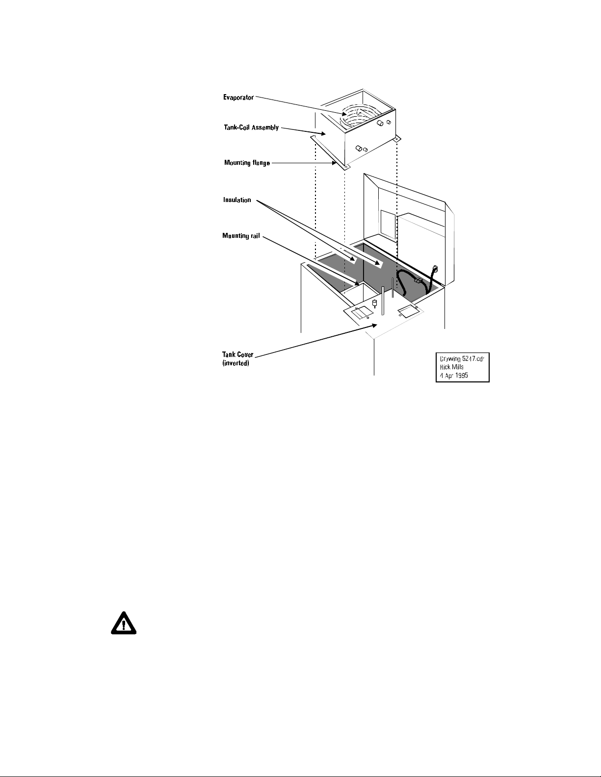
Tank Coil Assembly (TCA) replacement

19
4. Remove screws from Tank Cover and lift it off the tank with
all wires, motors, sensors, etc. intact. Invert it and place it to
the side as shown. If more slack is required in the wires,
unplug the connector shown.
5. Remove the two fluid hoses from the water inlet and outlet
stubs.
6. Remove the insulation from the refrigerant inlet and outlet
lines.
7. Unsolder the refrigerant inlet and outlet lines.
CAUTION: The refrigerant inlet and outlet lines are stain-
less steel. They are easily damaged by excessive heat.
Never apply the torch flame directly to the stainless. Warm
the copper fittings up slowly and evenly until the solder
liquefies.
8. Remove the four screws that hold the TCA mounting flange
to the mounting rails.
20
9. Lift the TCA straight up out of the unit.
10. Inspect the insulation on the inside of the case walls while the
TCA is removed. Replace any that is wet. Install insulation
on the new TCA.
11. Transfer the strainer from inside the old TCA to the new TCA,
if required.
12. Clean the refrigeration stubs on the new TCA carefully prior
to installation. Clean the inside of the mating copper lines
prior to installation.
13. Lower the TCA into place and secure the mounting flange to
the mounting rails.
CAUTION: The refrigerant inlet and outlet lines are stain-
less steel. They are easily damaged by excessive heat.
Solder the fittings as follows:
A. Ensure all fittings have been carefully cleaned.
B. Apply a paste-type flux.
Table of contents
Other Thermo Chiller manuals


Popular Chiller manuals by other brands


Elkay
Elkay ECP8 1H Series Installation, care & use manual

Carrier
Carrier Flotronic 30GB user manual

Carrier
Carrier ECOLOGIC 30GXN installation instructions

SMC Networks
SMC Networks HRS018-A*-20-* Operation manual

Carrier
Carrier AQUASNAP 30RB060-390 Controls, start-up, operation, service and troubleshooting instructions

Cres Cor
Cres Cor CCBC-12-75 Installation, operation & service manual


