Thermo CFT-25 Manual

NESLAB CFT Series
Recirculating Chiller
Thermo Manual P/N U00362
Rev. 08/18/99
Instruction and Operation Manual
No part of this publication may be repro-
duced or reprinted except for personal use
without the prior permission of Thermo
Electron.

- 1 -
NESLAB CFT Series Recirculating Chiller
PREFACE
Compliance ............................................................................................ 3
Unpacking .............................................................................................. 3
Warranty ................................................................................................. 3
NES-care ................................................................................................ 3
After-sale Support ................................................................................... 3
SECTION I
Safety
Warnings ................................................................................................ 4
Additional Warnings ...............................................................................
SECTION II
General Information
Description ............................................................................................. 6
Specifications ......................................................................................... 6
Cooling Capacity .................................................................................... 8
Pump Capacity ....................................................................................... 8
SECTION III
Installation
Site ......................................................................................................... 9
Electrical Requirements ......................................................................... 10
Plumbing Requirements ......................................................................... 10
Fluids ..................................................................................................... 11
Water Quality Standards and Recommendations ................................... 12
Filling Requirements ............................................................................... 13
SECTION IV
Operation
Start Up .................................................................................................. 1
Temperature Controller .......................................................................... 16
Temperature Limits ................................................................................ 17
Pressure Relief Valve............................................................................. 17
High/Low Pressure Cutouts.................................................................... 17
High Temperature Cutout (Optional) ...................................................... 18
Heater Package (Optional) ..................................................................... 18
External Pressure Reducer (Optional) .................................................... 19
SECTION V
Maintenance & Service
Service Contracts ................................................................................... 20
Draining the Reservoir ........................................................................... 20
Cleaning ................................................................................................. 20
Algae ...................................................................................................... 21
Pump Strainer ........................................................................................ 21
Pump Lubrication ................................................................................... 22
Hoses..................................................................................................... 22
Suction Discharge Pressure/Speed Check ............................................ 22
Error Codes ............................................................................................ 23
Displaying Software Version ................................................................... 23
CFT-300 Fuses ....................................................................................... 24
Pump Flow Diagram ............................................................................... 24
SECTION VI
Tro bleshooting
Checklist ................................................................................................ 2
Service Assistance ................................................................................. 2
WARRANTY

- 2 -
CFT Series Q ick Reference Operating Proced res
When the unit is shut off, wait approximately five
minutes before restarting. This allows time for the
refrigeration pressures to equalize. If the pressures
are not allowed to equalize, the compressor will
short-cycle and no cooling will occur.
Temperature Adjustment
To display the temperature setpoint, press the
NEXT ENTER button on the controller. To adjust
the temperature setpoint, press the YES or NO key
until the desired temperature setpoint is indicated.
Once the setpoint is adjusted, press NEXT EN-
TER. The display will now indicate the temperature
of the fluid in the reservoir.
Periodic Maintenance
Periodically inspect the reservoir fluid. If cleaning is
necessary, flush the reservoir with a cleaning fluid
compatible with the circulating system and the
cooling fluid.
The cooling fluid should be replaced periodically.
When operating at low temperatures, the concen-
tration of water in the cooling fluid will increase
over time, leading to a loss of cooling capacity.
Before changing the cooling fluid, raise the unit's
operating temperature to de-ice the cooling coils.
Periodic vacuuming of the condenser fins is
necessary. The frequency of cleaning depends on
the operating environment. We recommend a
visual inspection of the condenser be made
monthly after initial installation. After several
months, the cleaning frequency will be established.
Units with PD pumps have a strainer. If debris is in
the system, the strainer will prevent the material
from being drawn into the pump and damaging the
pump vanes.
After initial installation, the strainer may become
clogged. Clean the strainer after the first week of
installation. After this first cleaning, we recommend
a monthly visual inspection. After several months,
the cleaning frequency will be established. Before
cleaning, disconnect the power cord from the
power source and drain the reservoir.
Installation
The unit has an air-cooled refrigeration system. Air
is drawn in the front of the unit and discharged
through rear and side. Position the unit so the
intake and discharge are not impeded. Inadequate
ventilation will cause a reduction in cooling capac-
ity and, in extreme cases, compressor failure.
Excessively dusty areas should be avoided and a
periodic cleaning schedule should be instituted.
For proper operation, the unit needs to pull sub-
stantial amounts of air through a condenser. A
build up of dust or debris on the fins of the con-
denser will lead to a loss of cooling capacity.
The unit will retain its full rated capacity in ambient
temperatures up to approximately +24°C.
Make sure the voltage of the power source meets
the specified voltage, ±10%.
The plumbing connections are located on the rear
of the unit and are labelled either SUPPLY and
RETURN or OUTLET and INLET. These connec-
tions are ½ inch FPT, ¾ inch FPT for CFT-1 0s
with CP- pumps and CFT-300s. Remove the
plastic protective plugs from both plumbing con-
nections. Connect the OUTLET/SUPPLY fitting to
the inlet of the instrument being cooled. Connect
the INLET/RETURN fitting to the outlet of the
instrument being cooled.
To fill the reservoir, remove the reservoir access
panel by unscrewing the thumbscrews. Locate the
reservoir plug (square nut). Remove the plug and
fill the reservoir with clean cooling fluid.
We recommend using distilled/deionized water with
a 0.0 to 0.1 megohm-cm reading.
If you do not have access to distilled/deionized
water we recommend using filtered tap water.
Operation
Before starting the unit, double-check all electrical
and plumbing connections. Make sure the circulat-
ing system has been filled with cooling fluid.
To start the unit, place the Power Switch to the on
position. The Power Switch illuminates (except for
the CFT-1 0) to indicate the system is operating.
To turn the unit off, place the Power Switch to the
off position.
The Cool LED indicates the status of the refrigera-
tion system. It illuminates to indicate the refrigera-
tion system is removing heat from the cooling fluid.
As the operating temperature approaches the
setpoint, the LED will flash.

- 3 -
Preface
Compliance
Products tested and found to be in compliance with the requirements defined in the
EMC standards defined by 89/336/EEC as well as Low Voltage Directive (LVD) 73/
23/EEC can be identified by the CE label on the rear of the unit. The testing has
demonstrated compliance with the following directives:
LVD, 73/23/EEC Complies with UL 3101-1:93
EMC, 89/336/EEC EN 011, Class A Verification
EN 0082-1:1992
IEC 1000-4-2:199
IEC 1000-4-3:1994
IEC 1000-4-4:199
For any additional information refer to the Letter of Compliance that shipped with
the unit (Declaration of Conformity).
Unpacking
Retain all cartons and packing material until the unit is operated and found to be in
good condition. If the unit shows external or internal damage contact the transpor-
tation company and file a damage claim. Under ICC regulations, this is your
responsibility.
When unpacking the unit, we recommends using a hoist. Units are not equipped
with handles. Roll the unit on its casters to move it.
If this product has been modified to operate at 0°C or lower, it has been tested with
a non-freezing fluid. Although the system has been drained, some residual fluid
may remain. This will not hinder your unit's performance.
Warranty
Units have a warranty against defective parts and workmanship for one full year
from date of shipment. See back page for more details.
NES-care Extended
Warranty Contract
Extend parts and labor coverage for an additional year.
Worry-free operation.
Control service costs.
Eliminate the need to generate repair orders.
No unexpected repair costs.
Other contract options are available. Please contact us for more information.
After-sale S pport
Thermo Electron Corporation is committed to customer service both during and
after the sale. If you have questions concerning the unit operation, contact our
Sales Department. If your unit fails to operate properly, or if you have questions
concerning spare parts or Service Contracts, contact our Service Department.
Before calling, please refer to the labels on the rear of the unit to obtain the follow-
ing information:
- unit BOM number_________________________________
- unit serial number ________________________________
- software version (see page 23)_______________________

- 4 -
Section I Safety
Warnings
Warnings are posted throughout the manual. These warnings are desig-
nated by an exclamation mark inside an equilateral triangle and text high-
lighted in bold. Read and follow these important instructions. Failure to
observe these instructions can result in permanent damage to the unit,
significant property damage, or personal injury or death.
Make sure you read and understand all instructions and safety precautions
listed in this manual before installing or operating your unit. If you have any
questions concerning the operation of your unit or the information in this
manual, please contact our Sales Department (see After-sale Support).
Never place the unit in a location where excessive heat, moisture, or
corrosive materials are present.
The unit construction provides protection against the risk o electrical
shock by grounding appropriate metal parts. The protection may not
unction unless the power cord is connected to a properly grounded
outlet. It is the user's responsibility to assure a proper ground connec-
tion is provided.
Never connect the OUTLET/SUPPLY or INLET/RETURN itting to your
building water supply or any water pressure source.
Never use lammable or corrosive luids with this unit. Distilled and
deionized water may be aggressive and cause material corrosion.
Please contact us be ore subjecting this unit to prolonged exposure to
distilled or deionized water.
Do not use automobile anti- reeze. Commercial anti- reeze contains
silicates that can damage the pump seals. Use o automobile anti-
reeze will void the manu acturers warranty.
Do not replace reservoir plug with a non-vented type or damage to the
tank may occur.

- -
Additional Warnings
In addition to the specific warnings listed on the previous page the following
general warnings apply to you unit:
Per ormance o installation, operation, or maintenance procedures
other than those described in this manual may result in a hazardous
situation and may void the manu acturer's warranty.
Transport the unit with care. Sudden jolts or drops can damage the
re rigeration lines.
Observe all warning labels.
Never remove warning labels.
Never operate damaged or leaking equipment.
Never operate the unit without cooling luid in the reservoir.
Always turn o the unit and disconnect the power cord rom the power
source be ore per orming any service or maintenance procedures, or
be ore moving the unit.
Always empty the reservoir be ore moving the unit.
Never operate equipment with damaged power cords.
Re er service and repairs to a quali ied technician.

- 6 -
Section II General Information
Description
The NESLAB CFT Recirculating Chiller is designed to provide a continuous
supply of cooling fluid at a constant temperature and volume.The unit consists
of an air-cooled refrigeration system, a sealable reservoir, recirculating pump,
and a temperature controller.
Throughout the manual, you will be asked to consult the units serial number
label or the pump identification label for specific information. Both labels are
located on the rear of the unit.
1. 60 Hertz CFT-75s with a "Turbulator" tank have a 2500 watt coolin capacity.
2. Circulatin water at 20°C, at 20°C ambient. Coolin capacity will vary dependin on fluid
temperature, ambient temperature, and coolin fluid. A PD-1 pump was used in the CFT-25, a
PD-2 in the other units.
3. Modified temperature ran es from -15°C to +85°C are available.
4. CFT-300 stability determined with 86% heat load.
5. 1.25 allons (4.73 liters) for 50 Hertz CFT-75 units.
1.8
6.8
CFT-25 CFT-33 CFT-75 CFT-150 CFT-300
±1.0°C
1.1
4.2
.6
21.3
R22R134a
+ °C to +30°C + °C to +3 °C
±0. °
Specifications
Cooling Capacity1,2
Temperature Range3
Temperature Stability4
Reservoir Volume5
Gallons
Liters
Re rigerant
Pollution Degree
12
8
4
5
4
3
2
1
HEAT REMOVAL (KILOWATTS)
0 5 10 15 20 25 30
TEMPERATURE (°C)
C=CFT-150, 60HZ
D=CFT-150, 50HZ
E=CFT-75, 60HZ
F=CFT-75, 50HZ
G=CFT-33, 60HZ
H=CFT-33, 50HZ
I=CFT-25, 60HZ
J=CFT-25, 50HZ
A=CFT-300, 60HZ
B=CFT-300, 50HZ
A
B
C
D
E
F
G
H
I
J
II, IAW IEC 664
0.4
1.4

- 7 -
C
A
B
H
E
Plug
1. Dimension A is the height of the unit. The unit width and depth (dimensions B and C) are the case dimensions, add
approximately inches to include the plumbing connections. The depth case dimension for CFT-75s with "Turbulator"
tanks is 5¾".
. Dimension D is the distance from the floor to the bottom of the unit case (height of the castors).
3. Dimension E is the distance from the floor to the center of the DRAIN connection (CFT-150/300 only).
4. Dimension F is the distance from the floor of the center of the OUTLET connection.
5. Dimension G is the distance from the floor of the center of the INLET connection.
6. Dimension H is the distance from the unit's left side to the center of the INLET and OUTLET connections.
7. Dimension I is the distance from the unit's left side to the center of the DRAIN connection (CFT-150/300 only).
8. Weights are given in pounds
9. Air intake is given in cubic feet per minute.
Unit Dimensions
Dimension A
Dimension B
Dimension C
Dimension D
Dimension E
Dimension F
Dimension G
Dimension H
Dimension I
Crate Dimensions
(H x W x D)
Shippin Wei ht
Air Intake
Electrical Requirements
Volts
Hertz
Phase
CFT25 CFT33 CFT75 CFT150 CFT300
22 24½ 26½ 36¾ 43
12½ 14¾ 14 7/8213/825½
21 22 24½ 27¾ 27¾
2¾ 2½ 2½ 3½ 2¾
NA NA NA 23½ 29
171/16 18½ 22 32¼ 38¼
201/16 21½ 25 35¼ 41¼
1½ 1 11/811/81
NA NA NA 6 1
31x23x28 31x23x32 32x23x40 33x29x42 35x33x56
132 160 215 311 450
280 375 800 1050 2500
115V 115V 208/230V 208/230V 208/230V
60Hz 60Hz 60Hz 60Hz 60Hz
11113
NEMA5-15P NEMA5-20P NEMAL6-15P NEMAL6-20P NA
D
F
G
Rev 04/12/99
I

- 8 -
10
8
6
4
2
A
B
Flow
Pressure
0.7
0.5
0.4
0.3
0.1
Bar PSI
4.0
3.4
2.7
2.0
1.3
0.7
B
Pressure
60
50
40
30
20
10
Bar PSI
1 2 3 4 GPM
3.8 7.5 11.3 15.1 LPM
Flow
P mp Capacity
1 2 3 4 5 GPM
3.8 7.5 11.3 15.1 19.0 LPM
A=PD-1 60Hz
B=PD-1 50Hz
C=PD-2 60Hz
D=PD-2 50Hz
AC
D
A=MD-30 60Hz
B=MD-30 50Hz
A=CP-55 60Hz
B=CP-55 50Hz
3.4
2.7
2.0
1.3
0.7
B
Pressure
50
40
30
20
10
Bar PSI
A
Flow
5 10 15 20 25 30 GPM
18.9 37.9 56.8 75.5 94.6 113.6 LPM

- 9 -
Section III Installation
Site
The unit should be located in a laboratory or clean industrial environment
where ambient temperatures are inside the range of +13°C to +3 °C, and
maximum humidity is below 80%.
Never place the unit in a location where excessive heat, moisture, or
corrosive materials are present.
The unit has an air-cooled refrigeration system. Air is drawn through the
front of the unit and discharged through rear and side panels. The unit must
be positioned so the intake and discharge are not impeded. A minimum
clearance of 18 inches (4 centimeters) on all vented sides is necessary for
adequate ventilation. Inadequate ventilation will cause a reduction in cooling
capacity and, in extreme cases, compressor failure.
Excessively dusty areas should be avoided and a periodic cleaning schedule
should be instituted (see Section V, Cleaning).
The unit will retain its full rated capacity at ambient temperatures up to approxi-
mately +24°C. Above +24°C, reduce the cooling capacity 1% for every 0. °C
above +24°C, up to a maximum ambient temperature of +3 °C.
Direction of Air Flow

- 10 -
Electrical
Req irements
The unit construction provides protection against the risk o electrical
shock by grounding appropriate metal parts. The protection may not
unction unless the power cord is connected to a properly grounded
outlet. It is the user's responsibility to assure a proper ground connec-
tion is provided.
Refer to Section II, Specifications, and to the serial number label on the rear of
the unit for the specific electrical requirements of your unit. Ensure the voltage
of the power source meets the specified voltage, ±10%. Transient overvolt-
ages must comply with OVERVOLTAGE CATEGORY II. For mains supply,
the minimum and normal category is II.
The CFT-300 is supplied with a junction box located behind the controller
panel. Wire the power connections in accordance to local, state and federal
electrical codes. Double check all wiring to make sure it is properly connected
and protected from the elements.
The CFT-300 is also equipped with a compressor crankcase heater. The
crankcase heater warms the oil in the compressor and prevents refrigerant
from mixing with the oil. Before start up, the unit must be connected to its
power source for at least 12 hours. This allows time for the oil to be heated and
separate from the refrigerant.
Pl mbing
Req irements
Before installing the unit to an instrument that
previously used tap water as a cooling fluid,
flush the instrument several times to remove
any rust or scale that has built up. The manu-
facturer of the instrument should be able to
recommend a cleaning fluid for their equipment.
The plumbing connections are located on the
rear of the unit and are labelled OUTLET/
SUPPLY and INLET/RETURN. CFT-2 to CFT-
1 0 connections are ½ inch FPT,
CFT-1 0s with CP- pumps are ¾ inch and
CFT-300 connections are ¾ inch FPT.
Remove the plastic protective plugs from both plumbing connections.
Connect the OUTLET/SUPPLY fitting to the inlet of the instrument being
cooled. Connect the INLET/RETURN fitting to the outlet of the instrument
being cooled.
Never connect the ittings to your building water supply or any water
pressure source.
Two sets of plumbing adapters are included with CFT-2 to CFT-1 0 units. One
set of adapters will accept 3/8 inch ID tubing. The other set will accept
- 11 -
½ inch ID tubing. If the unit is being plumbed using flexible tubing, install one
set of adapters in the plumbing ports. To prevent leaking, be sure to wrap the
threads of the adapters with Teflon® sealing tape before installing them in the
plumbing ports.
Flexible tubing, if used, should be of heavy wall or reinforced construction. All
tubing should be rated to withstand 80 psig at the highest operating tempera-
tures. Make sure all tubing connections are securely clamped. Avoid running
tubing near radiators, hot water pipes, etc. If substantial lengths of tubing are
necessary, insulation may be required to prevent loss of cooling capacity.
Tubing and insulation are available. Contact our Sales Department for more
information (see Preface, After-sale Support).
It is important to keep the distance between the unit and the instrument
being cooled as short as possible, and to use the largest diameter tubing
practical. Tubing should be straight and without bends. If diameter reductions
must be made, they should be made at the inlet and outlet of the
instrument being cooled, not at the CFT.
If substantial lengths of cooling lines are required, they should be pre-filled
with cooling fluid before connecting them to the unit.
Fl ids
Never use lammable or corrosive luids with this unit. Do not use
automotive anti- reeze. Commercial anti- reeze contains silicates that
can damage the pump seals. Use o automotive anti- reeze will void the
manu acturers warranty.
We recommends using distilled/deionized water with a 0.0 to 0.1 megohm-cm
reading.
Highly distilled/deionized water, above the 3 megohm-cm region, may
become aggressive and is not recommended or use with units with
wetted parts other than stainless steel. Distilled/deionized water in the
15 megohm-cm region is de initely aggressive and should not be used.
Units operating in these regions should be closely monitored. See
Water Quality Standards and Recommendations in this section.
If you do not have access to distilled/deionized water we recommend using
filtered tap water. We cannot recommend any custom fluids; these fluids are
too dependent on your particular application.
Below +8°C, a non-freezing solution is required. The selected cooling fluid
must have a viscosity of 0 centistokes or less. A 0/ 0 mixture, by volume,
of distilled/deionized water and laboratory grade ethylene glycol is suggested.
For units with extended temperature ranges above +3 °C, we recommend
distilled/deionized water up to +80°C. Above +80°C, you are responsible for the
fluid(s) used.

- 12 -
Water Q ality Standards
and Recommendations
Permissible (PPM) Desirable (PPM)
Microbiologicals
(algae, bacteria, fungi) 0 0
Inorganic Chemicals
Calcium <40 <0.6
Chloride <2 0 <2
Copper <1.3 <1.0
Iron <0.3 <0.1
Lead <0.01 0
Magnesium <12 <0.1
Manganese < 0.0 <0.03
Nitrates\Nitrites <10 as N 0
Potassium <20 <0.3
Silicate <2 <1.0
Sodium <20 < 0.3
Sulfate <2 0 < 0
Hardness <17 <0.0
Total Dissolved Solids < 0 <10
Other Parameters
pH 6. -8. 7-8
Resistivity 0.01* 0.0 -0.1*
* Megohm-Cm (Compensated to 2 °C)
Unfavorably high total ionized solids (TIS) can
accelerate the rate of galvanic corrosion. These
contaminants can function as electrolytes which
increase the potential for galvanic cell corrosion and
lead to localized corrosion such as pitting which can
be observed at the studs and on the outside surface
of cooling coils. Eventually, the pitting will become
so extensive that the coil will leak refrigerant into the
water reservoir.
As an example, raw water in the United States
averages 171 ppm (of NaCl). The recommended
level for use in a water system is between 0. to .0
ppm (of NaCl).
Recommendation: Initially fill the tank with distilled/
deionized water. Do not use untreated tap water as
the total ionized solids level may be too high.
Maintain this water quality at a resistivity of between
1 to 10 megohm-cm (compensated to 2 °C) by
using a purification system. Although the initial fill
may be as high as 10 megohm-cm (compensated to
2 °C), the desired level for long time usage is 1 to 3
megohm-cm (compensated to 2 °C).
The above two recommendations will reduce the
electrolytic potential of the water and prevent or
reduce the galvanic corrosion observed.
15.00
10.00
3.00
1.00
0.10
0.05
Resistivity (me ohm-cm @ 25°C)
Not Recommended, Increasin ly Corrosive
Operations with Stainless Steel Systems
Operations with
Mixed Metals
Copper/Brass/
Stainless Steel
CONS LT MATERIALS ENGINEER
10 20 30 40 50 60 70 80
Water Quality Considerations
°C
- 13 -
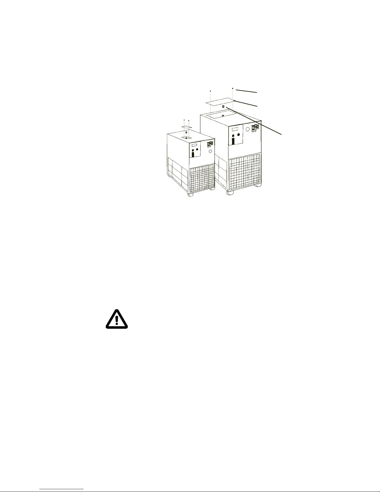
Reservoir fillin locations (Typical)
Thumbscrew
Filling Req irements
Remove the reservoir access panel by unscrewing the thumbscrews. Locate
the reservoir plug (square nut). Remove the plug and fill the reservoir with
clean cooling fluid, following the special considerations outlined in the
following paragraphs.
Circulating to a closed system (closed to the atmosphere)
|Fill the reservoir to the bottom of the fill hole threads. Since the reservoir
capacity is small compared to many instruments being cooled, have extra
cooling fluid on hand to keep the system topped off when external circulation
is started.
NOTE: The tank in your unit has a vent that relieves pressure built up from
thermal expansion of water. The vent is located on the reservoir plug. It
activates when tank pressure reaches 3 - psi.
Do not replace reservoir plug with a non-vented type or damage to the
tank may occur.
Circulating to an open system (open to the atmosphere)
Fill the reservoir so ¾ of the fill hole threads are covered. Wrap the tank
plug with Teflon® sealing tape. Replace the tank plug and tighten securely to
prevent air entry.
When circulating cooling fluid to an open vessel or tank, connect the OUTLET/
SUPPLY and INLET/RETURN lines to the open tank. Secure the INLET/
RETURN (suction) line below the fluid surface. The INLET/RETURN line should
be submerged deep enough to avoid sucking air. Make sure the INLET/
RETURN line is free of particles and debris that can block the flow of fluid. A
baffle or screen may be required.
Reservoir Access Panel
Reservoir Plug

- 14 -
Blank page.

- 1 -
Section IV Operation
Start Up
Before starting the unit, double check all electrical and plumbing connections
and make sure the circulating system (the CFT, the instrument being cooled,
and the tubing that connects them) has been properly filled with cooling fluid.
On units with a circuit breaker located on the rear of the unit, ensure it is the
on position. To start the unit, place the POWER Switch to the on ( I ) position.
The refrigeration system and the recirculation pump will start. The POWER
Switch illuminates (except for the CFT-1 0) to indicate the system is operat-
ing. Units with PD pumps display the pump operating pressure on the RECIR-
CULATING PRESSURE gauge.
To turn the unit off, place the POWER Switch to the off ( 0 ) position.
COOL indicates the status of the refrigeration system. It illuminates to indi-
cate the refrigeration system is removing heat from the cooling fluid. As the
operating temperature approaches the temperature setpoint, the LED will
flash. IDLE indicates the unit is in a hot-gas-bypass mode of operation. As the
operating temperature approaches the temperature setpoint, the LED extin-
guishes.
When the unit is shut off, wait approximately five minutes before restarting.
This allows time for the refrigeration pressures to equalize. If the pressures
are not allowed to equalize, the compressor will short-cycle (clicking sound)
and no cooling will occur.
Di ital Temperature Controller
COOL
IDLE
YES
NO
NEXT
ENTER
°C

- 16 -
Digital Controller
The digital controller controls temperature using a PID (Proportional-Integral-
Derivative) algorithm. It is designed with self-diagnostic features and easy to
use operator interface.
NEXT ENTER
Use this key to accept and save changes.
YES,
This key is used to increase numerical values.
NO,
This key is used to decrease numerical values.
When the controller is powered it displays the reservoir fluid temperature.
Press the NEXT ENTER key to view the setpoint. The display flashes be-
tween SP and the actual setpoint number. If desired, use the YES and NO
keys to change the setpoint. The display flashes as soon as either key is
depressed. Once the desired setpoint is displayed, press NEXT ENTER.
NOTE: The controller does not use the new value until the NEXT ENTER key
is depressed and the display stops flashing. The controller will not allow you
to enter a value above the maximum or below the minimum value, or any
illegal value. If you try to enter an illegal value the display will revert to its
original value when the last digit was entered.
If the NEXT ENTER key is not depressed within one minute, the controller will
time out and the new value will not be accepted. The controller will revert to
the previous value.
NOTE: Error codes are addressed in Section V, Maintenance and Service.
Di ital Temperature Controller
COOL
IDLE
YES
NO
NEXT
ENTER
°C

- 17 -
Temperat re Limits
The controller is used to set the high and low temperature limits. If a limit is
exceeded the controller will display an error code, see Section V.
With the controller displaying the reservoir fluid temperature, press and hold
the NO key and then press the NEXT ENTER key. The controller will display
TUNE. Press the YES key to display COOL. Press the NO key to display
either HEAT or HIT, for high temperature limit. (HEAT is only displayed on
units with an optional heater, press NO to display HIT.)
To change the HIT value press YES. The display will flash HIT and the actual
value. Use the YES and NO keys to change the value. Once the desired
value is displayed press the NEXT ENTER key twice. The display will indicate
LOT for low temperature limit. Use the same procedure to change the low
temperature limit. The display will indicate STOR. Press YES to accept the
changes, press NO to restore the previous values. The controller will again
display the reservoir fluid temperature.
Press re Relief Valve
PD pumps have a pressure relief valve that establishes the maximum operat-
ing pressure of the unit. If the pressure of the fluid leaving the pump exceeds
the valve setting, the relief valve bypasses the fluid within the unit to relieve
the pressure. The relief valve does not determine the actual operating pres-
sure; the system back pressure determines operating pressure.
If an adjustment is necessary, contact our Customer Service Department.
High/Low
Press re C to ts
All CFT-300 units are equipped with refrigeration
High Pressure Cutouts (HPC) and Low Pressure
Cutouts (LPC). Some CFT-1 0 units are equipped
with an HPC. Should either cutout activate the unit
will shut down.
The HPC activates if there is a blockage in the
refrigeration lines or if the refrigerant temperature
becomes too hot. The HPC is factory preset at 400
psi.
The LPC activates if there is a leak in the refrigera-
tion lines. THE LPC is factory preset at 4 psi.
The cutouts are located inside the case behind the rear panel. Once the cause
of the shut down has been determined and corrected, manually depress the
white button on the applicable cutout. If a "click" is not heard when depressing
the button, the cutout was not activated and the unit shut down for another
reason.
Reset
HPC/LPC (Typical)

- 18 -
High Temperat re
C to t (Optional)
The High Temperature Cutout (HTC) is designed to shut down the unit in the
event the temperature of the fluid in the reservoir exceeds the HTC setting.
The HTC is normally located on the rear of the unit.
NOTE: The HTC temperature scale is in °F.
Heater Package
(Optional)
A switch on the temperature controller powers the heater. The heater itself is
accessible through the small service panel on the rear of the unit.
The controller will indicate a low-level display if the fluid level in the reservoir
drops below proper operating level.
Illustration A shows the desired fluid level for normal operation.
Should the reservoir be filled as shown in illustration B, units designed to
operate at high-end temperatures (near boiling) may cause air in the reservoir
to become trapped. The air can be vented by slightly tilting the unit forward on
its front castors.
Do not used silicon-based luids with units designed to operate at high
temperatures. These type luids will damage the hoses and pump seal.
Fluid Level Fluid Level
Illustration A Illustration B

- 19 -
External Press re
Red cer (Optional)
For applications requiring a maximum pressure less than PSI (380 kPa), an
External Pressure Reducer (EPR) is available. An EPR allows an adjustable
operating pressure of 10 to 0 PSI (70 to 34 kPa). If the pressure of the fluid
leaving the chiller exceeds the relief valve setting, the relief valve will bypass
excess fluid back into the chiller to relieve the overpressure.
The back pressure of the connected
equipment and the flow rate of the
recirculating fluid to your application
determined the system pressure. Con-
nect the EPR as described.
NOTE: Install the fittings in the exact
sequence shown.
NOTE: Use Teflon® tape on all threaded
fittings.
Connect the Inlet Tee Assembly (1) to
the chiller. Connect the Outlet Tee
Assembly (2) to the chiller. Attach the
relief valve (3) to the Outlet Tee Assembly (2). Attach the Hose Nipple (4) to
the Relief Valve (3). Attach the Hose ( ) between the Inlet Tee Assembly (1)
and the Hose Nipple (4).
The EPR is now installed. Connect the inlet (to your application) to the remain-
ing fitting of the Outlet Tee Assembly (2). Connect the outlet (from your
application) to the remaining fitting of the Inlet Tee Assembly (1).
Tighten the hose clamps tight enough to prevent leakage. Do not overtighten or
the clamps will bite into the flexible tubing and cause excessive wear. If a
torque wrench is available, torque hose clamps to 0 in/lbs (280 cm/kg).
Nylon-reinforced hose tends to cold-flow, so the clamps will need to be re-
torqued later. (The hose clamps do not actually loosen, but rather the hose
outside diameter decreases.)
The "T" adjustment handle is equipped with a locknut. To adjust the relief
pressure setting loosen the locknut and turn the "T" handle to the minimum
pressure setting (direction of arrow).
To simulate blockage, close (or pinch off) the hose between the EPR outlet tee
assembly and your application. Monitor the operating pressure of the unit. Turn
the "T" handle until the desired relief pressure is set. (The EPR valve cannot be
set lower than the total back pressure of the instrument being cooled or the
instrument will not receive any flow.)
Tighten the locknut to secure the position of the "T" handle. Open the hose
between the EPR outlet tee assembly and your application.
This manual suits for next models
4
Table of contents
Other Thermo Chiller manuals


Popular Chiller manuals by other brands


Elkay
Elkay ECH8 Installation, care & use manual

COOL HEAD
COOL HEAD BBC138 instruction manual

Johnson Controls
Johnson Controls YORK YMC2 Wiring diagram

Nibe
Nibe CLIMA COOL UCA 20 Installation, operation & maintenance manual

York
York YCAS Series Installation operation & maintenance

Elkay
Elkay HRC4-191B installation instructions


