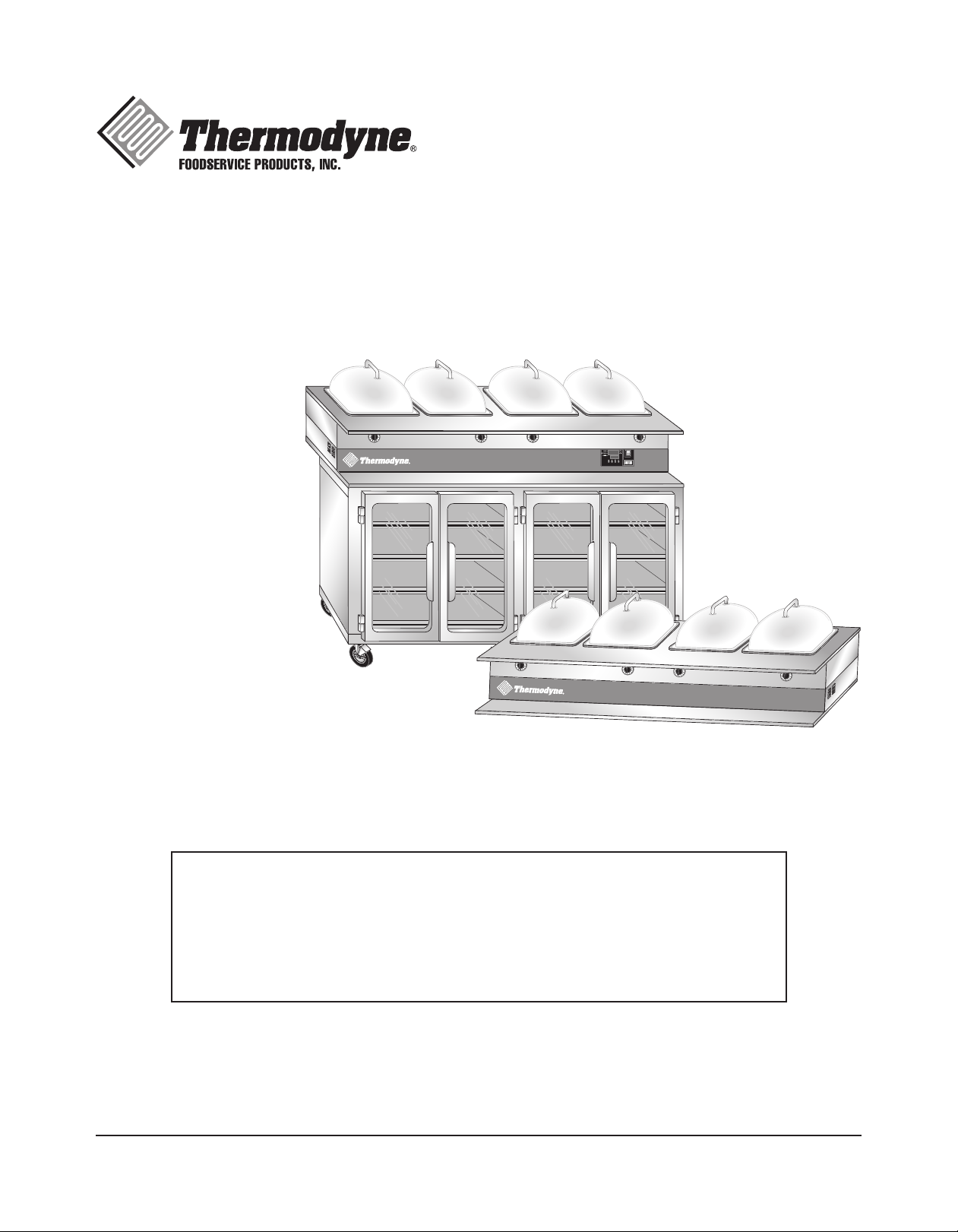
THERMODYNE 742HW-CT User manual
INSTALLATION &
OPERATION MANUAL
(01-20)
DRY WELL MODELS
742HW 742HW-CT (Countertop 6 Inch Deep Wells)
744HW 744HW-CT (Countertop 4 Inch Deep Wells)
744HW-CT (Countertop 6 Inch Deep Wells)
Thermodyne Foodservice Products, Inc.
4418 New Haven Avenue 1-800-526-9182
Fort Wayne, IN 46803 www.tdyne.com
For additional information on Thermodyne Foodservice Products, Inc.,
or to locate an authorized parts and service provider in your area,
visit our website at www.tdyne.com.
Please visit our website to Register your Thermodyne unit. Registration ensures that you
get up-to-date warranty and product information, along with fast and convenient service.
http://www.tdyne.com/register.aspx
— 2 —
IMPORTANT FOR YOUR SAFETY
THIS MANUAL HAS BEEN PREPARED FOR PERSONNEL QUALIFIED TO INSTALL ELECTRICAL
EQUIPMENT, WHO SHOULD PERFORM THE INITIAL FIELD STARTUP AND ADJUSTMENTS OF
THE EQUIPMENT COVERED BY THIS MANUAL.
READ THIS MANUAL THOROUGHLY BEFORE OPERATING, INSTALLING OR PERFORMING
MAINTENANCE ON THE EQUIPMENT.
: Failure to follow all the instructions in this manual can cause property damage,
injury or death.
: Improper installation, adjustment, alteration, service or maintenance can cause
property damage, injury or death.
: Electrical connections should be performed only by a certified professional.
: Electrical and grounding connections must comply with the applicable portions
of the National Electric Code and/or all local electric codes. Failure to comply with this
procedure can cause property damage, injury or death.
: Before connecting the unit to the electrical supply, verify that the electrical and
grounding connections comply with the applicable portions of the National Electric Code and/or
other local electrical codes. Failure to comply with this procedure can cause property damage,
injury or death.
: Before connecting the unit to the electrical supply, verify that the electrical
connection agrees with the specifications on the data plate. Failure to comply with this
procedure can cause property damage, injury or death.
: UL73 grounding instructions:This appliance must be connected to a grounded,
metal, permanent wiring system. Or an equipment-grounding conductor must be run with the
circuit conductors and connected to the equipment-grounding terminal or lead on the appliance.
Failure to comply with this procedure can cause property damage, injury or death.
: Appliances equipped with a flexible electric supply cord, are provided with
a three-prong grounding plug. It is imperative that this plug be connected into a properly
grounded three-prong receptacle. Failure to comply with this procedure can cause property
damage, injury or death.
: If the receptacle is not the proper grounding type, contact an electrician. Do not
remove the grounding prong from the plug. Failure to comply with this procedure can cause
property damage, injury or death.
: Before performing any service that involves electrical connection or
disconnection and/or exposure to electrical components, always perform the Electrical
LOCKOUT/TAGOUT Procedure. Disconnect all circuits. Failure to comply with this procedure
can cause property damage, injury or death.
— 3 —
: Before removing any sheet metal panels or servicing this equipment, always
perform the Electrical LOCKOUT/TAGOUT Procedure. Be sure all circuits are disconnected.
Failure to comply with this procedure can cause property damage, injury or death.
: Do not operate this equipment without properly placing and securing all covers
and access panels. Failure to comply with this procedure can cause property damage, injury or
death.
: Do not use or store gasoline or other flammable vapors or liquids in the vicinity
of this or any other appliance. Failure to comply can cause property damage, injury or death.
: In the event of a power failure, do not attempt to operate this appliance. Failure to
comply can cause property damage, injury or death.
CAUTION: These models have glass doors. Remove carton carefully.
FOR YOUR SAFETY
DO NOT STORE OR USE GASOLINE OR OTHER FLAMMABLE
VAPORS OR LIQUIDS IN THE VICINITY OF THIS OR ANY OTHER
APPLIANCE. FAILURE TO COMPLY CAN CAUSE PROPERTY
DAMAGE, INJURY OR DEATH.

— 4 —
TABLE OF CONTENTS
IMPORTANT FOR YOUR SAFETY................................................................................................... 2
INTRODUCTION .............................................................................................................................. 5
GENERAL .................................................................................................................................. 5
SPECIFICATIONS ...................................................................................................................... 5
UNPACKING............................................................................................................................... 8
Thermodyne Damaged Goods Policy................................................................................... 8
INSTALLATION CODES AND STANDARDS.............................................................................. 8
ELECTRICAL SPECIFICATIONS............................................................................................... 9
INSTALLATION................................................................................................................................. 9
LOCATION.................................................................................................................................. 9
ELECTRICAL CONNECTION .................................................................................................... 9
OPERATION................................................................................................................................... 10
CONTROLS AND INDICATORS............................................................................................... 10
STARTUP ................................................................................................................................. 10
Setting Cabinet Temperature .............................................................................................. 11
Setting Well Temperature.................................................................................................... 11
Preheating .......................................................................................................................... 11
FLUID REPLENISHMENT........................................................................................................ 12
CLEANING AND MAINTENANCE ................................................................................................. 13
ELECTRICAL LOCKOUT/TAGOUT PROCEDURE.................................................................. 13
WHEN TO CLEAN .................................................................................................................... 13
STAINLESS STEEL CARE....................................................................................................... 13
Cleaning.............................................................................................................................. 13
Preserving & Restoring....................................................................................................... 13
Heat Tint ............................................................................................................................. 14
CLEANING HEAT TRANSFER PLATES................................................................................... 14
CLEANING DOOR GASKETS ................................................................................................. 14
CHANGING FLUID................................................................................................................... 14
CLEANING THE DRY WELL .................................................................................................... 15
TROUBLESHOOTING.................................................................................................................... 17
SCHEMATIC WIRING DIAGRAM................................................................................................... 18
WARRANTY ................................................................................................................................... 19
HEAT TRANSFER FLUID MSDS ................................................................................................... 19
— 5 —
SPECIFICATIONS
INTRODUCTION
GENERAL
Thermodyne cabinets are produced with quality
workmanship and materials. Proper installation,
operation and maintenance will result in many
years of satisfactory performance. It is suggested
that you thoroughly read this manual in its entirety
and carefully follow all of the instructions provided.
The cabinets described in this manual are
programmable for the desired holding temperature.
The factory setting is 185° F unless otherwise
specified. Each shelf in the cabinet maintains an
exact temperature, allowing for extended holding
times without sacrificing appearance or taste.
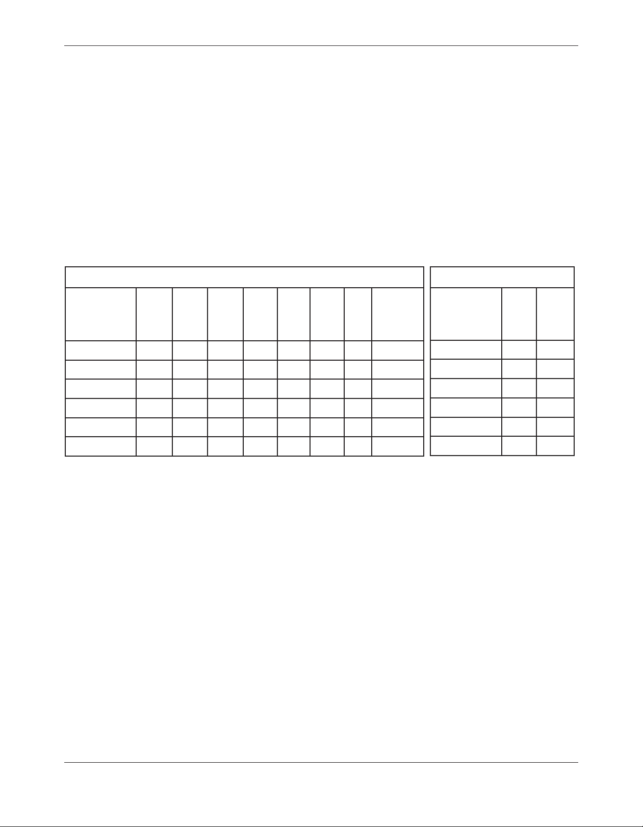
DIMENSIONS AND MAXIMUM TEMPERATURE
Model
Ext.
Width
inches
Ext.
Depth
inches
Ext.
Height
inches
Int.
Width
inches
Int.
Depth
inches
Int.
Height
inches
Max.
Oper.
Temp
°F
Max. Oper.
Temp Dry
Well °F
742HW
31.750 33.625 37.50 26.50 22.50 20.00 230 250
744HW
60.125 33.625 37.50 56.00 22.50 20.00 230 250
742HW-CT
30.50 27.50 13.125 – – – – 250
744HW-CT
60.125 33.00 13.125 – – – – 250
742HW-CT (6in)
30.50 33.00 15.125 – – – – 250
744HW-CT (6in)
60.125 33.00 15.125 – – – – 250
WEIGHT
Model
Net
Weight
lbs
Shipping
Weight
lbs
742HW
265 340
744HW
470 560
742HW-CT
110 200
744HW-CT
215 310
742HW-CT (6in)
145 245
744HW-CT (6in)
205 430

— 6 —
Figure 2: Outline Dimensional Drawing, 742HW-CT Countertop with 6 Inch Deep Wells
Figure 1: Outline Dimensional Drawing, 742HW-CT Countertop
DEEP HOUSING LID SHELF OPTION SHOWN
DEEP BASE SHELF
OPTION SHOWN
33"
13" 8"
Exterior Depth
FRONT VIEW
TOP VIEW
SIDE VIEW
ELECTRICAL
10 3/8"
30 1/2"
Exterior Width
15 1/8"
Exterior
Height
27 1/2"
Exterior Depth
FRONT VIEW
TOP VIEW
SIDE VIEW ELECTRICAL
23 7/8"
30 1/2"
Exterior Width
13 1/8"
Exterior
Height

— 7 —
Figure 4: Outline Dimensional Drawing, 744HW with Casters
Figure 3: Outline Dimensional Drawing, 744HW-CT Countertop
32"
11"
11"
8"
ELECTRICAL
ELECTRICAL
60 1/8"
Ext. Width
56"
Int. Width
FRONT VIEW
SIDE VIEW
TOP VIEW
20"
Int.
Height
37 1/2"
Ext.
Height
1-3/4" WIDE
2" DIA. WHEEL
2 1/2"
SPACING
4" PAN
SPACING
33 5/8"
Ext. Depth
22 1/2"
Int. Depth
OFF
60
100
250
150
200
OFF
60
100
250
150
200
OFF
60
100
250
150
200
OFF
60
100
250
150
200
33"
Exterior Depth
60 1/8"
Exterior Width
13 1/8"
Exterior
Height
FRONT VIEW
TOP VIEW
SIDE VIEW
REAR VIEW
ELECTRICAL
ELECTRICAL
ELECTRICAL
11"
8"
OFF
60
100
250
150
200
OFF
60
100
250
150
200
OFF
60
100
250
150
200
OFF
60
100
250
150
200
11"

— 8 —
UNPACKING
All Thermodyne cabinets are factory tested for
performance and certified free from defects.
Thermodyne Damaged Goods Policy
There are two types of damaged merchandise:
A. Visible Damage and B. Concealed Damage.
A. Visible Damage: The product being received
is visibly damaged.
1. The receiver should refuse the damaged
merchandise.
2. Receiver should sign the bill of lading
indicating which merchandise is being
refused due to damage.
3. Contact Thermodyne Customer Service
Representatives immediately.
B. Concealed Damage:Damaged merchandise
cannot be externally detected.
Your receiving operation should inspect for this
type of damage. Please inspect your delivery
carefully.
If the product is damaged:
1. Save all packing material.
2. Contact Thermodyne Customer Service
Representatives immediately.
3. Receiver must call the carrier to schedule
an inspection of the damaged merchandise
within 5 business days.
INSTALLATION CODES
AND STANDARDS
These installation instructions are for the use of
qualified installation and service personnel
only.
1. Installation or service by other than qualified
personnel may result in damage to the
Thermodynecabinet and/orinjuryto theoperator.
2. National Electrical Code (ANSI/NFPA No. 70,
latest edition) available from the National Fire
Protection Association, Batterymarch Park,
Quincy, MA 02269.
In Canada, the cabinet must be installed in
accordance with:
1. Local codes.
2. Canadian Electrical Code (CSA C22.2 No.
3, latest edition) available from the Canadian
Standards Association, 5060 Spectrum Way,
Mississauga, Ontario, Canada L4W 5N6.
Figure 5: Outline Dimensional Drawing, 744HW-CT Countertop with 6 Inch Deep Wells
OFF
60
100
250
150
200
OFF
60
100
250
150
200
OFF
60
100
250
150
200
OFF
60
100
250
150
200
DEEP HOUSING LID SHELF OPTION SHOWN
DEEP BASE SHELF
OPTION SHOWN
WELLS FOR 6" PANS
33"
Exterior Depth
60 1/8"
Exterior Width
15 1/8"
Exterior
Height
FRONT VIEW
TOP VIEW
SIDE VIEW
REAR VIEW
ELECTRICAL
ELECTRICAL
ELECTRICAL
13"
8"
10 3/8"
— 9 —
Before installing, verify the required electrical
supply agrees with the specifications on the data
plate located on the back or side of the unit. If
the supply and equipment requirements do not
agree, do not proceed with installation. Contact
your dealer orThermodyne Foodservice Products,
Inc. immediately.
CAUTION: These models have glass doors.
Remove carton carefully.
1. Allow ample overhead clearance for removal
of carton.
2. Cut banding (2 pieces) and remove nails (not
for all units).
3. To remove cabinet from carton, slide carton
up and off the cabinet.
4. Check packing list against items received:
A. Thermodyne Heat Transfer Fluid
B. Installation & Operation Manual
5. Use proper lifting equipment to raise the
cabinet.
6. Remove the plastic covering from glass door
frames and hinges.
7. Mount doors on cabinet, and then check doors
for alignment.
8. Set cabinet on a level surface.
LOCATION
Allow adequate space for electrical connections.
The electrical cord and plug are located at the right
rear of the unit.The minimum clearance for proper
air circulation on back should be 4”, and 2” on at
least one side. Allow adequate access space for
operating and servicing the unit.
NOTICE: Louvers on the sides of the oven
are used to circulate cool air throughout the
electrical components. The unit must not be
placed where extensive airborne grease is
present, such as near deep fryers or griddles.
ELECTRICAL CONNECTION
: Electrical and grounding
connections must comply with applicable
portions of the National Electrical Code and/
or other local electrical codes.
: Disconnect the electrical
power to the Thermodyne unit and follow
LOCKOUT/TAGOUT procedures.
Refer to the wiring diagrams in this manual for
wiring information.
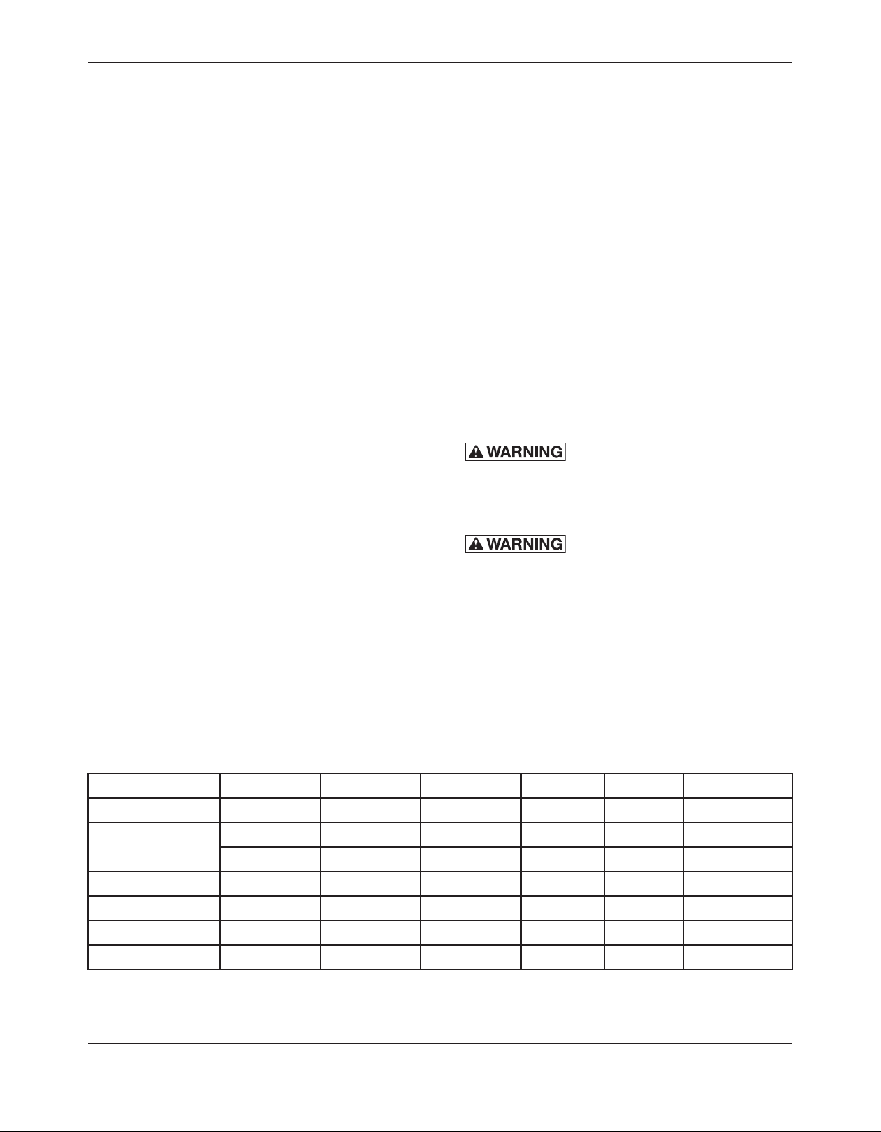
MODEL VOLTS AMPS WATTS HERTZ PHASE PLUG
742HW 208/240 22/23 4730/5500 60 1 NEMA 14-30
744HW* 208/240 25/27 5250/7000 60 1 NEMA 14-30
208/240 15/17 3440/4000 60 1 NEMA 6-30
742HW-CT 208/240 8/9 1770/2000 60 1 NEMA 6-30
744HW-CT 208/240 15/17 3440/4000 60 1 NEMA 6-30
742HW-CT (6in) 208/240 8/9 1540/2040 60 1 NEMA 6-15
744HW-CT (6in) 208/240 15/17 3120/4080 60 1 NEMA 6-30
* Two (2) plugs required for this unit.
ELECTRICAL SPECIFICATIONS
INSTALLATION
— 10 —
OPERATION
STARTUP
: The oven cabinet and hot
wells are hot. Use care when operating,
cleaning or servicing this equipment.
Once the cabinet is installed and electrical
connections have been made, thoroughly test the
Thermodyne cabinet before operation.
1. Check that all packing materials and other
items have been removed from the cabinet.
2. Press the Power ON/OFF Switches to the ON
position. The operating temperature will be
reached in approximately 30 minutes.
3. Check ADD FLUID Light.
• OVENCONTROL:Ifthelightremainson
or flickers continuously, it indicates that
some fluid was lost during shipment. Add
fluid as described in the section FLUID
REPLENISHMENT.
• HOT WELL CONTROL: Adjust knob to
desired temperature for each well. The
light remains illuminated until desired
temperature is reached. Knobs are labeled
1-10, with 10 being the hottest.
NOTE: The controller has an HEATER
INDICATOR (red lamp).This light blinks
as the controller maintains the desired
temperature.
Size, weight, pan loading, and product quality will
affect cooking times and should be adjusted to fit
the requirements of your operation.
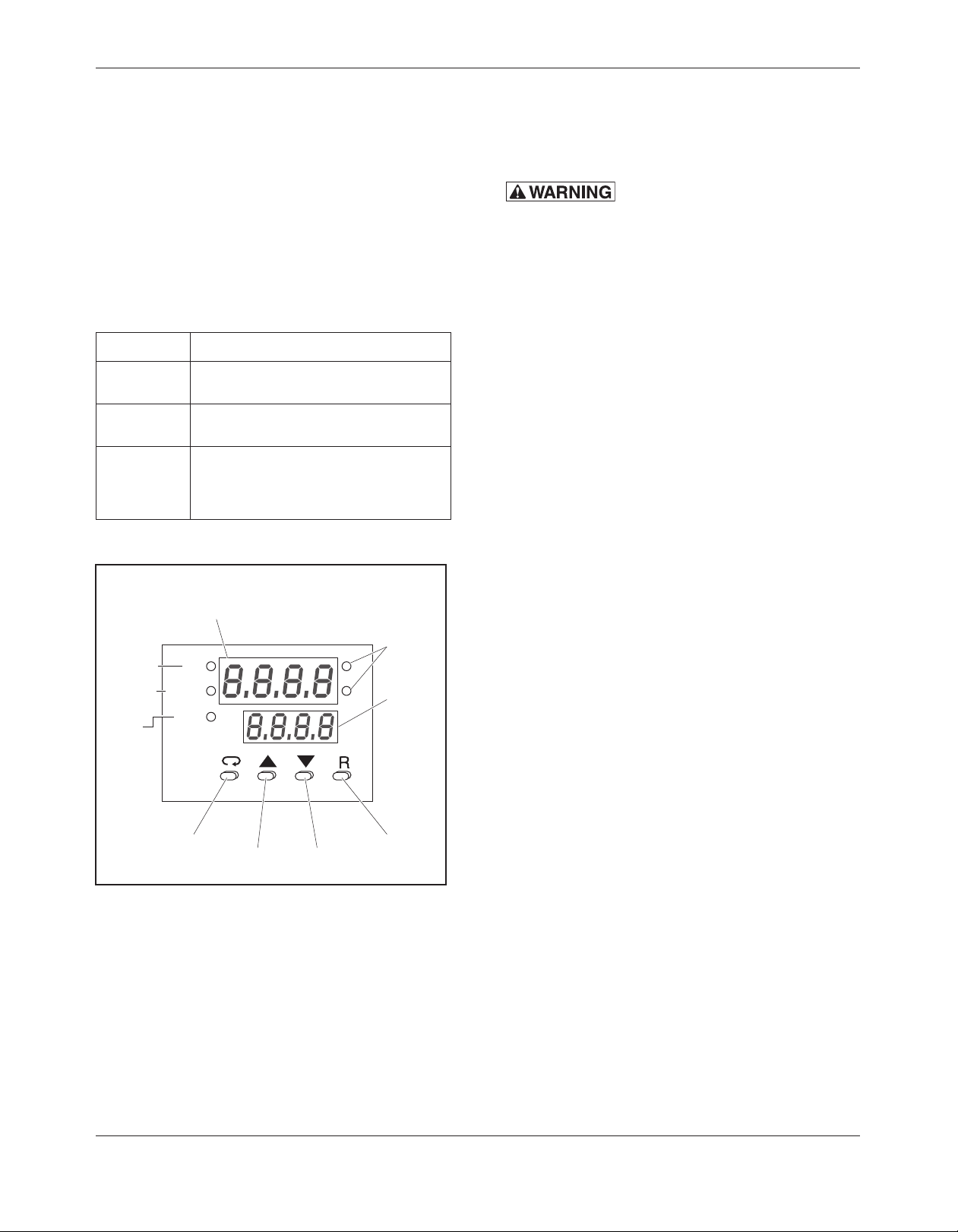
CONTROLS AND INDICATORS
All controls are located at the top right front of the
Thermodyne cabinet:
• Thedigitalcontrolnearthecabinet’sright
side controls the oven.
• Controlknobsareusedtoadjust
temperatures for each well opening.
ITEM FUNCTION
ON/OFF
Switch
When lit, it indicates the unit is turned on.
ADD FLUID
Light (Red)
When lit, it indicates additional fluid is
required.
Cabinet
Controller
Provides readout of actual temperature
and desired temperature. It has increase
and decrease buttons for setting the
desired temperature.
Heater
Indicator
Process
Unit
Indicator
(Contop,
Fonbottom)
Lower
Display
To display
set point
value,
parameter
value,
control
output
value, etc.
Upper Display
To display process value,
menu symbol, error code, etc.
Scroll
Key
Output 2
Indicator
Alarm
Indicator
Up
Key
Down
Key
Return/Reset
Key
HEAT
OUTPUT 2
ALARM
°C
°F
Figure 6: Control Panel
— 11 —
Setting Cabinet Temperature
1. To set temperature:
KEY FUNCTION
Up Press and release quickly to
Key increase the value of the
displayed parameter.
Press and hold to accelerate
increment speed.
Down Press and release quickly to
Key decrease the value of the
displayed parameter.
Press and hold to accelerate
decrement speed.
2. Heater Indicator light will illuminate while the
cabinet is warming up.
3. When the Heater Indicator light is blinking,
the cabinet has reached the desired/set
point temperature.
NOTE: The controller is not an indicator of fluid
level in the heater or reservoir tank.
Heater
Indicator
Process
Unit
Indicator
(Contop,
Fonbottom)
Lower
Display
To display
set point
value,
parameter
value,
control
output
value, etc.
Upper Display
To display process value,
menu symbol, error code, etc.
Scroll
Key
Output 2
Indicator
Alarm
Indicator
Up
Key
Down
Key
Return/Reset
Key
HEAT
OUTPUT 2
ALARM
°C
°F
Figure 7: Control Panel Functions
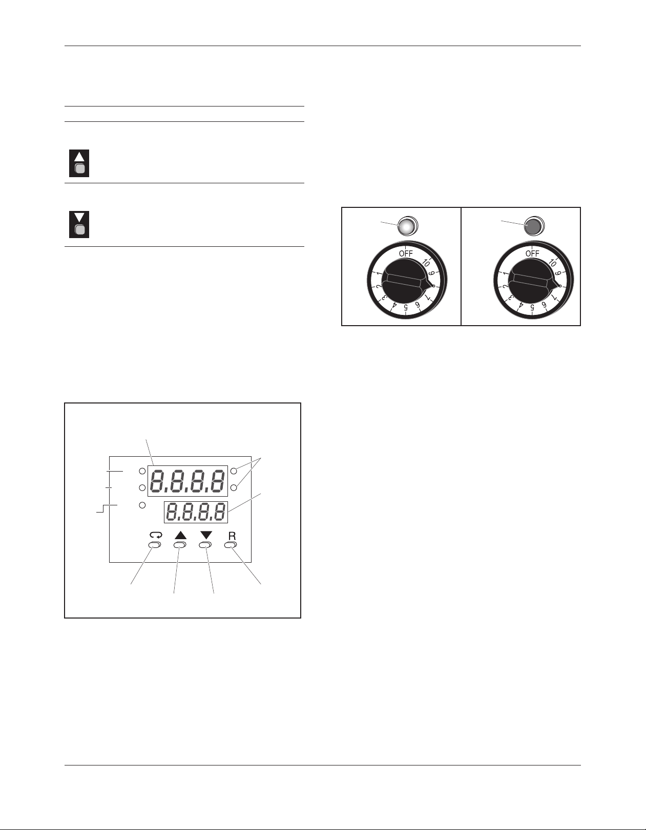
Setting Well Temperature
Each well can be set to its own temperature on a
1-10 scale, with 10 being the hottest setting. The
light is illuminated while the well is heating, however
it will turn off once set temperature is reached.
NOTE: The wells in this unit are dry wells and
water should not be added for heating.
Well is
heating
Set
temperature
is reached
Figure 8: Well Temperature Light
Preheating
Preheat the Thermodyne cabinet when first used
for the day or whenever the unit is cold.Preheating
takes approximately 30 minutes at which time the
temperature set point and the actual temperature
will display the same temperature. If the cabinet
has door(s), keep the doors closed during the
preheat cycle.

— 12 —
FLUID REPLENISHMENT
CAUTION: Use only supplied Thermodyne
Heat Transfer Fluid.
: Disconnect the electrical
power to the hot well and perform
LOCKOUT/TAGOUT procedure.
CAUTION: The cabinet and the hot well may
be hot, allow them to cool before beginning
this procedure.
1. Move the Hot Well power ON/OFF switch to
its OFF position. DO NOT turn the oven off.
2. Using the handle, raise the hot well to gain
access to the power head.
3. Place the safety catch in its holder.
Safety
Catch
Figure 9: Hot Well in Raised Position
4. Remove the reservoir tank cap.
Reservoir
Tank
Observe ADD FLUID light.
Reservoir
Tank Cap
Figure 10: Reservoir Tank Replenishment
5. Fill reservoir tank until oven controller ADD
FLUID light turns off.
6. Re-install the reservoir tank cap and fill cap
cover.
NOTE: If the ADD FLUID Light remains on after
theThermodyne unit has been filled, refer
to TROUBLESHOOTING.

— 13 —
CLEANING AND MAINTENANCE
ELECTRICAL LOCKOUT/TAGOUT
PROCEDURE
: Before performing any
cleaning or maintenance that involves
electrical connection or disconnection
and/or exposure to electrical components,
always follow the Electrical LOCKOUT/
TAGOUT Procedure. Disconnect all circuits.
Failure to comply can cause property
damage, injury or death.
The Electrical LOCKOUT/TAGOUT Procedure is
used to protect personnel working on an electrical
appliance. Before performing any maintenance
or service that requires exposure to electrical
components, follow these steps:
1. In electrical box, place appliance circuit breaker
into OFF position.
2. Place a lock or other device on electrical box
cover to prevent someone from placing circuit
breaker ON.
3. Place a tag on electrical box cover to indicate
that appliance has been disconnected for
service and power should not be restored until
tag is removed by maintenance personnel.
4. Disconnect appliance power cord from
electrical outlet.
5. Place a tag on the cord to indicate that unit
has been disconnected for service and power
should not be restored until tag is removed by
maintenance personnel.
WHEN TO CLEAN
It is recommended that all stainless steel
equipment be cleaned on a regular basis. Any
piece of stainless steel equipment that is soiled
should be cleaned daily to ensure the long life of
the equipment. Routine cleaning will also lessen
stainless steel abrasion.
STAINLESS STEEL CARE
Cleaning
Stainless steel contains 70-80% iron, which will
rust if not properly maintained. It also contains 12-
30% chromium, which forms an invisible passive,
protective film that shields against corrosion.If the
film remains intact, the stainless steel will remain
intact.However, if the film is damaged, the stainless
steel can break down and rust.To prevent stainless
steel breakdown, follow these steps:
CAUTION: Never use any metal tools.
Scrapers, files, wire brushes or scouring
pads (except for stainless steel scouring
pads) will mar the surface.
CAUTION: Never use steel wool, which will
leave behind particles that rust.
CAUTION: Never use acid-based or chloride-
containing cleaning solutions, which will
break down the protective film.
CAUTION: Never rub in a circular motion.
CAUTION: Never leave any food products or
salt on the surface. Many foods are acidic.
Salt contains chloride.
For routine cleaning, use warm water, mild soap
or detergent and a sponge or soft cloth.
For heavy-duty cleaning, use warm water, a
degreaser and a plastic, stainless steel or Scotch-
Brite pad.
Always rinse thoroughly. Always rub gently in the
direction of the steel grain.
NOTE: Thermodyne recommends covering the
plates in the hot well area with tin foil to
help minimize cleaning. (Hot well area
only, not the interior shelves.)
Preserving & Restoring
Special stainless steel polishing cleaners can
preserve and restore the protective film.
Preserve the life of stainless steel with a regular
application of a high quality stainless steel polishing
cleaner as a final step to daily cleaning.

— 14 —
If signs of breakdown appear, restore the stainless
steel surface. First, thoroughly clean, rinse and
dry the surface. Then, on a daily basis, apply a
high-quality stainless steel polish according to
manufacturer’sinstructions.
Heat Tint
Darkened areas, called heat tint, may appear on
stainless steel exposed to excessive heat, which
causes the protective film to thicken. It is unsightly
but is not a sign of permanent damage.
To remove heat tint, follow the routine cleaning
procedure. Stubborn heat tint will require heavy-
duty cleaning.
To reduce heat tint, limit the exposure of equipment
to excessive heat.
CLEANING HEAT TRANSFER PLATES
The Thermodyne unit operates on the principle
of conduction, rather than convection. Therefore,
it is very important to keep the heat transfer
shelves clean, so heat transfer may take place with
maximum efficiency. It is also very important to
keep the bottom contact surfaces of pots and pans
as clean as possible to ensure even and complete
heat transfer. The surface and flat coating of the
thermal heat transfer shelf is extremely hard, but
will react with strong caustic cleaning solutions
and deteriorate.
CAUTION: Most concentrated soaps and
ammonia cleaners are too caustic to be
used on the Thermodyne unit.
If the coating is destroyed, the heat transfer shelves
will lose their non-stick properties and their surface
hardness.
The cleaners should always be used at the
recommended concentrations. In the case of dry
powders, the powders must not be placed directly
on the surface of the heat transfer plate. Care
must be taken not to scratch the shelf surfaces
when using brushes or pads. If harsh scouring is
needed, use a nylon type scouring pad. NEVER
use steel wool.
It is recommended that a weekly cleaning schedule
be followed to avoid the buildup of heavy food
product deposits. In the event heavy deposits
occur that are difficult to remove with ordinary
cleaning procedures, stronger chemical cleaning
agents may be applied if the products are intended
for food service use and are also compatible with
hard coat anodized aluminum surfaces. When
using these stronger solvents, it is very important
that heat transfer shelves are rinsed thoroughly
with clean potable water after cleaning. Be sure to
remove all traces of the cleaning agent. Between
the regular scheduled cleaning, wipe off the
anodized aluminum surfaces periodically with a
clean damp cloth.
CLEANING DOOR GASKETS
Cleanthe gasket-sealing surfaceof theThermodyne
doors to remove food product acids for maximum
gasket life. Do not use any solvents or sharp
instruments as these will damage the gasket.
Wash with a cloth moistened in a solution of mild
detergent and warm water. Rinse with a fresh cloth
moistened with warm water to remove all traces of
detergent.Wipe dry with a clean cloth. Never apply
food product oils or petroleum lubricants directly
to the door gasket as these will reduce gasket life.
CHANGING FLUID
NOTICE:TheThermodyne HeatTransfer Fluid has
lubricating additives, anticorrosion additives, and
heat transfer properties that may decrease with
the passing of time. Thermodyne Heat Transfer
Fluid will protect the unit indefinitely if the fluid is
changed on an annual basis.
CAUTION:The following procedure is to be
performed by a qualified service technician only.
: Before removing any sheet
metal panels or servicing this equipment,
always perform the Electrical LOCKOUT/
TAGOUT Procedure. Be sure all circuits are
disconnected. Failure to comply with this
procedure can cause property damage,
injury or death.
1. Move Power ON/OFF switches to the OFF
position and perform LOCKOUT/TAGOUT
procedures.

— 15 —
2. Allow the unit to cool completely.
3. Using the overhang of the well section, raise
the hot well unit to its up position.
4. Place the safety catch in its holder.
Safety
Catch
Figure 11: Hot Well in Raised Position
5. Locate heater tank and remove cap.
Heater
Tank
Heater
Tank Cap
Figure 12: Heater Tank and Cap
6. Remove left side panel to gain access to drain
valve.
7. Place a pan or bucket beside drain plug in
order to catch drained fluid.
Return
Manifold
Drain
Hose
Drain
Valve
Figure 13: Drain Hose
8. Place drain hose into pan or bucket and turn
valve to open position.
9. Once unit has drained completely turn valve
to off position and tuck drain hose back into
cabinet.
10. Reattach the left side panel.
11. Refill the unit with Thermodyne Heat Transfer
Fluid only.Never substitute with water or other
liquids.
12. Reattach the heater tank cap.
13. Restore power to the unit and place the Power
ON/OFF switch in its ON position.
NOTE: Unit may run briefly and shut off due to
low fluid level.
14. Remove reservoir cap and heater tank cap
and fill heater tank.
Heater
Tank
Heater
Tank Cap
Figure 14: Heater Tank Cap & Reservoir Cap
— 16 —
15. Repeat steps 12-14 until unit is completely full
of fluid.
16. Once unit is completely filled, reattach the
heater tank cap and the powerhead lid.
NOTE: If ADD FLUID light is on, add fluid to
reservoir tank until light goes out.
17. Allow the unit to heat until set temperature is
reached.
18. Once set temperature is reached, place the
power switch in the OFF position and let the
unit cool down to at least 100°F.
19. Turn unit back on, and if ADD FLUID light is
on again, add fluid to reservoir tank until light
goes out.
NOTE: Steps 17-19 are very critical in order to
purge any trapped air from the unit.
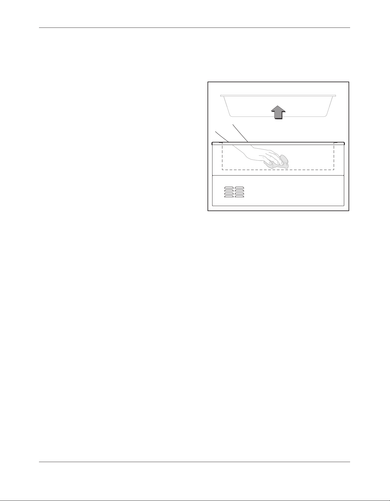
CLEANING THE DRY WELL
With the wells empty, wipe any debris or loose
food from dry well section with rag. (Be Careful,
well section can still be hot).
Holding Pan
Figure 15: Cleaning the Dry Well

— 17 —
TROUBLESHOOTING
Most problems associated with the holding cabinet are due to low fluid level.
Always check fluid level first.
PROBLEM POSSIBLE CAUSE SOLUTION
No Power
1.Main power switch off.
2.Not plugged in.
3.Breaker off or tripped.
4.Bad contactor.
1.Turn switch on.
2.Check plug.
3.Check breaker.
4.Replace contactor.
LOW FLUID light is on –
Oven heating properly
1.Oven is low on fluid. 1.Add Thermodyne Heat Transfer Fluid
per instructions.
LOW FLUID light is on –
Oven not heating properly
1.Oven disabled due to low fluid
level cut out.
2.Fluid level probe defective.
3.System leak.
1.Main heater tanks low on fluid. Add
Thermodyne Heat Transfer Fluid and
determine cause of fluid loss.
2.Repair or replace.*
3.Repair leak.*
Heater(s) not working
1.Unit not properly wired.
2.Bad heater(s).
3.Contactor or solid state relays
not working.
4.Off due to low fluid cut out.
5.Failed temperature controller.
6.High limit snap disc tripped.
1.Check wiring.*
2.Replace heater(s).*
3.Repair or replace.*
4.Add Thermodyne Heat Transfer Fluid
per instructions.
5.Replace temperature controller.*
6.Reset snap disc and check for cause.*
Shelves hotter than
set point
1.Temperature controller out of
calibration.
2.Thermocouple defective.
3.Solid state relay(s) stuck on.
4.Failed temperature controller.
1.Recalibrate temperature controller.*
2.Replace thermocouple.*
3.Replace solid state relay(s).*
4.Replace temperature controller.*
Shelves colder than
set point
1.Low fluid in tank. (LOW FLUID
light should be lit)
2.Failed temperature controller.
3.Heater(s) not working.
4.Pump failure.
5.Thermocouple failure.
1.Add Thermodyne Heat Transfer Fluid
per instructions.
2.Replace temperature controller.*
3.See “Heater(s) not working”.
4.Repair or replace pump.
5.Replace thermocouple.
Oven heats up too slow 1.Heater(s) not working. 1.See “Heater(s) not working”.
*Recommended service to be done by a qualified service agency.
NOTE: Most problems associated with the Thermodyne cabinet are due to failure to add Thermodyne
Heat Transfer Fluid. Check fluid level first. In the event service is required on your Thermodyne
cabinet, please call: (800) 526-9182.

— 18 —
SCHEMATIC WIRING DIAGRAM

— 19 —
WARRANTY
Thermodyne Foodservice Products, Inc.
warrants to the original purchaser for use of
each new Thermodyne Conductive Cooking/
Holding Oven the following: Any part which
proves to be defective in materials or
workmanship within the warranty period
will, subject to the terms of this warranty,
be repaired or replaced at Thermodyne
Foodservice,Inc.’soption.Claimsunderthis
warranty must be presented to Thermodyne
Foodservice Products, Inc. in writing, promptly.
Thermodyne stainless steel cabinets are
warranted for 5 years and all other original
equipment parts such as heat transfer plates,
doors, casters, fluid system components and
electrical components are warranted against
defect for 2 years from the date of purchase.
This warranty applies only to Thermodyne
Conductive Cooking/Holding Ovens in the
Continental United States. This warranty shall
not apply if the oven or any part is subjected to
accident, casualty, alteration, misuse, abuse,
neglect, faulty installation, or if the date of
manufacture is altered or removed.
The obligation of Thermodyne Foodservice
Products, Inc. is limited specifically to the
aforementioned. No additional guarantees
or warranty, expressed or implied, to include
without limitation warranties of Fitness or
Merchantability with respect to Thermodyne
Conduction Ovens and Thermodyne
Foodservice Products, Inc. regarding other
liability with respect thereto including, without
limitation, liability for incidental, special, or
consequential damages.
RESPONSIBILITIES OF PURCHASER
It is the responsibility of the purchaser to:
1. Arrange on site electrical services
in accordance with Thermodyne
specifications.
2. Receive shipment of Thermodyne
conduction oven to include unloading,
uncrating, inspecting for damage in
shipment, and installation of the oven in
its proper location; in accordance with
installation instructions.
3. Arrange that the electric services are
connected properly by a qualified
technician. All such connections must
be in accordance with applicable code
requirements and Thermodyne installation
procedures.
Please note the specific details on the Warranty
and make certain that service connections
are made to the proper utility services. This
warranty and purchasers responsibility
information should be retained for future
reference.
For assistance please call:
Toll Free: (800) 526-9182
Local: (260) 428-2535
HEAT TRANSFER FLUID MSDS
Dow Chemical U.S.A.
Midland, MI 48674
Emergency Phone: 517-636-4400
Product Code: 23545
Product Name: PROPYLENE GLYCOL
HEAT TRANSFER FLUID
Effective Date: 03-02-88
Date Printed: 06/02/88
MSDS: 000130
1. INGREDIENTS:
Propylene glycol CAS# 000057-55-6
95%
Dipotassium phosphate CAS# 007758-
11-4 <5%
Deionized water CAS# 007732-18-5 <5%
This documentis prepared pursuant tothe
OSHA Hazard Communication Standard
(29CFR 1910.1200). In addition, other
substances not ‘Hazardous’ per this
OSHA Standard may be listed. Where
proprietary ingredient shows, the identity
may be made available as provided in
this standard.
2. PHYSICAL DATA:
BOILING POINT: 370F, 188C
VAP. PRESS: 0.22 mmHg @ 20C, 68F
VAP. DENSITY: 2.62
SOL. IN WATER; Complete
SP. Gravity: 1,050 @ 60/60F, 16C
APPEARANCE: Colorless.
ODOR: Odorless liquid.
3. FIRE AND EXPLOSION HAZARD DATA:
FLASH POINT: 215F, 102C
METHOD USED: COC
FLAMMABLE LIMITS
LFL: 2.6% @ 100C
UFL: 12.5% @ 130C
EXTINGUISHING MEDIA: Water fog,
alcohol foam, dry chemical
FIRE AND EXPLOSION HAZARDS:
None.
FIRE-FIGHTING EQUIPMENT: None.
4. REACTIVITY DATA:
STABILITY: (CONDITIONS TO AVOID)
Stable over normal
Operating temperature range of –30F
to 250F.
INCOMPATIBILITY: (SPECIFIC
MATERIALS TO AVOID)
Oxidizing material.
HAZARDOUS DECOMPOSITION
PRODUCTS: None
HAZARDOUS POLYMERIZATION: Will
not occur,
5. ENVIROMENTAL AND DISPOSAL
INFORMATION:
ACTIONTOTAKE FOR SPILLS/LEAKS:
Cover with absorbent material, soak up
and sweep into bag.
6. HEALTH HAZARD DATA:
EYE: May cause slight transient eye
irritation. Corneal injury is unlikely.
SKIN CONTACT:Essentially nonirritating
to skin on prolonged contact.
SKIN ABSORPTION:A single prolonged
skin exposure is not likely to result in
absorption of harmful amounts. The
LD50 for skin absorption in rabbits is
>10,000 mg/kg.
Repeated exposures may cause slight
flaking, tenderness and softening of skin.
INGESTION: Single does oral toxicity is
low. The LD50 for female rats is about
20.3 g/kg
INHALATION:A single prolonged (hours)
inhalation exposure is not likely to cause
adverse side effects. Mists are not to be
hazardous.
SYSTEMIC & OTHER EFFECTS:
Repeated excessive ingestion may
cause central nervous system effects.
No carcinogenic effects have been
seen in long-term animal studies. Birth
defects are unlikely. Exposures having
no adverse effects on the mother
should have no effect on the fetus. In
animal studies, has been shown not to
interfere with reproduction. Results of
mutagenicity tests in vitro (test tube) and
in animals have been negative.
7. FIRST AID
EYES: Irrigate immediately with water
for at least 5 minutes.
SKIN:wash off in flowing water or shower
INGESTION: Induce vomiting if large
amounts are ingested, consult medical
INHALATION: Remove to fresh air if
effects occur. Consult medical.
NOTE TO PHYSICIAN: No specific
antidote. Supportive care. Treatment
based on judgment of the physician in
response to reactions of the patient.
8. HANDLING PRECAUTIONS:
EXPOSURE GUIDELINE (S): Dow IHG
is 10mg/m3 for propylene glycol mist.
Dow IHG 440 ppm for propylene glycol
vapors.
VENTILATION;Good general ventilation
sufficient.
RESPIRATORY PROTECTION: No
respiratory protection should be needed.
SKIN PROTECTION: No precautions
other than clean body covering should
be needed.
EYE PROTECTION:Use safety glasses.
9. ADDITIONAL INFORMATION:
REGULATORY REQUIREMENTS:
SARA HAZARD CATEGORY: This
product has been reviewed according
to the EPA ‘Hazard Categories’
promulgated under Section 311 and
312 of the Superfund Amendment and
Reauthorization Act of 1986 (SARA
Title III) and is considered, under
applicable definitions, to meet the
following categories:A delayed hazard.
SPECIALPRECAUTIONSTOBETAKEN
IN HANDLING AND STORAGE:Exercise
reasonable care and caution.
MSDS STATUS: Revised Section 9

— 20 —
This manual suits for next models
3
Table of contents
Other THERMODYNE Oven manuals


