THERMODYNE 744HW-CT User manual

INSTALLATION &
OPERATION MANUAL
(10-17)
MODELS
742-HW-CT
744-HW-CT
Thermodyne Foodservice Products, Inc.
4418 New Haven Avenue 1-800-526-9182
Fort Wayne, IN 46803 www.tdyne.com
For additional information on Thermodyne Foodservice Products, Inc.,
or to locate an authorized parts and service provider in your area,
visit our website at www.tdyne.com.
Please visit our website to Register your Thermodyne unit. Registration ensures that you
get up-to-date warranty and product information, along with fast and convenient service.
http://www.tdyne.com/register.aspx

— 2 —
IMPORTANT FOR YOUR SAFETY
THIS MANUAL HAS BEEN PREPARED FOR PERSONNEL QUALIFIED TO INSTALL ELECTRICAL
EQUIPMENT, WHO SHOULD PERFORM THE INITIAL FIELD STARTUP AND ADJUSTMENTS OF
THE EQUIPMENT COVERED BY THIS MANUAL.
READ THIS MANUAL THOROUGHLY BEFORE OPERATING, INSTALLING OR PERFORMING
MAINTENANCE ON THE EQUIPMENT.
: Failure to follow all the instructions in this manual can cause property damage,
injury or death.
: Improper installation, adjustment, alteration, service or maintenance can cause
property damage, injury or death.
: Electrical connections should be performed only by a certified professional.
: Electrical and grounding connections must comply with the applicable portions
of the National Electric Code and/or all local electric codes. Failure to comply with this
procedure can cause property damage, injury or death.
: Before connecting the unit to the electrical supply, verify that the electrical and
grounding connections comply with the applicable portions of the National Electric Code and/or
other local electrical codes. Failure to comply with this procedure can cause property damage,
injury or death.
: Before connecting the unit to the electrical supply, verify that the electrical
connection agrees with the specifications on the data plate. Failure to comply with this
procedure can cause property damage, injury or death.
: UL73 grounding instructions:This appliance must be connected to a grounded,
metal, permanent wiring system. Or an equipment-grounding conductor must be run with the
circuit conductors and connected to the equipment-grounding terminal or lead on the appliance.
Failure to comply with this procedure can cause property damage, injury or death.
: Appliances equipped with a flexible electric supply cord, are provided with
a three-prong grounding plug. It is imperative that this plug be connected into a properly
grounded three-prong receptacle. Failure to comply with this procedure can cause property
damage, injury or death.
: If the receptacle is not the proper grounding type, contact an electrician. Do not
remove the grounding prong from the plug. Failure to comply with this procedure can cause
property damage, injury or death.
: Before performing any service that involves electrical connection or
disconnection and/or exposure to electrical components, always perform the Electrical
LOCKOUT/TAGOUT Procedure. Disconnect all circuits. Failure to comply with this procedure
can cause property damage, injury or death.

— 3 —
: Before removing any sheet metal panels or servicing this equipment, always
perform the Electrical LOCKOUT/TAGOUT Procedure. Be sure all circuits are disconnected.
Failure to comply with this procedure can cause property damage, injury or death.
: Do not operate this equipment without properly placing and securing all covers
and access panels. Failure to comply with this procedure can cause property damage, injury or
death.
: Do not use or store gasoline or other flammable vapors or liquids in the vicinity
of this or any other appliance. Failure to comply can cause property damage, injury or death.
: In the event of a power failure, do not attempt to operate this appliance. Failure to
comply can cause property damage, injury or death.
CAUTION: These models have glass doors. Remove carton carefully.
FOR YOUR SAFETY
DO NOT STORE OR USE GASOLINE OR OTHER FLAMMABLE
VAPORS OR LIQUIDS IN THE VICINITY OF THIS OR ANY OTHER
APPLIANCE. FAILURE TO COMPLY CAN CAUSE PROPERTY
DAMAGE, INJURY OR DEATH.

— 4 —
TABLE OF CONTENTS
INTRODUCTION .............................................................................................................................. 5
GENERAL .................................................................................................................................. 5
SPECIFICATIONS ...................................................................................................................... 5
UNPACKING............................................................................................................................... 6
Thermodyne Damaged Goods Policy................................................................................... 6
INSTALLATION CODES AND STANDARDS.............................................................................. 6
INSTALLATION ................................................................................................................................ 7
LOCATION.................................................................................................................................. 7
ELECTRICAL CONNECTION .................................................................................................... 7
ELECTRICAL SPECIFICATIONS ............................................................................................... 7
OPERATION..................................................................................................................................... 8
STARTUP .................................................................................................................................. 8
Temperature Controller Set Up Procedures.......................................................................... 8
Keypad Operation ................................................................................................................. 8
Set-Up................................................................................................................................... 9
To Toggle Between °F and °C Readout:................................................................................ 9
Preheating ............................................................................................................................ 9
CLEANING AND MAINTENANCE ................................................................................................. 10
ELECTRICAL LOCKOUT/TAGOUT PROCEDURE.................................................................. 10
WHEN TO CLEAN .................................................................................................................... 10
STAINLESS STEEL CARE ....................................................................................................... 10
Cleaning.............................................................................................................................. 10
Preserving & Restoring....................................................................................................... 10
Heat Tint ............................................................................................................................. 11
DRAINING WATER FROM HOT WELLS.................................................................................. 11
TROUBLESHOOTING.................................................................................................................... 12
SCHEMATIC WIRING DIAGRAM................................................................................................... 13
WARRANTY ................................................................................................................................... 14

— 5 —
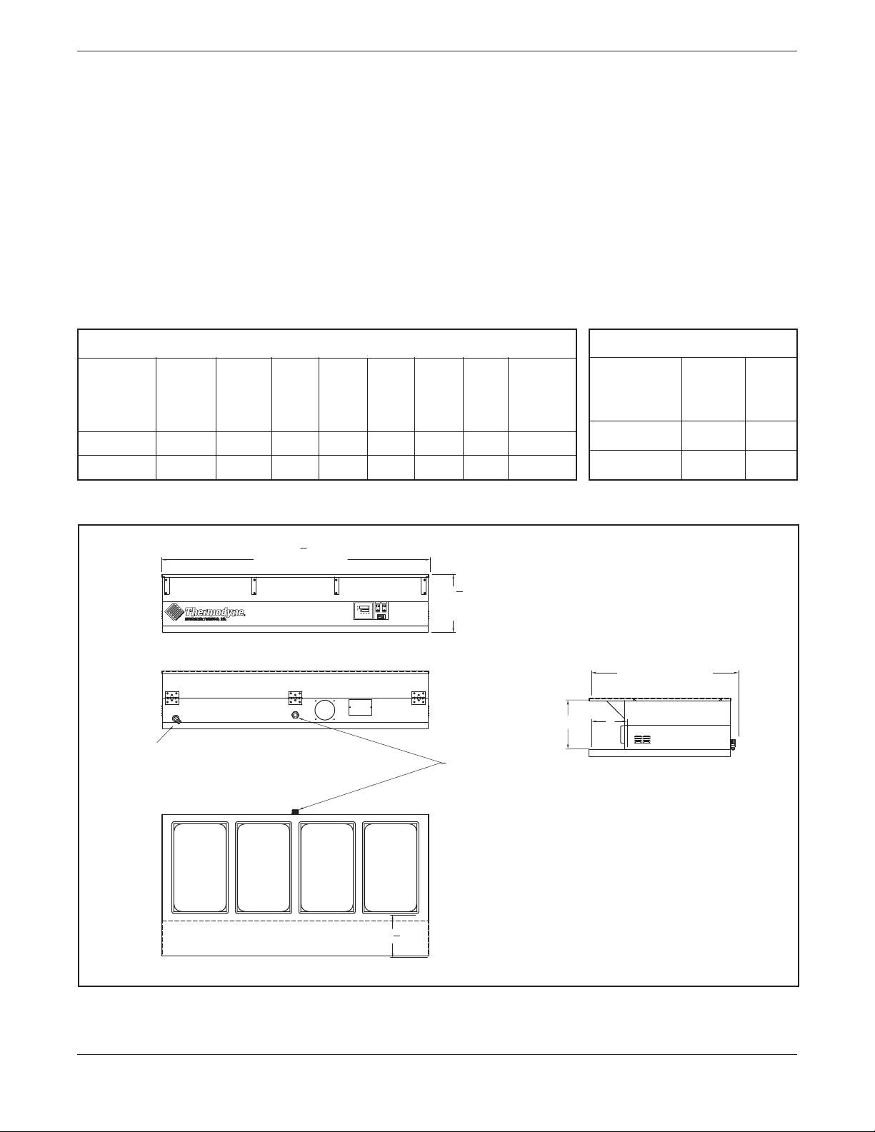
DIMENSIONS AND MAXIMUM TEMPERATURE
Ext. Ext. Ext. Int. Int. Int. Max. Max.
Width Depth Height Width Depth Height Oper. Oper. Temp
inches inches inches inches inches inches Temp Dry Well
°
F
°
F
742 HW-CT
31.750 33.00 13.125 – – – – 211
744 HW-CT
60.125 33.00 13.125 – – – – 211
WEIGHT
Net Shipping
Weight Weight
Model
lbs lbs
742 HW-CT 110 200
744 HW-CT 215 310
SPECIFICATIONS
INTRODUCTION
GENERAL
Thermodyne cabinets are produced with quality
workmanship and materials. Proper installation,
operation and maintenance will result in many
years of satisfactory performance. It is suggested
that you thoroughly read this manual in its entirety
and carefully follow all of the instructions provided.
The cabinets described in this manual are
programmable for the desired holding temperature.
The factory setting is 185° F unless otherwise
specified.
TOP VIEW
ELECTRICAL
REAR VIEW
FRONT VIEW
SIDE VIEW
DRAIN
60 1
8
13 1
8
EXTERIOR WIDTH
EXTERIOR
HEIGHT
33
EXTERIOR DEPTH
11 8
91
2
Figure 1: Outline Dimensional Drawing, 744HW-CT Tabletop

— 6 —
UNPACKING
All Thermodyne cabinets are factory tested for
performance and certified free from defects.
Thermodyne Damaged Goods Policy
There are two types of damaged merchandise:
A. Visible Damage and B. Concealed Damage.
A. Visible Damage:The product being received
is visibly damaged.
1. The receiver should refuse the damaged
merchandise.
2. Receiver should sign the bill of lading
indicating which merchandise is being
refused due to damage.
3. Contact Thermodyne Customer Service
Representatives immediately.
B. Concealed Damage:Damaged merchandise
cannot be externally detected.
Your receiving operation should inspect for this
type of damage. Please inspect your delivery
carefully.
If the product is damaged:
1. Save all packing material.
2. Contact Thermodyne Customer Service
Representatives immediately.
3. Receiver must call the carrier to schedule
an inspection of the damaged merchandise
within 5 business days.
INSTALLATION CODES
AND STANDARDS
These installation instructions are for the use of
qualified installation and service personnel
only.
1. Installation or service by other than qualified
personnel may result in damage to the
Thermodyne cabinet and/or injury to the
operator.
2. National Electrical Code (ANSI/NFPA No. 70,
latest edition) available from the National Fire
Protection Association, Batterymarch Park,
Quincy, MA 02269.
In Canada, the cabinet must be installed in
accordance with:
1. Local codes.
2. Canadian Electrical Code (CSA C22.2 No.
3, latest edition) available from the Canadian
Standards Association, 5060 Spectrum Way,
Mississauga, Ontario, Canada L4W 5N6.

— 7 —
Before installing, verify the required electrical
supply agrees with the specifications on the
data plate located on the back or side of the
unit. If the supply and equipment requirements
do not agree, do not proceed with installation.
Contact your dealer orThermodyne Foodservice
Products, Inc. immediately.
CAUTION: Remove carton carefully.
1. Allow ample overhead clearance for removal
of carton.
2. Cut banding (2 pieces) and remove nails (not
for all units).
3. To remove cabinet from carton, slide carton
up and off the cabinet.
4. Check packing list against items received:
A. Installation & Operation Manual
5. Use proper lifting equipment to raise the
cabinet.
6. Set cabinet on a level surface.
LOCATION
Allow adequate space for electrical connections.
The electrical cord and plug are located at the
right rear of the unit. The minimum clearance for
proper air circulation on back should be 4”, and
2” on at least one side. Allow adequate access
space for operating and servicing the unit.
NOTICE: Louvers on the sides of the oven
are used to circulate cool air throughout the
electrical components. The unit must not be
placed where extensive airborne grease is
present, such as near deep fryers or griddles.
ELECTRICAL CONNECTION
: Electrical and grounding
connections must comply with applicable
portions of the National Electrical Code and/
or other local electrical codes.
: Disconnect the electrical
power to the Thermodyne unit and follow
LOCKOUT/TAGOUT procedures.
Refer to the wiring diagrams in this manual for
wiring information.
MODEL VOLTS AMPS WATTS HERTZ PHASE PLUG
742 HW-CT 208/240 17/18 3600/4200 60 1 NEMA 14-30
744 HW-CT 208/240 25/26 5400/6300 60 1 NEMA 14-30
ELECTRICAL SPECIFICATIONS
INSTALLATION

— 8 —
OPERATION
TEMPERATURE CONTROLLER
SET UP PROCEDURES
Output 1
Indicator
Process
Unit
Indicator
(Contop,
Fonbottom)
Lower
Display:
To display
set point
value,
parameter
value,
control
output
value, etc.
Upper Display:
To display process value,
menu symbol, error code, etc.
Scroll
Key
Output 2
Indicator
Alarm
Indicator
Manual
Mode
Indicator
Auto-Tuning
Indicator
Up
Key
Down
Key
Return/Reset
Key
Figure 3: Controller
Keypad Operation
Scroll Key:
This key is used to select a parameter to be viewed
or adjusted.
Up Key:
This key is used to increase the value of the
selected parameter.
Down Key:
This key is used to decrease the value of the
parameter.
Return / Reset Key: R
This key is used to:
1. Return the display to indicate the Process
Value (PV) and Set Value (SV).
2. Reset a Latching Alarm once the alarm
condition has cleared.
3. Discontinue Manual Control, Auto-Tuning and
Calibration Modes.
4. Clearerrormessagesindicatingcommunication
and auto-tuning errors.
5. Re-set the dwell timer function.
6. Enter the manual control menu if the sensor
has failed.
STARTUP
: The oven cabinet and hot
wells are hot. Use care when operating,
cleaning or servicing this equipment.
Once the cabinet is installed and electrical
connections have been made, thoroughly test the
Thermodyne cabinet before operation.
1. Check that all packing materials and other
items have been removed from the cabinet.
2. Press the Power ON/OFF Switches to the ON
position. The operating temperature will be
reached in approximately 30 minutes.
3. Check ADD FLUID Light.
• HOTWELLCONTROL:Thelightwillcome
on if there is no water in the well or the water
drops below the water level sensors. Add
water to about ¾" above the water sensors.
Water Sensors
Figure 2: Location of Water Sensors
NOTE: The controller has two OUTPUT lights
(red lamp). These lights blinks as
the controller maintains the desired
temperature.
Size, weight, pan loading, and product quality
will affect cooking times and should be adjusted
to fit the requirements of your operation.

— 9 —
Set-Up
1. Press the “Up” and “Down” key as needed to
adjust the displayed set-point temperature.
2. The “OUTPUT1” LED will be lit up solid during
warm up. (normal operation)
3. When the “OUTPUT1”LED is blinking, the unit
has reached the desired temperature.
NOTE: This controller is not an indicator of fluid
level in the Heater or Reservoir Tanks.
To Toggle Between °F and °C Readout:
1. Press the “Scroll” key 2 -3 times until the upper
display reads: “unit”.
2. Press the “Up” or “Down” key to choose.
Preheating
Preheat the Thermodyne cabinet when first used
for the day or whenever the unit is cold.Preheating
takes approximately 30 minutes at which time the
temperature set point and the actual temperature
will display the same temperature. If the unit
has wells, keep the pans in the wells during the
preheat cycle.

— 10 —
CLEANING AND MAINTENANCE
ELECTRICAL LOCKOUT/TAGOUT
PROCEDURE
: Before performing any
cleaning or maintenance that involves
electrical connection or disconnection
and/or exposure to electrical components,
always follow the Electrical LOCKOUT/
TAGOUT Procedure. Disconnect all circuits.
Failure to comply can cause property
damage, injury or death.
The Electrical LOCKOUT/TAGOUT Procedure is
used to protect personnel working on an electrical
appliance. Before performing any maintenance
or service that requires exposure to electrical
components, follow these steps:
1. In electrical box, place appliance circuit breaker
into OFF position.
2. Place a lock or other device on electrical box
cover to prevent someone from placing circuit
breaker ON.
3. Place a tag on electrical box cover to indicate
that appliance has been disconnected for
service and power should not be restored until
tag is removed by maintenance personnel.
4. Disconnect appliance power cord from
electrical outlet.
5. Place a tag on the cord to indicate that unit
has been disconnected for service and power
should not be restored until tag is removed by
maintenance personnel.
WHEN TO CLEAN
It is recommended that all stainless steel
equipment be cleaned on a regular basis. Any
piece of stainless steel equipment that is soiled
should be cleaned daily to ensure the long life of
the equipment. Routine cleaning will also lessen
stainless steel abrasion.
STAINLESS STEEL CARE
Cleaning
Stainless steel contains 70-80% iron, which will
rust if not properly maintained. It also contains 12-
30% chromium, which forms an invisible passive,
protective film that shields against corrosion.If the
film remains intact, the stainless steel will remain
intact.However, if the film is damaged, the stainless
steel can break down and rust.To prevent stainless
steel breakdown, follow these steps:
CAUTION: Never use any metal tools.
Scrapers, files, wire brushes or scouring
pads (except for stainless steel scouring
pads) will mar the surface.
CAUTION: Never use steel wool, which will
leave behind particles that rust.
CAUTION: Never use acid-based or chloride-
containing cleaning solutions, which will
break down the protective film.
CAUTION: Never rub in a circular motion.
CAUTION: Never leave any food products or
salt on the surface. Many foods are acidic.
Salt contains chloride.
For routine cleaning, use warm water, mild soap
or detergent and a sponge or soft cloth.
For heavy-duty cleaning, use warm water, a
degreaser and a plastic, stainless steel or Scotch-
Brite pad.
Always rinse thoroughly. Always rub gently in the
direction of the steel grain.
Preserving & Restoring
Special stainless steel polishing cleaners can
preserve and restore the protective film.
Preserve the life of stainless steel with a regular
application of a high quality stainless steel polishing
cleaner as a final step to daily cleaning.

— 11 —
If signs of breakdown appear, restore the stainless
steel surface. First, thoroughly clean, rinse and
dry the surface. Then, on a daily basis, apply a
high-quality stainless steel polish according to
manufacturer’s instructions.
Heat Tint
Darkened areas, called heat tint, may appear on
stainless steel exposed to excessive heat, which
causes the protective film to thicken. It is unsightly
but is not a sign of permanent damage.
To remove heat tint, follow the routine cleaning
procedure. Stubborn heat tint will require heavy-
duty cleaning.
To reduce heat tint, limit the exposure of equipment
to excessive heat.
DRAINING WATER FROM HOT WELLS
1. Locate drain on rear of unit.
2. Attach drain hose to drain and run down to a
bucket or floor drain.
3. Locate “Drain” switch on front of unit, next to
the power switch.
4. Press “Drain” switch to “On” position, the light
on the switch should be illuminated.
5. Wait for all water to evacuate the hot well area.
6. Press Drain switch to “Off” position.
7. Wipe any excess debris or water from well.
Holding Pan
Figure 4: Cleaning the Dry Well

— 12 —
TROUBLESHOOTING
Most problems associated with the holding cabinet are due to low water level.
Always check water level first.
PROBLEM POSSIBLE CAUSE SOLUTION
No Power
1. Main power switch off.
2. Not plugged in.
3. Breaker off or tripped.
4. Bad contactor.
1. Turn switch on.
2. Check plug.
3. Check breaker.
4. Replace contactor.
LOW FLUID light is on –
Oven heating properly
1. Oven is low on water. 1. Add water per instructions.
LOW FLUID light is on –
Oven not heating properly
1. Oven disabled due to low water
level cut out.
2. Water level probe defective.
3. System leak.
1. Main heater tanks low on water. Add
water and determine cause of water
loss.
2. Repair or replace.*
3. Repair leak.*
Heater(s) not working
1. Unit not properly wired.
2. Bad heater(s).
3. Contactor or solid state relays
not working.
4. Off due to low water cutout.
5. Failed temperature controller.
6. High limit snap disc tripped.
1. Check wiring.*
2. Replace heater(s).*
3. Repair or replace.*
4. Add water per instructions.
5. Replace temperature controller.*
6. Reset snap disc and check for cause.*
Oven heats up too slow 1. Heater(s) not working. 1. See “Heater(s) not working”.
*Recommended service to be done by a qualified service agency.

— 13 —
SCHEMATIC WIRING DIAGRAM
DOUBLE FUSE BLOCK
TWO 30 AMP FUSES
T2
L1 T1
3-32 VDC
RELAY / 55 AMP RES.
1
2
+3
-4
L2
SOLID STATE
RELAY
N
N
C
LIQUID LEVEL
CONTROL
#LNC-NS211-120
HI
XL
ADD FLUID
110 V
RESET
BUTTON
THERMOCOUPLE
PROBE
LEVEL
PROBES
3
4
SNAP
DISK
21
TO POWER BOARD TERMINALS
120-208/240 VOLT
SUPPLY
2100W
HEATER
2100W
HEATER
2100W
HEATER
SURFACE HEATERS
WELL
80 TO 260
VOLTS IN
TEMPCO B41
12121212123
321 321
TE1TE2
TE3
TE4TE5
TE7
TE6TC- TC+
- +
POWER CORD
30A
30A
BL-18
BK-18
BK-18
BK-10
BK-10
L1
BK
BK-10
BK-10
BK-10BK-10
BK-10
BK-18
BK-18
BK-18
W-18
W-20
W-18
N
W
W-18
W-18
Y-18
R-20
L2
R
R-10
R-18
R-18
R-10
R-10
PR-18
BR-18
GN
GN
GN
GN
ON/OFF
SWITCH
ON/OFF
SWITCH
DRAIN
220V
DRAIN
SOLENOID
GR-18
O-18
BK-18
R-18

— 14 —
WARRANTY
Thermodyne Foodservice Products, Inc.warrants to the original purchaser for use of each newThermodyne
Conductive Cooking/Holding Oven the following: Any part which proves to be defective in materials or
workmanship within the warranty period will, subject to the terms of this warranty, be repaired or replaced
at Thermodyne Foodservice, Inc.’s option. Claims under this warranty must be presented to Thermodyne
Foodservice Products, Inc. in writing, promptly.
Thermodyne stainless steel cabinets are warranted for 5 years and all other original equipment parts such
as heat transfer plates, doors, casters, fluid system components and electrical components are warranted
against defect for 2 years from the date of purchase.
This warranty applies only to Thermodyne Conductive Cooking/Holding Ovens in the Continental United
States. This warranty shall not apply if the oven or any part is subjected to accident, casualty, alteration,
misuse, abuse, neglect, faulty installation, or if the date of manufacture is altered or removed.
The obligation of Thermodyne Foodservice Products, Inc. is limited specifically to the aforementioned. No
additional guarantees or warranty, expressed or implied, to include without limitation warranties of Fitness
or Merchantability with respect to Thermodyne Conduction Ovens andThermodyne Foodservice Products,
Inc. regarding other liability with respect thereto including, without limitation, liability for incidental, special,
or consequential damages.
RESPONSIBILITIES OF PURCHASER
It is the responsibility of the purchaser to:
1. Arrange on site electrical services in accordance with Thermodyne specifications.
2. Receive shipment of Thermodyne conduction oven to include unloading, uncrating, inspecting for
damage in shipment, and installation of the oven in its proper location; in accordance with installation
instructions.
3. Arrange that the electric services are connected properly by a qualified technician.All such connections
must be in accordance with applicable code requirements and Thermodyne installation procedures.
Please note the specific details on the Warranty and make certain that service connections are made to
the proper utility services. This warranty and purchasers responsibility information should be retained for
future reference.
For assistance please call:
Toll Free: (800) 526-9182
Local: (260) 428-2535

— 15 —

This manual suits for next models
1
Table of contents
Other THERMODYNE Oven manuals
Popular Oven manuals by other brands

ITW
ITW Vulcan Minijet FasPad installation manual

Bosch
Bosch MBA5350 0B Series instruction manual

Lenoxx
Lenoxx Healthy Choice EO425R instruction manual

Olsberg
Olsberg Minerva manual

Fisher & Paykel
Fisher & Paykel OB24SDPX4 installation instructions

GIERRE
GIERRE BAKETEK Series Instructions for installation, use and maintenance

Foster
Foster FL-F60 MTL quick start guide

Zanussi
Zanussi ZOU 331 Instruction booklet

AEG
AEG COMPETENCE 53080 B operating instructions

KitchenAid
KitchenAid KEBS278SSS - 27" Double Wall Oven Technical guide

Fisher & Paykel
Fisher & Paykel OB90 Series installation instructions

Premium
Premium PT0169 Use & care manual