THERMODYNE 125OC User manual

INSTALLATION &
OPERATION MANUAL
Rev. A (03-19)
For additional information on Thermodyne Foodservice Products, Inc.,
or to locate an authorized parts and service provider in your area,
visit our website at www.tdyne.com.
Thermodyne Foodservice Products, Inc.
4418 New Haven Avenue 1-800-526-9182
Fort Wayne, IN 46803 www.tdyne.com
ADD FLUID
ADD FLUID
ADD FLUID
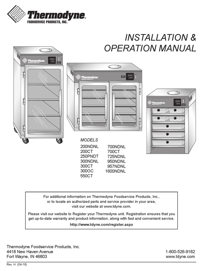
MODELS
125OC
200NDNL
200CT
250PNDT
300NDNL
300CT
300OC
550CT
700NDNL
700CT
725NDNL
950NDNL
957NDNL
1600NDNL

— 2 —
IMPORTANT FOR YOUR SAFETY
WARNING
IMPROPERINSTALLATION,ADJUSTMENT,ALTERATION,
SERVICE OR MAINTENANCE CAN CAUSE PROPERTY
DAMAGE, INJURY OR DEATH. READ THE
INSTALLATION, OPERATING AND MAINTENANCE
INSTRUCTIONS THOROUGHLY BEFORE INSTALLING
OR SERVICING THIS EQUIPMENT. SERVICE
WORK SHOULD BE PERFORMED BY A LICENSED
PROFESSIONAL,QUALIFIEDTOSERVICEANDREPAIR
ELECTRIC FOOD SERVICE EQUIPMENT.
IN THE EVENT OF A POWER FAILURE,
DO NOT ATTEMPT TO OPERATE THIS DEVICE.
CAUTION
Models 200 CT, 300 CT, and 700 CT have glass doors.
Remove carton carefully.

— 3 —
TABLE OF CONTENTS
IMPORTANT FOR YOUR SAFETY...................................................................................................2
INTRODUCTION...............................................................................................................................4
GENERAL....................................................................................................................................4
SPECIFICATIONS .......................................................................................................................4
UNPACKING..............................................................................................................................10
Thermodyne Damaged Goods Policy..................................................................................10
INSTALLATION CODES AND STANDARDS ............................................................................10
INSTALLATION..........................................................................................................................10
LOCATION.................................................................................................................................11
ELECTRICAL CONNECTION ...................................................................................................11
OPERATION....................................................................................................................................12
TEMPERATURE CONTROLLER SET UP PROCEDURES .................................................12
Keypad Operation................................................................................................................12
Set-Up..................................................................................................................................12
To Toggle Between °F and °C Readout ...............................................................................12
Preheating ...........................................................................................................................12
Extended Shutdown.............................................................................................................12
FLUID REPLENISHMENT.........................................................................................................13
PRODUCT PANS AND COVERS....................................................................................................14
GENERAL..................................................................................................................................14
Dry Pan Without Pan Screen...............................................................................................14
Dry Pan With Pan Screen....................................................................................................14
Wet Pan With Pan Screen...................................................................................................15
Pans With “V” Rack .............................................................................................................15
Removing Lids.....................................................................................................................16
CLEANING AND MAINTENANCE...................................................................................................17
WHEN TO CLEAN ...................................................................................................................17
HOW TO CLEAN......................................................................................................................17
Cleaning Safeguards ...........................................................................................................17
Sterilizing Stainless Steel ....................................................................................................17
Cleaning Heat Transfer Plates.............................................................................................17
Stainless Steel Cabinet........................................................................................................18
Door Gasket (CT Units) .......................................................................................................18
CHANGING FLUID....................................................................................................................18
TROUBLESHOOTING ....................................................................................................................20
SCHEMATIC DIAGRAM..................................................................................................................21
WARRANTY ....................................................................................................................................22
HEAT TRANSFER FLUID MSDS ....................................................................................................22

— 4 —
INTRODUCTION
GENERAL
Thermodyne cabinets are produced with quality
workmanship and materials. Proper installation,
operation and maintenance will result in many
years of satisfactory performance. It is suggested
that you thoroughly read this manual in its entirety
and carefully follow all of the instructions provided.
The cabinets described in this manual are
programmable for the desired holding temperature.
The factory setting is 185° F unless otherwise
specied. Each shelf in the cabinet maintains an
exact temperature, allowing for extended holding
times without sacricing appearance or taste.
MODEL
GALLONS LITERS PER SHELF
(OZ)
125OC 1.5 3.78 14
200NDNL 1.75 6.62 6
200CT 1.75 6.62 6
250OC 1.65 6.62 20
250PNDT 2.1 7.95 6
BW3 1.65 6.25 6
BW4 1.7 6.44 6
300NDNL 1.91 7.23 6
300CT 1.91 7.23 6
550CT 1.7 6.45 6
700NDNL 2.25 8.52 14
700CT 2.25 8.52 14
950NDNL 2.16 8.18 20
300OC 2.24 8.48 14
FLUID CAPACITIES (STANDARD SHELF CONFIGURATION)
MODEL
GALLONS LITERS PER SHELF
(OZ)
1200G 2.22 8.40 13
1200DW 2.3 8.71 14
1300G 2.32 8.78 13
1600NDNL 2.1 7.95 6
1900G 3.02 11.43 13
1900DW 3.06 11.58 14
2100DW 3.59 13.59 20
6000P 4.95 18.74 23.8
700DP 2.25 8.52 14
1500DP 3.01 11.39 14
742HW 2.45 9.27 14
744HW 3 11.36 28
1600HZ 2.5 9.46 Top-14;
Bottom-6
MODEL
DIMENSIONS AND MAXIMUM TEMPERATURE WEIGHT
Ext.
Width
inches
Ext.
Depth
inches
Ext.
Height
inches
Int.
Width
inches
Int.
Depth
inches
Int.
Height
inches
Max
Oper.
Temp °F
Max
Oper.
Temp °C
Net
Weight
lbs
Shipping
Weight
lbs
125OC 46.0 13.75 5.63 42.0 12.0 4.63 230 110 96 160
200NDNL 17.5 23.0 18.6 13.5 22.0 13.0 230 110 102 155
300NDNL 17.5 23.0 25.9 13.5 22.0 20.3 230 110 123 185
700NDNL 30.5 23.0 27.3 26.5 22.0 20.3 230 110 173 233
725NDNL 30.5 23.0 28.5 26.5 22.0 21.5 230 110 188 248
950NDNL 45.0 23.0 20.0 41.0 22.0 13.0 230 110 170 310
957NDNL 45.0 23.0 27.25 41.0 22.0 20.3 230 110 220 360
1600NDNL 17.5 33.0 61.8 13.5 22.0 49.6 230 110 241 405
200CT 17.5 24.8 20.0 13.5 22.0 13.0 230 110 103 160
300CT 17.5 24.8 27.3 13.5 22.0 20.3 230 110 126 190
550CT 17.5 24.8 41.4 13.5 22.0 29.4 230 110 190 230
700CT 30.5 24.8 27.3 26.5 22.0 20.3 230 110 189 265
300OC 59.0 13.5 14.6 55.0 12.5 9.0 230 110 160 235
250PNDT 21.3 20.0 33.3 17.3 19.0 27.6 230 110 168 203

— 5 —
FRONT VIEW SIDE VIEW PLAN VIEW
17 1/2"
Ext. Width
13"
Int.
Height
18 5/8"
Ext.
Height
1/8"
Base
13 1/2"
Int. Width
23"
Ext. Depth
2 1/8"
5 1/2"
P.H.
22"
Int. Depth
Thermodyne
Electrical
Front
1"
Cord & Plug
6 1/8"
10 1/2"
Figure 1. Outline Dimensional Drawing, 200NDNL
FRONT VIEW SIDE VIEW PLAN VIEW
17 1/2"
Ext. Width
13 1/2"
Int. Width
13"
Int.
Height
22"
Int. Depth
3 1/2"
Electrical
Front
1"
Cord & Plug
24 3/4"
Ext Depth
6 1/8"
10 1/2"
20"
Ext.
Height
Thermodyne
Figure 2. Outline Dimensional Drawing, 200CT
FRONT VIEW SIDE VIEW PLAN VIEW
17 1/2"
Ext. Width
20 1/4"
Int.
Height
25 7/8"
Ext.
Height
13 1/2"
Int. Width
1"
Front
Cord & Plug.
Thermodyne
23"
Ext. Depth
2 1/8"
10 1/2"
6 1/8"
5 1/2"
P.H.
1/8"
Base
22"
Int. Depth
Electrical
Figure 3. Outline Dimensional Drawing, 300NDNL

— 6 —
FRONT VIEW SIDE VIEW PLAN VIEW
17 1/2"
Ext. Width
20 1/4"
Int.
Height
27 1/4"
Ext.
Height
13 1/2"
Int. Width
1"
Front
Cord & Plug.
Thermodyne
24 3/4"
Ext. Depth
3 1/2"
10 1/2"
6 1/8"
22"
Int. Depth
Electrical
Figure 4. Outline Dimensional Drawing, 300CT
ADD FLUID
FRONT VIEW SIDE VIEW
59" Ext. Width
49 1/2"
17 1/2"
5 1/2"
Pan Covers 6 Pans Drip Pan
2 3/4"
3/4"
5 3/4"
7 5/8"
55" Int. Width 13 3/4"
Ext. Depth
12"
Int. Depth
5 5/8"
Ext. Heigth
4 5/8"
Int. Heigth
Ø3/8 × 60" SS
Flex Line
3 1/2"
25 7/8"
22"
Figure 5. Outline Dimensional Drawing, 125OC
FRONT VIEW
PLAN VIEW
SIDE VIEW
59" Ext. Width
9"
Int.
Height
14 5/8"
Ext.
Height
55" Int. Width
13 1/2"
Ext. Depth
12 1/2"
Int. Depth
Thermodyne
2 1/8"
Electrical
1"
Cord & Plug
6"
19"
Front
Figure 6. Outline Dimensional Drawing, 300OC

— 7 —
17 1/2"
13 1/2"
36 3/8" 29 3/8"
1 1/2"
5 1/2"
6"
10 3/8"
41 3/8"
24 3/4"
EXTERIOR WIDTH
INTERIOR WIDTH
INTERIOR
HEIGHT
EXTERIOR
HEIGHT
POWER HEAD
BASE
22"
INTERIOR DEPTH
EXTERIOR DEPTH
ELECTRICAL
ELECTRICAL
FRONT VIEW SIDE VIEW PLAN VIEW
Front
Figure 7. Outline Dimensional Drawing, 550CT
FRONT VIEW SIDE VIEW PLAN VIEW
20 1/4"
Int.
Height
30 1/2"
Ext. Width
27 14"
Ext.
Height
26 1/2"
Int. Width
Thermodyne
23"
Ext. Depth
2 1/8"
5 1/2"
P.H.
1 1/2"
Base
22"
Int. Depth
Electrical
1"
Front
Cord & Plug.
11 5/8"
11
1/2"
Figure 8. Outline Dimensional Drawing, 700NDNL
FRONT VIEW SIDE VIEW PLAN VIEW
20 1/4"
Int.
Height
30 1/2"
Ext. Width
27 1/4"
Ext.
Height
26 1/2"
Int. Width
Thermodyne
24 3/4"
Ext. Depth
3 1/2"
22"
Int. Depth
Electrical
1"
Front
Cord & Plug.
11 5/8"
11
1/2"
Figure 9. Outline Dimensional Drawing, 700CT

— 8 —
1"
Cord &
Plug
11
1/2"
Refill
11
5/8"
Refill
3 1/2"
Electrical
1 1/2"
Base
5 1/2"
P.H.
23"
Ext. Depth
22"
Int. Depth
30 1/2"
Ext. Width
28 1/2"
Ext. Height
21 1/2"
Int. Height
26 1/2"
Int. Width
FRONT VIEW SIDE VIEW PLAN VIEW
Thermodyne
Figure 10. Outline Dimensional Drawing, 725NDNL
FRONT VIEW SIDE VIEW PLAN VIEW
45" Ext. Width
41" Int. Width
2 1/2"
Cord &
Plug
Thermodyne
23" Ext. Depth
22" Int. Depth
5 1/2"
13"
Int.
Height
20"
Ext.
Height
1 1/2"
Base
1"
Cord & Plug
11 5/8"
25 7/8"
Front
Figure 11. Outline Dimensional Drawing, 950NDNL
FRONT VIEW SIDE VIEW PLAN VIEW
45" Ext. Width
41" Int. Width
2 1/2"
Cord &
Plug
Thermodyne
23" Ext. Depth
22" Int. Depth
5 1/2"
P.H.
20 1/4"
Int.
Height
27 1/4"
Ext.
Height
1 1/2"
Base
1"
Cord & Plug
11 5/8"
26"
Front
Figure 12. Outline Dimensional Drawing, 957NDNL

— 9 —
FRONT VIEW SIDE VIEW PLAN VIEW
1"
10"
Work
Area
Cord & Plug
20 1/4"
Upper
Int.
Height
29 3/8"
Lower
Int.
Height
17 1/2"
Ext. Width
61 3/4"
Ext.
Height
13 1/2"
Int. Width
Thermodyne
22"
Lower
Int. Depth
1/8"
Base
1
1/2"
Base
33"
Ext. Depth
5 12"
P.H.
22"
Int. Depth
Electrical
Front
6
1/8"
Figure 13. Outline Dimensional Drawing, 1600NDNL
FRONT VIEW SIDE VIEW PLAN VIEW
21 1/4"
Ext. Width
27 5/8"
Int.
Height
1/8"
Base
17 1/4"
Int. Width
20"
Ext. Depth
2 1/8"
5 1/2"
P.H.
19"
Int. Depth
Thermodyne
Electrical
Front
33 1/4"
Int.
Height
8 3/4"
3 7/8"
1 1/8"
Electrical
Figure 14. Outline Dimensional Drawing, 250PNDT

— 10 —
UNPACKING
NOTE: All Thermodyne cabinets are factory tested
for performance and certied free from
defects.
Thermodyne Damaged Goods Policy
There are two types of damaged merchandise:
A.Visible Damage and B. Concealed Damage.
A. Visible Damage: The product being received
is visibly damaged.
1. The receiver should refuse the damaged
merchandise.
2. Receiver should sign the bill of lading indicating
which merchandise is being refused due to
damage.
3. Contact Thermodyne Customer Service
Representatives immediately.
B. Concealed Damage: Damaged merchandise
cannot be externally detected.
Your receiving operation should inspect for this type
of damage. Please inspect your delivery carefully.
If the product is damaged:
1. Save all packing material.
2. Contact Thermodyne Customer Service
Representatives immediately.
3. Receiver must call the carrier to schedule an
inspection of the damaged merchandise within
5 business days.
INSTALLATION CODES
AND STANDARDS
In the United States, the Thermodyne cabinet
must be installed in accordance with:
1. State and local codes.
2. National Electrical Code (ANSI/NFPA No. 70,
latest edition) available from the National Fire
Protection Association, Batterymarch Park,
Quincy, MA 02269.
In Canada, the cabinet must be installed in
accordance with:
1. Local codes.
2. Canadian Electrical Code (CSA C22.2 No. 3,
latest edition) available from the Canadian
Standards Association, 5060 Spectrum Way,
Mississauga, Ontario, Canada L4W 5N6.
INSTALLATION
Before installing, verify the required electrical
supply agrees with the specications on the data
plate located on the back or side of the unit. If
the supply and equipment requirements do not
agree, do not proceed with installation. Contact
your dealer or Thermodyne Foodservice Products,
Inc. immediately.
CAUTION
Models 200CT, 300CT, 550CT and 700CT
have glass doors. Remove carton carefully.
CAUTION
Packaging may have sharp edges and
banding; leather work gloves and safety
glasses are recommended for safe
unpacking.
1. Allow ample overhead clearance for removal
of carton.
2. Cut banding (2 pieces) and remove nails (not
for all units).
3. To remove cabinet from carton, slide carton
up and o the cabinet.
4. Check packing list against items received:
A. Thermodyne Heat Transfer Fluid.
B. Installation & Operation Manual
5. Use proper lifting equipment to raise the
cabinet.
6. Remove the plastic covering from glass door
frames and hinges. Mount doors on cabinet,
then check doors for alignment (on certain
models).
7. Set cabinet on a level surface.

— 11 —
LOCATION
Allow adequate space for electrical connections.
The electrical cord and plug are located at the right
rear of the unit. The minimum clearance for proper
air circulation on back should be 4", and 2" on at
least one side. Allow adequate access space for
operating and servicing the unit.
NOTICE; Louvers on the sides of the oven
are used to circulate cool air throughout the
electrical components. The unit must not be
placed where extensive airborne grease is
present, such as near deep fryers or griddles.
ELECTRICAL CONNECTION
WARNING
ELECTRICAL AND GROUNDING
CONNECTIONS MUST COMPLY WITH
APPLICABLE PORTIONS OF THE
NATIONAL ELECTRICAL CODE AND/OR
OTHER LOCAL ELECTRICAL CODES.
WARNING
DISCONNECT THE ELECTRICAL POWER
TO THE THERMODYNE UNIT
AND FOLLOW LOCKOUT/TAGOUT
PROCEDURES.
Refer to the wiring diagrams in this manual for
wiring information.
MODEL VOLTS HERTZ PHASE WATTS AMPS PLUG TYPE US PLUG TYPE CAN
200NDNL 120 60 1 1750 15 NEMA 5-15P NEMA 5-20P
300NDNL 120 60 1 1750 15 NEMA 5-15P NEMA 5-20P
700NDNL 208/240 60 1 5250/7000 25/29 NEMA L14-30 —
725NDNL 208/240 60 1 5250/7000 25/29 NEMA L14-30 —
950NDNL 208/240 60 1 5250/7000 25/29 NEMA L14-30 —
957NDNL 208/240 60 1 5250/7000 25/29 NEMA L14-30 —
1600NDNL 208/240 60 1 5250/7000 25/29 NEMA L14-30 —
200CT 120 60 1 1750 15 NEMA 5-15P NEMA 5-20P
300CT 120 60 1 1750 15 NEMA 5-15P NEMA 5-20P
550CT 120 60 1 1750 15 NEMA 5-15P NEMA 5-20P
700CT 208/240 60 1 5250/7000 25/29 NEMA L14-30 —
300OC 120 60 1 1750 15 NEMA 5-15P NEMA 5-20P
250PNDT 208/240 60 1 5250/7000 25/29 NEMA L14-30 —

— 12 —
OPERATION
TEMPERATURE CONTROLLER
SET UP PROCEDURES
Output 1
Indicator
Process
Unit
Indicator
(°C on top,
°F on bottom)
Lower
Display:
To display
set point
value,
parameter
value,
control
output
value, etc.
Upper Display:
To display process value,
menu symbol, error code, etc.
Scroll
Key
Output 2
Indicator
Alarm
Indicator
Manual
Mode
Indicator
Auto-Tuning
Indicator
Up
Key
Down
Key
Return/Reset
Key
Figure 15: Controller
Keypad Operation
Scroll Key:
This key is used to select a parameter to be viewed
or adjusted.
Up Key:
This key is used to increase the value of the
selected parameter.
Down Key:
This key is used to decrease the value of the
parameter.
Return / Reset Key: R
This key is used to:
1. Return the display to indicate the Process
Value (PV) and Set Value (SV).
2. Reset a Latching Alarm once the alarm
condition has cleared.
3. Discontinue Manual Control,Auto-Tuning and
Calibration Modes.
4. Clear error messages indicating
communication and auto-tuning errors.
5. Re-set the dwell timer function.
6. Enter the manual control menu if the sensor
has failed.
Set-Up
1. Press the “Up” and “Down” key as needed to
adjust the displayed set-point temperature.
2. The “OUT1” LED will be lit up solid during
warm up. (normal operation)
3. When the “OUT1” LED is blinking, the unit has
reached the desired temperature.
NOTE: This controller is not an indicator of uid
level in the Heater or Reservoir Tanks.
To Toggle Between °F and °C Readout:
1. Press the “Scroll” key 2 -3 times until the upper
display reads: “unit”.
2. Press the “Up” or “Down” key to choose.
Preheating
Preheat the Thermodyne cabinet when rst used
for the day or whenever the unit is cold. Preheating
takes approximately 30 minutes at which time the
temperature set point and the actual temperature
will display the same temperature. If the cabinet
has door(s), keep the doors closed during the
preheat cycle.
Extended Shutdown
1. Press Power ON/OFF Switch to OFF position.
2. Clean pans and shelves.

— 13 —
FLUID REPLENISHMENT
CAUTION
Use only supplied Thermodyne Heat
Transfer Fluid.
1. Remove 1 screw securing the ll cap cover
and turn cover 180°.
2. Remove the reservoir tank cap.
3. Fill reservoir tank until ADD FLUID light
turns off.
4. Re-install the reservoir tank cap, pivot the ll
cap cover and replace the screw.
Reservoir
Tank
Reservoir Tank
Cap
Fill Cap
Cover
Figure 16. Reservoir Tank Replenishment
NOTE: If the ADD FLUID Light remains on after
the Thermodyne unit has been lled, refer
to TROUBLESHOOTING.

— 14 —
GENERAL
NOTE: Food products can be held dry, moist,
assembled, and wrapped.
Dry Pan Without Pan Screen
Figure 17. Dry Pan Without Pan Screen
Used for products with high moisture, such as:
Sauces
Gravies
Casseroles
All products with fast turnover
Breaded Products – Vented/No Moisture
Ribs and Riblets
Potatoes
Scrambled Eggs
Vegetables
For crispier products, hold uncovered or vented.
Uncovered product should have an optional solid
back.
Dry Pan With Pan Screen
Figure 18. Dry Pan With Pan Screen
Used for dry and crisp products. Ideal for products
with high oil content, such as:
Bacon
Hot Dogs
Hamburger Patties
Breaded Chicken Patties
Biscuits
English Muns
Fried Fish
Fried Chicken – Vented or No Cover
Fried Sandwiches – Vented or No Cover
French Toast
PRODUCT PANS AND COVERS

— 15 —
Wet Pan With Pan Screen
Insert stainless steel insert rack; pour in water
prior to adding food product. Water will typically
last for several hours, but will vary by temperature
setting. Never allow water to sit overnight.
Figure 19. Wet Pan With Pan Screen
Used for products susceptible to drying, such as:
Grilled Chicken Breast
Egg Products for Sandwiches, Sausage Links,
and Patties
Hamburger Patties (extended holding)
Bagels
Pancakes
Assembled Wrapped Sandwiches
Pans With “V” Rack
Water can be added to the bottom of the pan for
moisture.
Figure 20. Pans With “V” Rack
Used for products such as:
Tacos
Burritos
Assembled Hot Dogs
Small Wrapped Sandwiches
Hot Spring Rolls

— 16 —
Removing Lids
CAUTION
Lid may be extremely hot.
CAUTION
Handle with care; lids may have sharp
edges.
Out 1
Out 2
Alm 1
MAN
°C
°F
A/T
ADD FLUID
Figure 21. Removable Lid
1. Remove lid by taking out the pans and lifting
up on the metal lid. Lids can then be cleaned
and sanitized.
2. When changing pans to different food
products, lids should be cleaned to avoid cross
contamination of food product or migration of
avors.

— 17 —
CLEANING AND MAINTENANCE
WARNING
DISCONNECT ELECTRICAL POWER TO
THE THERMODYNE UNIT AND FOLLOW
LOCKOUT/TAGOUT PROCEDURES
BEFORE CLEANING.
CAUTION
Stainless steel lids may have sharp edges;
handle with extreme care while cleaning.
WHEN TO CLEAN
It is recommended that all stainless steel
equipment be cleaned on a regular basis. Any
piece of stainless steel equipment that is soiled
should be cleaned daily to ensure the long life of
the equipment. Routine cleaning will also lessen
stainless steel abrasion.
HOW TO CLEAN
To remove most soil, use a non-abrasive, non-
chlorinated soap solution. Rinse thoroughly with
warm water and wipe dry using an absorbent
cloth. To remove heavy soil, rub the area with a
non-metallic, ne-grain scouring cloth. Be sure to
rub in the same direction as the metal grain. Rinse
thoroughly with warm water and wipe using a soft
absorbent cloth. As a nal step, a stainless steel
polish may be applied. The polish will shine the
stainless steel and provide a protective nish to
reduce future soiling.
Cleaning Safeguards
1. Always rub in the direction of the metal grain.
Never use steel wool or metallic scouring
cloths. These two measures will help prevent
scratching and possible damage to the
surface nish.
2. Use the recommended dilution. Do not exceed
concentration levels as this may cause long
term deterioration of the surface. Be certain
to rinse surface thoroughly to prevent buildup
of cleanser.
3. Never use chlorine or bleach solutions.
Check the ingredients of cleaning solutions
or disinfectants used as they may contain
chlorinated solvents.
4. Always read the label of the cleaning
solutions. Check for warnings about use
on stainless steel or aluminum products.
Repeated use of chlorinated solvents may
cause a chemical reaction with stainless
steel or aluminum; resulting in damage to
the surface and rusting.
Sterilizing Stainless Steel
When sterilizing stainless steel equipment, pay
particular attention to agents containing chlorine
compounds such as potassium hypochlorite. These
compounds may break down and release free
chlorine or hydrolyze to form hydrochloric acid.
Stainless steel can resist attack by the compounds
for up to 2 hours. Severe localized pitting may
occur with longer exposure. For safe use of the
agents, keep contact time short, ush thoroughly
with water, and operate equipment normally
between applications. Using these precautions,
the sterilization process can be repeated as often
as necessary.
Cleaning Heat Transfer Plates
The Thermodyne unit operates on the principle
of conduction, rather than convection. Therefore,
it is very important to keep the heat transfer
shelves clean, so heat transfer may take place
with maximum eciency. It is also very important
to keep the bottom contact surfaces of pots and
pans as clean as possible to ensure even and
complete heat transfer.
The surface and at coating of the thermal heat
transfer shelf is extremely hard, but will react with
strong caustic cleaning solutions and deteriorate.
CAUTION
Most concentrated soaps and ammonia
cleaners are too caustic to be used on the
Thermodyne unit.

— 18 —
If the coating is destroyed, the heat transfer
shelves will lose their non-stick properties and
their surface hardness.
The cleaners should always be used at the
recommended concentrations. In the case of dry
powders, the powders must not be placed directly
on the surface of the heat transfer plate. Care
must be taken not to scratch the shelf surfaces
when using brushes or pads. If harsh scouring is
needed, use a nylon type scouring pad. Never
use steel wool.
It is recommended that a weekly cleaning schedule
be followed to avoid the buildup of heavy food
product deposits. In the event heavy deposits
occur that are dicult to remove with ordinary
cleaning procedures, stronger chemical cleaning
agents may be applied if the products are intended
for food service use and are also compatible with
hard coat anodized aluminum surfaces. When
using these stronger solvents, it is very important
that heat transfer shelves are rinsed thoroughly
with clean potable water after cleaning. Be sure to
remove all traces of the cleaning agent. Between
the regular scheduled cleaning, wipe o the
anodized aluminum surfaces periodically with a
clean damp cloth.
Stainless Steel Cabinet
1. Any pot and pan detergent acceptable for food
service cleaning and compatible with aluminum
and stainless steel may be used on shelf and
cabinet surfaces.
2. A #20 plastic bristled brush used with the
appropriate detergent is acceptable for
cleaning. It is very important when cleaning
the heat transfer shelves that the undersides
of the shelves are thoroughly cleaned also.
3. Hot water hose rinsing is preferred. If a hose
is not available, rinsing with a sponge or cloth
and clean hot water is acceptable. Be sure
all surfaces are completely rinsed during the
rinsing procedure. Do not allow water to come
in contact with the Powerhead located on the
top of the Thermodyne unit.
4. The glass doors can be cleaned with any
commercial window-cleaning product,
provided they are free of ammonia or chlorine
and are food service compatible.
Door Gasket (CT Units)
Clean the gasket-sealing surface of the
Thermodyne doors to remove food product acids
for maximum gasket life. Do not use any solvents
or sharp instruments as these will damage the
gasket. Wash with a cloth moistened in a solution
of mild detergent and warm water. Rinse with a
fresh cloth moistened with warm water to remove
all traces of detergent.
Wipe dry with a clean cloth. Never apply food
product oils or petroleum lubricants directly to
the door gasket as these will reduce gasket life.
CHANGING FLUID
NOTE: The Thermodyne Heat Transfer Fluid
has lubricating additives, anticorrosion
additives, and heat transfer properties
that may decrease with the passing of
time. Thermodyne Heat Transfer Fluid
will protect the unit indenitely if the uid
is changed on an annual basis.
CAUTION
The following procedure is to be performed
by a qualied service technician only.
WARNING
DISCONNECT THE ELECTRICAL
POWER TO THE THERMODYNE UNIT
AND FOLLOW LOCKOUT/TAGOUT
PROCEDURES.
1. Disconnect the unit from its power source and
allow the unit to cool completely.
2. Remove the stainless steel panel covering the
left side of the unit.
3. Remove the powerhead lid; 4 screws.

— 19 —
Powerhead
Lid
Heater
Tank
Out 1
Out 2
Alm 1
MAN
C
F
A/T
ADDFLUID
Figure 22. Powerhead Lid
4. Place a pan or bucket beside drain plug in
order to catch drained uid.
Supply Rail
Drain
Hose
Drain
Plug
Figure 23. Drain Hose
5. Aim drain hose into pan or bucket and turn
valve to open position.
Heater
Tank
Heater Tank
Cap
Out 1
Out 2
Alm 1
MAN
°C
°F
A/T
ADDFLUID
Figure 24. Heater Tank Cap
6. Locate heater tank and remove cap.
7. Once oven has drained completely turn valve
to o position and place drain hose back in
cabinet.
8. Return stainless steel panel to left side.
9. Rell the unit with Thermodyne Heat Transfer
Fluid only. Never substitute with water or other
liquids.
10. Return heater tank cap.
11. Place lid back on, but do not tighten screws.
12. Plug unit in and turn on.
13. Unit will run briey and shut o due to low uid
level.
14. Remove powerhead lid and heater tank cap
and ll heater tank.
Heater Tank
Heater Tank Cap
Figure 25. Heater Tank Fill
15. Repeat steps 11-15 until unit is completely full
of uid.
16. Once unit is completely lled, place power-
head lid back on unit and tighten screws snug.
17. If ADD FLUID light is on, add uid to reservoir
tank until light goes out.
18. Let unit run until maximum temperature is
reached.
19. Once full temperature is reached, shut unit
down and let it cool down to at least 100°F.
20. Turn unit back on, and if ADD FLUID light is
on again, continue adding uid to reservoir
tank until light goes out.
NOTE: Steps 19 and 20 are very critical in order
to purge oven from any air trapped in unit.

— 20 —
TROUBLESHOOTING
Most problems associated with the holding unit are due to low uid level. Always check uid level rst.
*Recommended to be done by a qualied service agency.
NOTE: Most problems associated with the Thermodyne cabinet are due to failure to add Thermodyne
Heat Transfer Fluid. Check uid level rst. In the event service is required on your Thermodyne
Oven, please call: (800) 526-9182.
PROBLEM POSSIBLE CAUSE SOLUTION
No Power:
1. Main power switch o.
2. Not plugged in.
3. Breaker o or tripped.
4. Bad contactor.
1. Turn switch on.
2. Check plug.
3. Check breaker.
4. Replace contactor.*
LOW FLUID light is on -
Oven heating properly:
1. Oven is low on uid. 1. Add Thermodyne Heat Transfer Fluid
per instructions.
LOW FLUID light is on -
Oven not heating
properly:
1. Oven disabled due to low uid level
cut out.
2. Fluid level probe defective.
3. System leak.
1. Main heater tanks low on uid. Add
Thermodyne Heat Transfer Fluid and
determine cause of uid loss.
2. Repair or replace.*
3. Repair leak.*
Heater(s) not working:
1. Unit not properly wired.
2. Bad heater(s).
3. Contactor or solid state relays not
working.
4. O due to low uid cut out.
5. Failed temperature controller.
6. High limit snap disc tripped.
1. Check wiring.*
2. Replace heater(s).*
3. Repair or replace.*
4. Add Thermodyne Heat Transfer Fluid
per instructions.
5. Replace temperature controller.*
6. Reset snap disc and check for cause.*
Shelves hotter than set
point:
1. Temperature controller out of
calibration.
2. Thermocouple defective.
3. Solid state relay(s) stuck on.
4. Failed temperature controller.
1. Recalibrate temperature controller. *
2. Replace thermocouple.*
3. Replace solid state relay(s).*
4. Replace temperature controller.*
Shelves colder than set
point:
1. Low uid in tank. (LOW FLUID light
should be lit)
2. Failed temperature controller.
3. Heater(s) not working.
4. Pump failure.
5. Thermocouple failure.
1. Add Thermodyne Heat Transfer Fluid
per instructions.
2. Replace temperature controller.*
3. See “Heater(s) not working”.
4. Repair or replace pump.
5. Replace thermocouple.*
Oven heats up too slow: 1. Heater(s) not working. 1. See “Heater(s) not working”.
This manual suits for next models
13
Table of contents
Other THERMODYNE Oven manuals
Popular Oven manuals by other brands
Aroma
Aroma ABT-208S Instruction manual & recipe guide
Elba
Elba EBO-N6770 owner's manual
Signature Kitchen Suite
Signature Kitchen Suite SKSLV2401S owner's manual
Officine Gullo
Officine Gullo FES8EMU Instructions for installation and use
AEG
AEG Competence B 2100 operating instructions
Siemens
Siemens HB78AB 90B Series instruction manual
