THERMODYNE 2600DP User manual

INSTALLATION &
OPERATION MANUAL
(11-13)
MODEL
2600DP
Thermodyne Foodservice Products, Inc.
4418 New Haven Avenue 1-800-526-9182
Fort Wayne, IN 46803 www.tdyne.com
For additional information on Thermodyne Foodservice Products, Inc.,
or to locate an authorized parts and service provider in your area,
visit our website at www.tdyne.com.
Please visit our website to Register your Thermodyne unit. Registration ensures that you
get up-to-date warranty and product information, along with fast and convenient service.
http://www.tdyne.com/register.aspx
— 2 —
IMPORTANT FOR YOUR SAFETY
THIS MANUAL HAS BEEN PREPARED FOR PERSONNEL QUALIFIED TO INSTALL ELECTRICAL
EQUIPMENT, WHO SHOULD PERFORM THE INITIAL FIELD STARTUP AND ADJUSTMENTS OF
THE EQUIPMENT COVERED BY THIS MANUAL.
READ THIS MANUAL THOROUGHLY BEFORE OPERATING, INSTALLING OR PERFORMING
MAINTENANCE ON THE EQUIPMENT.
: Failure to follow all the instructions in this manual can cause property damage,
injury or death.
: Improper installation, adjustment, alteration, service or maintenance can cause
property damage, injury or death.
: Electrical connections should be performed only by a certied professional.
: Electrical and grounding connections must comply with the applicable portions
of the National Electric Code and/or all local electric codes. Failure to comply with this
procedure can cause property damage, injury or death.
: Before connecting the unit to the electrical supply, verify that the electrical and
grounding connections comply with the applicable portions of the National Electric Code and/or
other local electrical codes. Failure to comply with this procedure can cause property damage,
injury or death.
: Before connecting the unit to the electrical supply, verify that the electrical
connection agrees with the specications on the data plate. Failure to comply with this
procedure can cause property damage, injury or death.
: UL73 grounding instructions: This appliance must be connected to a grounded,
metal, permanent wiring system. Or an equipment-grounding conductor must be run with the
circuit conductors and connected to the equipment-grounding terminal or lead on the appliance.
Failure to comply with this procedure can cause property damage, injury or death.
: Appliances equipped with a exible electric supply cord, are provided with
a three-prong grounding plug. It is imperative that this plug be connected into a properly
grounded three-prong receptacle. Failure to comply with this procedure can cause property
damage, injury or death.
: If the receptacle is not the proper grounding type, contact an electrician. Do not
remove the grounding prong from the plug. Failure to comply with this procedure can cause
property damage, injury or death.
: Before performing any service that involves electrical connection or
disconnection and/or exposure to electrical components, always perform the Electrical
LOCKOUT/TAGOUT Procedure. Disconnect all circuits. Failure to comply with this procedure
can cause property damage, injury or death.

— 3 —
: Before removing any sheet metal panels or servicing this equipment, always
perform the Electrical LOCKOUT/TAGOUT Procedure. Be sure all circuits are disconnected.
Failure to comply with this procedure can cause property damage, injury or death.
: Do not operate this equipment without properly placing and securing all covers
and access panels. Failure to comply with this procedure can cause property damage, injury or
death.
: Do not use or store gasoline or other ammable vapors or liquids in the vicinity
of this or any other appliance. Failure to comply can cause property damage, injury or death.
: In the event of a power failure, do not attempt to operate this appliance. Failure
to comply can cause property damage, injury or death.
CAUTION: These models have glass doors. Remove carton carefully.
FOR YOUR SAFETY
DO NOT STORE OR USE GASOLINE OR OTHER FLAMMABLE
VAPORS OR LIQUIDS IN THE VICINITY OF THIS OR ANY OTHER
APPLIANCE. FAILURE TO COMPLY CAN CAUSE PROPERTY
DAMAGE, INJURY OR DEATH.

— 4 —
TABLE OF CONTENTS
IMPORTANT FOR YOUR SAFETY...................................................................................................2
FOR YOUR SAFETY...................................................................................................................3
INTRODUCTION .........................................................................................................................5
GENERAL....................................................................................................................................5
SPECIFICATIONS .......................................................................................................................5
DIMENSIONS AND MAXIMUM TEMPERATURE .......................................................................5
FluidCapacities(StandardShelfConguration)....................................................................5
WEIGHT ......................................................................................................................................5
UNPACKING................................................................................................................................7
Thermodyne Damaged Goods Policy....................................................................................7
INSTALLATION CODES AND STANDARDS ..............................................................................7
INSTALLATION .................................................................................................................................8
LOCATION...................................................................................................................................8
ELECTRICAL CONNECTION .....................................................................................................8
ELECTRICAL SPECIFICATIONS................................................................................................8
OPERATION......................................................................................................................................9
CABINET STARTUP....................................................................................................................9
HOT WELL CONTROLS AND INDICATORS ............................................................................13
HOT WELL STARTUP ...............................................................................................................14
Setting Temperature ............................................................................................................14
Preheating ...........................................................................................................................14
CLEANING AND MAINTENANCE...................................................................................................15
ELECTRICAL LOCKOUT/TAGOUT PROCEDURE...................................................................15
WHEN TO CLEAN.....................................................................................................................15
STAINLESS STEEL CARE........................................................................................................15
Cleaning...............................................................................................................................15
Preserving & Restoring........................................................................................................15
Heat Tint ..............................................................................................................................16
CLEANING HEAT TRANSFER PLATES ...................................................................................16
CLEANING DOOR GASKETS ..................................................................................................16
FLUID REPLENISHMENT.........................................................................................................16
CHANGING FLUID....................................................................................................................17
TROUBLESHOOTING ....................................................................................................................19
SCHEMATIC WIRING DIAGRAM ...................................................................................................20
WARRANTY ....................................................................................................................................21
HEAT TRANSFER FLUID MSDS ....................................................................................................21

— 5 —
DIMENSIONS AND MAXIMUM TEMPERATURE
Model
Ext.
Width
inches
Ext.
Depth
inches
Ext.
Height
inches
Int.
Width
inches
Int.
Depth
inches
Int.
Height
inches
Max
Oper.
Temp
°
F
2600DP 87.38 40.38 39.50 13.5
each 21.50 27.50 230
WEIGHT
Model
Net
Weight
lbs
Shipping
Weight
lbs
2600DP 725 1000
SPECIFICATIONS
INTRODUCTION
GENERAL
Thermodyne cabinets are produced with quality
workmanship and materials. Proper installation,
operation and maintenance will result in many
years of satisfactory performance. It is suggested
that you thoroughly read this manual in its entirety
and carefully follow all of the instructions provided.
The cabinets described in this manual are
programmable for the desired holding temperature.
Each shelf in the cabinet maintains an exact
temperature, allowing for extended holding times
withoutsacricingappearanceortaste.
FLUID CAPACITIES
(STANDARD SHELF CONFIGURATION)
Model Gallons Liters
Per Shelf
(Oz)
2600DP 4.0 15.1 34.1 4-wire
NEMA L21-30P
30 amp
125/250V
X
Z
Y
G
W
PLUG
— 6 —
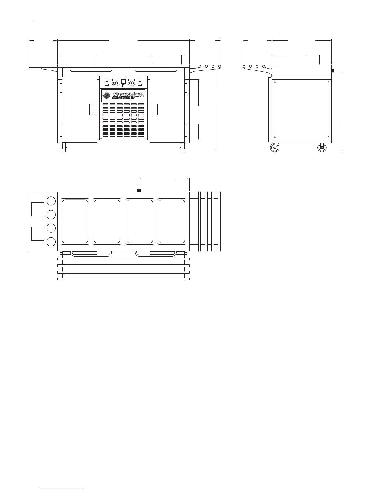
27-1/2
Interior
Height
39-1/2
Exterior
Height
14-3/8
Tray Slide
13-3/8
Tray Slide
13-1/2
Interior Width
21-1/2
Interior Depth
27
Exterior Depth
13-1/2
Interior Width
60
Exterior Width
13
Condiment
Shelf
23
Cord & Plug
37
Cord &
Plug
Figure 1: Outline Dimensional Drawing, 2600DP

— 7 —
UNPACKING
All Thermodyne cabinets are factory tested for
performanceandcertiedfreefromdefects.
Thermodyne Damaged Goods Policy
There are two types of damaged merchandise:
A. Visible Damage and B. Concealed Damage.
A. Visible Damage: The product being received
is visibly damaged.
1. The receiver should refuse the damaged
merchandise.
2. Receiver should sign the bill of lading
indicating which merchandise is being
refused due to damage.
3. Contact Thermodyne Customer Service
Representatives immediately.
B. Concealed Damage: Damaged merchandise
cannot be externally detected.
Your receiving operation should inspect for this
type of damage. Please inspect your delivery
carefully.
If the product is damaged:
1. Save all packing material.
2. Contact Thermodyne Customer Service
Representatives immediately.
3. Receiver must call the carrier to schedule
an inspection of the damaged merchandise
within 5 business days.
INSTALLATION CODES
AND STANDARDS
These installation instructions are for the use of
qualied installation and service personnel
only.
1. Installationorservicebyotherthanqualied
personnel may result in damage to the
Thermodyne cabinet and/or injury to the
operator.
2. National Electrical Code (ANSI/NFPA No. 70,
latest edition) available from the National Fire
Protection Association, Batterymarch Park,
Quincy, MA 02269.
In Canada, the cabinet must be installed in
accordance with:
1. Local codes.
2. Canadian Electrical Code (CSA C22.2 No. 3,
latest edition) available from the Canadian
Standards Association, 5060 Spectrum Way,
Mississauga, Ontario, Canada L4W 5N6.

— 8 —
INSTALLATION
Before installing, verify the required electrical supply
agrees with the specications on the data plate
located on the back or side of the unit. If the supply and
equipment requirementsdo notagree, do notproceed
with installation. Contact your dealer or Thermodyne
Foodservice Products, Inc. immediately.
CAUTION: These models may have glass
doors. Remove carton carefully.
1. Allow ample overhead clearance for removal
of carton.
2. Cut banding (2 pieces) and remove nails (not
for all units).
3. To remove cabinet from carton, slide carton
up and off the cabinet.
4. Check packing list against items received:
A. Thermodyne Heat Transfer Fluid
B. Installation & Operation Manual
C. 32 oz Fill Bottle
5. Use proper lifting equipment to raise the cabinet.
6. Remove the plastic covering from glass door
frames and hinges.
7. Mount doors on cabinet, and then check doors
for alignment.
8. Set cabinet on a level surface.
9. Plug in oven, let sit for 24 hours before putting
power switch to the on position.
10. Check all connections for leaking and make
sure the fans in the interior of the walls function
during the cooling cycle.
11. The Set Point Temperature will be reached in
approximately 30 minutes.
LOCATION
Allow adequate space for electrical connections.
The electrical cord and plug are located at the
right rear of the unit. The minimum clearance for
proper air circulation on back should be 4”, and
2” on at least one side. Allow adequate access
space for operating and servicing the unit.
NOTICE: Louvers on the sides of the oven
are used to circulate cool air throughout
the electrical components. The unit must
not be placed where extensive airborne
grease is present, such as near deep fryers
or griddles.
ELECTRICAL CONNECTION
: Electrical and grounding
connections must comply with applicable
portions of the National Electrical Code and/
or other local electrical codes.
: Disconnect the electrical
power to the Thermodyne unit and follow
LOCKOUT/TAGOUT procedures.
Refer to the wiring diagrams in this manual for
wiring information.
ELECTRICAL SPECIFICATIONS
Model Volts Amps Watts Hertz Phase Plug*
2600DO 125/250 24/27 8739/10740 50/60 3 NEMA L21-30P**
*Plugs are 4-wires with ground, 2 hot and neutral.
**Optional 110V 20 Amp plug for hold mode
CRATE FRONT VIEW CRATE SIDE VIEW
— 9 —
OPERATION
CABINET STARTUP
: The oven cabinet and hot
wells are hot. Use care when operating,
cleaning or servicing this equipment.
Once the cabinet is installed and electrical
connections have been made, thoroughly test the
Thermodyne cabinet before operation.
1. Check that all packing materials and other
items have been removed from the cabinet.
2. Press the Power ON/OFF Switches to the ON
position. The operating temperature will be
reached in approximately 30 minutes.
3. Check ADD FLUID Light.
If light remains on or ickers continuously
afterfteenminutes,addHeatTransferFluid.
Thermodyne recommends the heat transfer
uidbeaddedtoacoldunit(below45°F).
NOTE: If the oven is over-lled, uid will
escape from the vapor relief valve when the
oven heats up.
4. The controller readout will light up and indicate
thetemperatureoftheuidinthetank(notthe
food temperature) at present time.
• Cooling temperatures will be between
34–41°F.
• Heating cycles will have a maximum
temperatureof230°F.
• Holding cycles temperatures can be set
between160–210°F.
5. The operating temperature will be reached
in approximately 30 minutes. This time will
varyasthebeginninguidtemperatureand
operating temperature are varied.
6. To turn the oven off, turn the red power switch
to the OFF position.
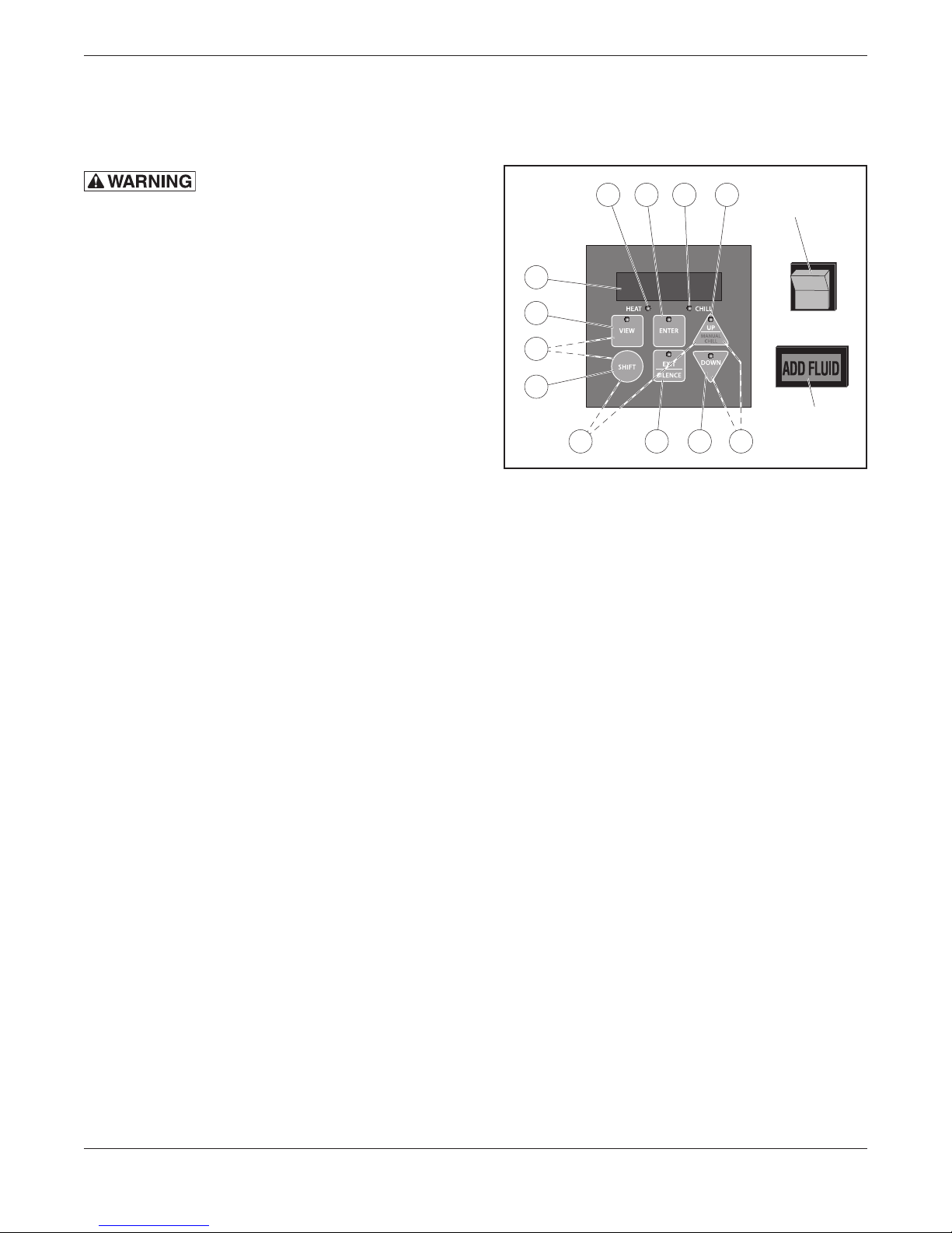
CABINET CONTROLLER PARTS
11 122 3
5 67 8
Power
Switch
Low Fluid
Indicator
Light
10
1
9
4
Figure 2: Cabinet Controller
1. VIEW key
Press once for time of day.
Press twice to view the time left in a heating
cycle or the amount of time it has been in a
hold cycle.
Press three times to view the next programmed
mealtime.
2. ENTER Key
Usedtoenter,orconrm,theconclusionof
changes to a mealtime setting.
3. UP Key (MANUAL CHILL when used with
SHIFT)
Used to increase, or scroll through the values
that can be set when programming the
Controller.
4. SHIFT key
Used in conjunction with the “UP/MANUAL
CHILL” key. ONLY while the unit is in the hold
cycle, pressing SHIFT and MANUAL CHILL
simultaneously will return the unit to the manual
chill mode.
5. EXIT / SILENCE Key
Used to exit programming without changing
previous settings.
Used to silence an audible alarm.
— 10 —
6. DOWN Key
Used to decrease settings, or scroll through
values when programming the controller.
7. Manual Chill Cycle
Pressing the “UP/MANUAL CHILL” key and
the “SHIFT” key at the same time and while
the unit is in a hold cycle will revert the unit to
its chill cycle.
8. Menu Program Password
Simultaneously pressing “UP” and “DOWN”
keys for 3 seconds sends the controller into the
programming menu where Enable, Retherm
duration, Retherm Temperature, Hold time,
Hold temperatures & Meal Times can be set.
9. Secondary Program Password
Simultaneously pressing the “VIEW” and
“SHIFT” keys for 3 seconds allows the unit
to be programmed with time of day and other
parameters.
10. Displays the Temperature
Thedisplayshowstheuidtemperaturethat
circulates through the oven
11. Heat indicator LED
When LED is solidly lit - Retherm Cycle; when
ashing-HoldCycle.
12. Chill indicator LED
When LED is solidly lit - Chill Mode.
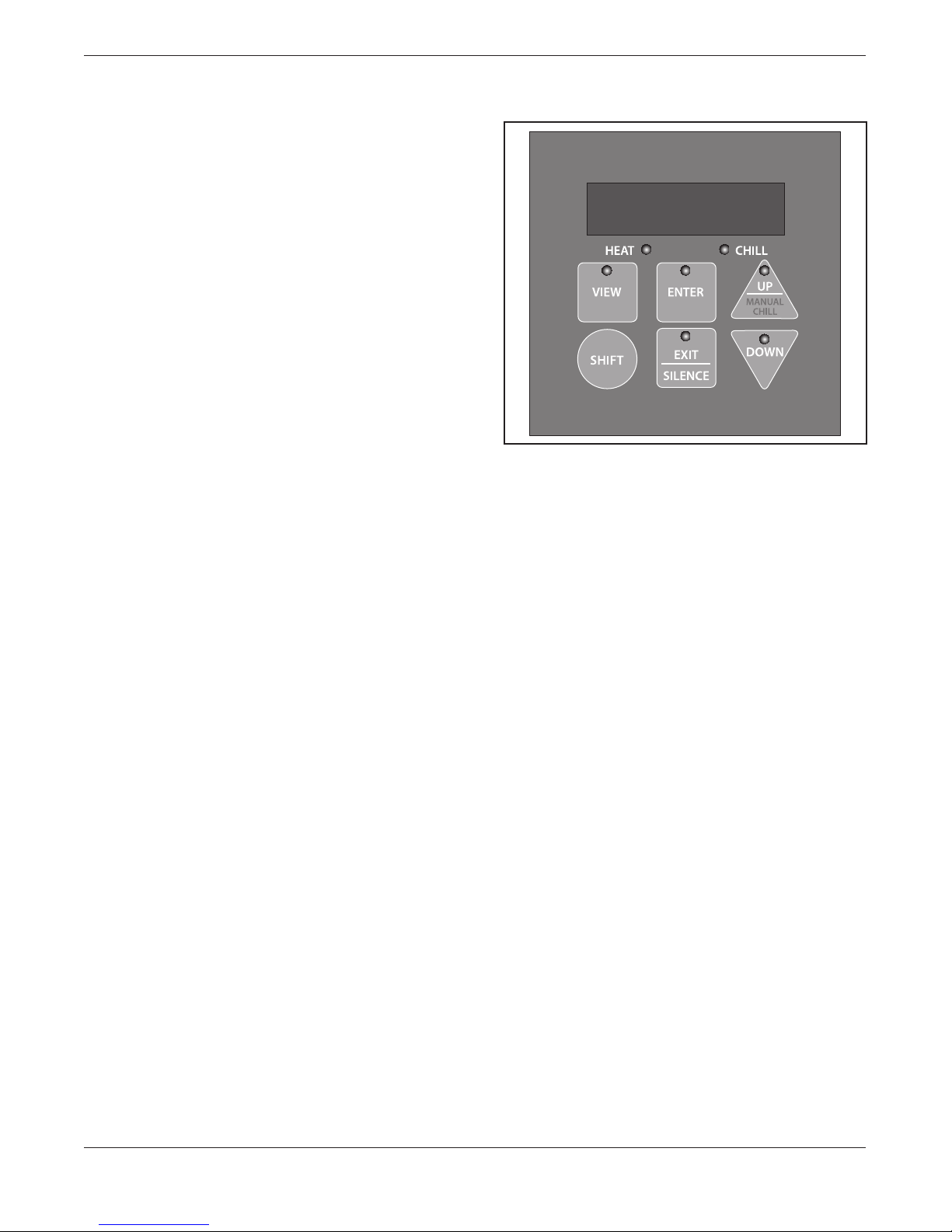
CABINET CONTROLLER SET-UP
Figure 3: Control Panel
Setting the Time of Day
1. Turn the Red Power Switch to “ON”
2. To view the “Time of Day” - Press the “VIEW”
button for 1-2 seconds.
3. SettingtheTimeofDay•Pressthe“VIEW”and
“SHIFT” keys simultaneously for 3 seconds.
• Thedisplaywillash“tod”andthetime,
alternately.
• Press “view” again and the time will be
displayed,butnotashing.
• Pressthe“UP”or“DOWN”keystochange
the time. Scroll to the correct time. (A
represents AM; P represents PM.)
• Oncethetimeiscorrect,pressthe“ENTER”
key to set the time.
• Press“ENTER”againtoconrmandleave
this programming stage. * DO NOT PRESS
the EXIT key, this will make the time revert to
the previous setting before it was changed.
* Like the “tod” parameter, users may wish
to change the settings for the temperature
scale,“°C_°F”;theendofrethermalarm,“r
Snd”; or the end of hold alarm “H Snd” at
this point by scrolling with the arrow keys
to the parameter prior to pressing “Enter”
for the second time.

— 11 —
The alarms have six settings, 0 through 5. The
following is an explanation of each setting:
0 = No alarm sound
1 = Alarm sounded for 2 seconds
2 = Alarm sound alternatives on/off every
second for 20 seconds
3 = 3 short beeps follow by 1 second off,
this cycle repeats itself for 20 seconds.
4 = Alarm sounds on/off every second
continuously
5 = Alarm is on solid, continuously
“r Snd” signals the end of retherm, and its
default value is 5.
“H Snd” indicates the end of the hold cycle,
and its default value is 0.
Programming
The following is the procedure that should be
followed when programming the controller. The
controller programming allows six functions for
each meal to be entered into the system.
They are:
Prompt Description Values
EnAbl Enable/Disable
menu number.
Range: Yes, No
Default: No
TinE1 Retherm Start
Time
Range:
A12:00,
P11:59, set in 1
min increments
Default: A09:00
TinE1
Retherm
Temperature
Setpoint
Range: 165to230°F,in
1°Fincrements
Default: 225°F
TinE1 Retherm
Duration
Range:
5 to 180
min, in 5 min
increments
Default: 120 min.
HStPt
Hold State
temperature
setpoint
Range: 160-210°F,in
1°Fincrements
Default: 160°F
Htine Duration of
Hold State
Range: 0 to 5 hrs, in 5
min increments
Default: 3 hrs.
To Enter Programming:
Whenenteringprogrammingforthersttime,each
meal 1-5 [(M1), (M2), (M3), (M4), (M5)] will have
the factory defaults entered for each parameter.
All Enable settings will be No, all holding times
will be 3:00 hours, all holding temperatures will
be160°F,allrethermingdurationswillbe2:00
hours,allrethermingtemperatureswillbe225°F
and all meal retherm times will be A-9:00 (9am).
1. Press the “UP” and “DOWN” and hold for 3
seconds until the “M1” characters appear. (Use
the arrows to scroll from M1 to M5.) Keep in
mind that if no programming keys are pressed
for one minute, the controller will automatically
exit to the normal operating mode.
Enable a Meal
To enable a meal, set a hold time duration, set a
hold temperature, set a retherm duration, set a
retherm temperature and set a meal time, follow
the following instructions:
2. Press “VIEW.” the screen will display - EnAbl
/no-thesetwowordswillashfromEnAblto
no appearing alternately on the screen. (no is
the factory preset).
3. Press “VIEW” again and the message will be
- no.
4. Press the “UP” key then yES will appear.
5. Press “ENTER” the screen will display - EnAbl
/yES-alternatelyashing.(amealhasbeen
enabled).
TO CONTINUE THROUGH THE
PROGRAMMING SCREENS PRESS THE “UP”
KEY. THE NEXT OPTION IS HOLDING TIME. -
(Proceed to Step 7)
6. To conrm and leave the programming for
Meal 1 (M1) stage, Press “ENTER” “ENTER”
- (ENTER 2 TIMES).
SET HOLDING TIME - Holding time range 0 min
to 3 hours
7. Press “UP” the screen will display - HtinE
/3:00– alternately ashing (HtinE - 3:00=
holding time 3 hours).

— 12 —
8. Press “VIEW” and the 3:00 will appear. (To
change the time to 2hr 40 min {for example}
proceed with steps 9 & 10.)
If three hours is desired and no changes are
necessary, press enter and proceed to the
next screen which is holding temperature.
9. Press the “DOWN” key 4 times and 2:40
will appear. (The key changes in 5 minute
increments ranging from 0 min to 3 hours).
10. Press “ENTER” and the screen will display -
HtinE/2:40-alternatelyashing(indicating
that the new holding time has been entered).
TO CONTINUE THROUGH THE
PROGRAMMING SCREENS PRESS THE
“UP” KEY THE NEXT OPTION IS HOLDING
TEMPERATURE. (Proceed to Step 12)
11.To conrm and leave the programming for
Meal 1 (M1) stage. Press “ENTER” “ENTER”
- (ENTER 2 TIMES).
SET HOLDING TEMPERATURE - Holding
temperaturerange160-210°F
12. Press “UP” and the screen will display - HstPt /
160-alternatelyashing(HstPt-160=holding
temp160°F).
13. Press “VIEW” and 160o can now be changed.
(The key changes the temperature in 1-degree
incrementsrangingfrom160-210°F.)
14.To change the temperature to 185° (for
example) - Press the “UP” key 25 times and
now the holding temp has been changed to
185°.
15. Press “ENTER” and the screen will
display HstPt / 185 alternately flashing.
(indicating that the new holding temperature
has been entered.)
TO CONTINUE THROUGH THE
PROGRAMMING SCREENS PRESS THE
“UP” KEY THE NEXT OPTION IS RETHERM
HEATING DURATION. (Proceed to Step 17)
16.To conrm and leave the programming for
Meal 1 (M1) stage. Press “ENTER” “ENTER”
- (ENTER 2 TIMES).
SET RETHERM HEATING DURATION –
Retherm time range 5 min to 3 hours
17. Press “UP” the screen will display -
rEthd / 2:00 - alternately flashing.
(rEthd - 2:00 = holding time 2 hours).
18. Press “VIEW” and the 2:00 will appear. (To
change the time to 2hr 10 min {for example}
proceed with steps 19 and 20.)
If two hours is desired and no changes are
necessary, press enter and proceed to the
next screen which is RETHERM temperature.
19. Press the “UP” key 2 times and 2:10 will appear.
(The key changes in 5-minute increments
ranging from 5 min to 3 hours).
20. Press “ENTER” and the screen will display -
rEthd/2:10-alternatelyashing(indicating
that the new retherm time has been entered).
TO CONTINUE THROUGH THE
PROGRAMMING SCREENS PRESS THE
“UP” KEY THE NEXT OPTION IS RETHERM
TEMPERATURE. (Proceed to Step 22)
21.To conrm and leave the programming for
Meal 1 (M1) stage. Press “ENTER” “ENTER”
- (ENTER 2 TIMES).
SET RETHERM TEMPERATURE - Retherm
temperaturerange165-230°F
22. Press “UP” and the screen will display - rEtht /
225-alternatelyashing.(rEtht-225=retherm
temp225°F).
23. Press “VIEW” and 225o can now be changed.
(The key changes the temperature in 1 degree
incrementsrangingfrom165o–230°F.)
24. To change the temperature to 200° (for
example) - Press the “DOWN” key 25 times
and now the retherm temp has been changed
to200°.
25. Press “ENTER” and the screen will display rEtht
/200alternatelyashing(indicatingthatthe
new retherm temperature has been entered).
TO CONTINUE THROUGH THE
PROGRAMMING SCREENS PRESS THE “UP”
KEY THE NEXT OPTION IS MEAL RETHERM
TIME. (Proceed to Step 27)
26. To conrm and leave the programming for
Meal 1 (M1) stage. Press “ENTER” “ENTER”
- (ENTER 2 TIMES).
SET MEAL RETHERM TIME- tine 1

— 13 —
27. Press “UP” and the screen will display - tinE
1/A9:00-alternatelyashing.
(tinE 1 - A 9:00 = retherm time 9am/tinE - P
9:00 = retherm time 9 pm).
28. Press “VIEW” and the A 9:00 will appear. (To
change the time to 7am {for example} proceed
with the following steps.)
29. Press “DOWN” key and hold until A 7:00
appears. (The key changes in 1-minute
increments).
30. Press “ENTER” and the screen will display -
tinE/A7:00-alternatelyashing(indicating
that the retherm time has been entered)
ALL PARAMETERS FOR MEAL 1 (M1) HAVE
BEEN SET AT THIS POINT. BY CONTINUING
THE PROCESS, ALL 5 MEALS (M1, M2, M3,
M4, & M5) CAN BE SET FOLLOWING THE
PROCEDURE OUTLINED ABOVE.
Press the “UP” (MANUAL CHILL) key and the
“SHIFT” key (black circle) simultaneously.
EXITING PROGRAMMING AND SETTING
THE TIMES AND TEMPERATURES JUST
ENTERED.
31. Press “ENTER” and Press “ENTER” again.
NOTE: If “EXIT is pressed it will void all the
information that was just entered into
the controller and default back to the
previously set information.
NOTE: If ErtM (error time) is displayed when
programmingrethermtimes,anoverlapping
retherm time has been scheduled. Go back
and check for the overlap, because the
overlap will not permit those overlapped
times to heat.
NOTE: When HOLD times and RETHERM times
overlap from a previously set start time,
the RETHERM time will take precedence
and will not give an error message.
NOTE: If any other messages occur, call Aladdin
Temp-Rite Service Department at 1-(800)
888-5426 for assistance as to their
meaning.
TO CEASE ANY HOLDING CYCLE AND TO
RETURN TO THE CHILL MODE:
Press the “UP”(MANUAL CHILL) key and the
“SHIFT” key (black circle) simultaneously.
HOT WELL CONTROLS AND
INDICATORS
All controls are located at the top middle front of
the Thermodyne cabinet:
• Thecontrolinthetopmiddleofthe
powerhead controls the Hot Well.
• ThecontrolsontheleftandrightoftheHot
Well control, operate the left and right oven
cabinets.
ITEM FUNCTION
ON/OFF
Switch When lit, it indicates the unit is turned on.
ADD FLUID
Light (Red)
When lit, it indicates additional uid is
required.
Controller
Provides readout of actual temperature
and desired temperature. It has increase
and decrease buttons for setting the
desired temperature.
In addition, a red OUT light blinks indi-
cating the desired temperature is being
maintained.
Controller Actual
Temperature
Decrease
Button
Increase
Button
Power
On/Off
Switch
ADD FLUID
ADD FLUID
Light
Set
Point
Output 1
Indicator
OUT
Figure 4: Hot Well Control Panel
— 14 —
HOT WELL STARTUP
:The oven cabinet and hot
wells are hot. Use care when operating,
cleaning or servicing this equipment.
Once the cabinet is installed and electrical
connections have been made, thoroughly test the
Thermodyne cabinet before operation.
1. Check that all packing materials and other
items have been removed from the cabinet.
2. Press the Power ON/OFF Switches to the ON
position. The operating temperature will be
reached in approximately 30 minutes.
3. Check ADD FLUID Light.
• HOTWELLCONTROL:Thelightwillcome
on if there is no water in at least one of the
wells or the water drops below the water
level sensors. Add water to about ¾"
above the water sensors.
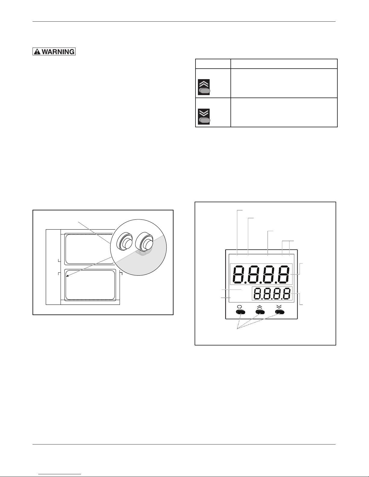
Water Sensors
Figure 5: Location of Water Sensors
NOTE: The controller has an OUT light (red
lamp). This light blinks as the controller
maintains the desired temperature.
Size, weight, pan loading, and product quality will
affectcookingtimesandshouldbeadjustedtot
the requirements of your operation.
Setting Temperature
1. To set temperature:
KEY FUNCTION
Up Key Press and release quickly to increase
the value of the displayed parameter.
Press and hold to accelerate
increment speed.
Down Key Press and release quickly to decrease
the value of the displayed parameter.
Press and hold to accelerate
decrement speed.
2. OUT light will illuminate while cabinet is
warming up.
3. When OUT light is blinking, the cabinet has
reached the desired temperature.
NOTE: Thecontrollerisnotanindicatorofuid
level in the heater or reservoir tank.
Alarm 1 Indicator
Alarm 2 / Output 2 Indicator
Process Value Indicator
Process Unit
Indicator
A1
A2 PV
°C
°F
Set
Point
Value
IndicatorSV
Output 1
OUT
Indicator
Rubber buttons control
setup and set point adjustment.
Upper
Display
Displays
process value,
menu symbol
and error code.
Lower
Display
Displays set
point value,
parameter value
or control
output value.
Figure 6: Control Panel Functions
Preheating
PreheattheThermodynecabinetwhenrstused
for the day or whenever the unit is cold. Preheating
takes approximately 30 minutes at which time the
temperature set point and the actual temperature
will display the same temperature. If the cabinet
has door(s), keep the doors closed during the
preheat cycle.

— 15 —
ELECTRICAL LOCKOUT/TAGOUT
PROCEDURE
: Before performing any
cleaning or maintenance that involves
electrical connection or disconnection
and/or exposure to electrical components,
always follow the Electrical LOCKOUT/
TAGOUT Procedure. Disconnect all circuits.
Failure to comply can cause property
damage, injury or death.
The Electrical LOCKOUT/TAGOUT Procedure is
used to protect personnel working on an electrical
appliance. Before performing any maintenance
or service that requires exposure to electrical
components, follow these steps:
1. In electrical box, place appliance circuit breaker
into OFF position.
2. Place a lock or other device on electrical box
cover to prevent someone from placing circuit
breaker ON.
3. Place a tag on electrical box cover to indicate
that appliance has been disconnected for
service and power should not be restored until
tag is removed by maintenance personnel.
4. Disconnect appliance power cord from
electrical outlet.
5. Place a tag on the cord to indicate that unit
has been disconnected for service and power
should not be restored until tag is removed by
maintenance personnel.
WHEN TO CLEAN
It is recommended that all stainless steel
equipment be cleaned on a regular basis. Any
piece of stainless steel equipment that is soiled
should be cleaned daily to ensure the long life of
the equipment. Routine cleaning will also lessen
stainless steel abrasion.
STAINLESS STEEL CARE
Cleaning
Stainless steel contains 70-80% iron, which will
rust if not properly maintained. It also contains 12-
30% chromium, which forms an invisible passive,
protectivelmthatshieldsagainstcorrosion.Ifthe
lmremainsintact,thestainlesssteelwillremain
intact.However,ifthelmisdamaged,thestainless
steel can break down and rust. To prevent stainless
steel breakdown, follow these steps:
CAUTION: Never use any metal tools.
Scrapers, les, wire brushes or scouring
pads (except for stainless steel scouring
pads) will mar the surface.
CAUTION: Never use steel wool, which will
leave behind particles that rust.
CAUTION: Never use acid-based or chloride-
containing cleaning solutions, which will
break down the protective lm.
CAUTION: Never rub in a circular motion.
CAUTION: Never leave any food products or
salt on the surface. Many foods are acidic.
Salt contains chloride.
For routine cleaning, use warm water, mild soap
or detergent and a sponge or soft cloth.
For heavy-duty cleaning, use warm water, a
degreaser and a plastic, stainless steel or Scotch-
Brite pad.
Always rinse thoroughly. Always rub gently in the
direction of the steel grain.
Preserving & Restoring
Special stainless steel polishing cleaners can
preserveandrestoretheprotectivelm.
Preserve the life of stainless steel with a regular
application of a high quality stainless steel polishing
cleanerasanalsteptodailycleaning.
If signs of breakdown appear, restore the stainless
steel surface. First, thoroughly clean, rinse and
CLEANING AND MAINTENANCE

— 16 —
dry the surface. Then, on a daily basis, apply a
high-quality stainless steel polish according to
manufacturer’s instructions.
Heat Tint
Darkened areas, called heat tint, may appear on
stainless steel exposed to excessive heat, which
causestheprotectivelmtothicken.Itisunsightly
but is not a sign of permanent damage.
To remove heat tint, follow the routine cleaning
procedure. Stubborn heat tint will require heavy-
duty cleaning.
To reduce heat tint, limit the exposure of equipment
to excessive heat.
CLEANING HEAT TRANSFER PLATES
The Thermodyne unit operates on the principle of
conduction, rather than convection. Therefore, it
is very important to keep the heat transfer shelves
clean, so heat transfer may take place with
maximumefciency.Itisalsoveryimportantto
keep the bottom contact surfaces of pots and pans
as clean as possible to ensure even and complete
heattransfer.Thesurfaceandatcoatingofthe
thermal heat transfer shelf is extremely hard, but
will react with strong caustic cleaning solutions
and deteriorate.
CAUTION: Most concentrated soaps and
ammonia cleaners are too caustic to be
used on the Thermodyne unit.
If the coating is destroyed, the heat transfer
shelves will lose their non-stick properties and
their surface hardness.
The cleaners should always be used at the
recommended concentrations. In the case of dry
powders, the powders must not be placed directly
on the surface of the heat transfer plate. Care
must be taken not to scratch the shelf surfaces
when using brushes or pads. If harsh scouring is
needed, use a nylon type scouring pad. NEVER
use steel wool.
It is recommended that a weekly cleaning schedule
be followed to avoid the buildup of heavy food
product deposits. In the event heavy deposits occur
thataredifculttoremovewithordinarycleaning
procedures, stronger chemical cleaning agents
may be applied if the products are intended for food
service use and are also compatible with hard coat
anodized aluminum surfaces. When using these
stronger solvents, it is very important that heat
transfer shelves are rinsed thoroughly with clean
potable water after cleaning. Be sure to remove all
traces of the cleaning agent. Between the regular
scheduled cleaning, wipe off the anodized aluminum
surfaces periodically with a clean damp cloth.
CLEANING DOOR GASKETS
Cleanthegasket-sealing surfaceofthe Thermodyne
doors to remove food product acids for maximum
gasket life. Do not use any solvents or sharp
instruments as these will damage the gasket.
Wash with a cloth moistened in a solution of mild
detergent and warm water. Rinse with a fresh cloth
moistened with warm water to remove all traces of
detergent. Wipe dry with a clean cloth. Never apply
food product oils or petroleum lubricants directly to
the door gasket as these will reduce gasket life.
FLUID REPLENISHMENT
1. Turn the unit off and unplug the unit from the
receptacle.
2. Using a Phillips head screwdriver remove the
four Phillips head screws from the back cover.
3.
Locatethellcaponthetopofthereservoir.
This cap is similar to an automotive radiator cap.
Reservoir
Cap
Reservoir
Figure 7: Reservoir Cap Location

— 17 —
4. Unscrewthereservoirllcap.
5. Using the ll bottle of heat transfer uid
providedwiththeunit,pourtransferuidinto
the reservoir just until the “Add Fluid” light
goesofforwhenthelevelis1″fromthetop.
6. Afterlling,besuretoscrewthellcaprmly
back into place.
7. Replace the back cover and replace the four
Phillips head screws securely.
8. Plug the unit into receptacle and turn red power
switch to the on position.
IMPORTANT:
Adduidonlywhenoveniscold!-Withoven
temperaturebetween34°F.and45°F.
NOTE: Afterlling,besuretoscrewcaprmly
back into place.
NOTE: If the uid indicator light remains on
aftertheunithasbeenlled,contactthe
Thermodyne service department.
CHANGING FLUID
NOTICE: The Thermodyne HeatTransfer Fluid has
lubricating additives, anticorrosion additives, and
heat transfer properties that may decrease with
the passing of time. Thermodyne Heat Transfer
Fluidwillprotecttheunitindenitelyiftheuidis
changed on an annual basis.
CAUTION: The following procedure is to be
performed by a qualied service technician only.
: Before removing any sheet
metal panels or servicing this equipment,
always perform the Electrical LOCKOUT/
TAGOUT Procedure. Be sure all circuits are
disconnected. Failure to comply with this
procedure can cause property damage,
injury or death.
1. Move Power ON/OFF switches to the OFF
position and perform LOCKOUT/TAGOUT
procedures.
2. Drain all water from the hot wells.
Drain
Valve
Figure 8: Drain Valve
3. Allow the unit to cool completely.
4.
Using a Phillips head screwdriver remove the
4 Phillips head screws from the back panel.
5.
Locate the heater tank and remove cap.
Heater Tank
Cap
Heater
Tank
Figure 10: Heater Tank Cap Location
6. Remove the side panel of the side you are
working on to gain access to drain plug.
7. Place a pan or bucket beside drain plug in
ordertocatchdraineduid.

— 18 —
Return
Manifold
Drain
Hose
Drain
Valve
Figure 11: Drain Hose
8. Place drain hose into pan or bucket and turn
valve to open position.
9. Once unit has drained completely turn valve
to off position and tuck drain hose back into
cabinet.
10. Reattach the left side panel.
11.RelltheunitwithThermodyneHeatTransfer
Fluid only. Never substitute with water or other
liquids.
12. Reattach the heater tank cap.
13. Restore power to the unit and place the Power
ON/OFF switch in its ON position.
NOTE:Unitmayrunbrieyandshutoffdueto
lowuidlevel.
14. Remove reservoir cap and heater tank cap
andllheatertank.
Reservoir
Heater
Tank
Figure 12: Fill Heater Tank
16. Repeat steps 12-14 until unit is completely full
ofuid.
17.Once unit is completely lled, reattach the
heater tank cap and the powerhead lid.
NOTE: If ADD FLUID light is on, add uid to
reservoir tank until light goes out.
18. Allow the unit to heat until set temperature is
reached.
19. Once set temperature is reached, place the
power switch in the OFF position and let the
unitcooldowntoatleast100°F.
20. Turn unit back on, and if ADD FLUID light is
onagain,adduidtoreservoirtankuntillight
goes out.
NOTE: Steps 18-20 are very critical in order to
purge any trapped air from the unit.

— 19 —
PROBLEM
No Power:
LOW FLUID light is on –
Oven heating properly:
LOW FLUID light is on –
Hot Well heating properly.
LOW FLUID light is on –
Oven not heating properly:
Heater(s) not working:
Shelves hotter than
set point:
Shelves colder than
set point:
Oven heats up too slow:
POSSIBLE CAUSE
1. Main power switch off.
2. Not plugged in.
3. Breaker off or tripped.
4. Bad contactor.
1.Ovenislowonuid.
1. Hot Well is low on water
1.Ovendisabledduetolowuid
level cut out.
2. Fluid level probe defective.
3. System leak.
1. Unit not properly wired.
2. Bad heater(s).
3. Contactor or solid state relays
not working.
4.Offduetolowuidcutout.
5. Failed temperature controller.
6. High limit snap disc tripped.
1. Temperature controller out of
calibration.
2. Thermocouple defective.
3. Solid state relay(s) stuck on.
4. Failed temperature controller.
1.Lowuidintank.(LOWFLUID
light should be lit)
2. Failed temperature controller.
3. Heater(s) not working.
4. Pump failure.
5. Thermocouple failure.
1. Heater(s) not working.
SOLUTION
1. Turn switch on.
2. Check plug.
3. Check breaker.
4. Replace contactor.
1. Add Thermodyne Heat Transfer
Fluid per instructions.
1. Add water to 3/4" above water
level sensors.
1.Mainheatertankslowonuid.Add
Thermodyne Heat Transfer Fluid
anddeterminecauseofuidloss.
2. Repair or replace.*
3. Repair leak.*
1. Check wiring.*
2. Replace heater(s).*
3. Repair or replace.*
4. Add Thermodyne Heat Transfer
Fluid per instructions.
5. Replace temperature controller.*
6. Reset snap disc and check for
cause.*
1. Recalibrate temperature
controller.*
2. Replace thermocouple.*
3. Replace solid state relay(s).*
4. Replace temperature controller.*
1. Add Thermodyne Heat Transfer
Fluid per instructions.
2. Replace temperature controller.*
3. See “Heater(s) not working”.
4. Repair or replace pump.*
5. Replace thermocouple.*
1. See “Heater(s) not working”.
TROUBLESHOOTING
Mostproblemsassociatedwiththeholdingcabinetareduetolowuidlevel.
Alwayscheckuidlevelrst.
*Recommendedservicetobedonebyaqualiedserviceagency.
NOTE: Most problems associated with the Thermodyne cabinet are due to failure to add Thermodyne
HeatTransferFluid.Checkuidlevelrst.IntheeventserviceisrequiredonyourThermodyne
cabinet, please call: (800) 526-9182.
— 20 —
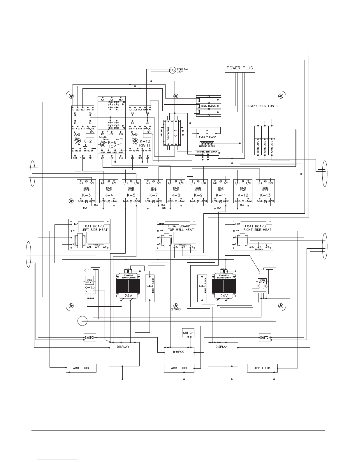
SCHEMATIC WIRING DIAGRAM
2600DP Wiring Diagram
Table of contents
Other THERMODYNE Oven manuals


Popular Oven manuals by other brands


Unold
Unold 68846 Instructions for use

Miele
Miele H6361BP Operating and installation instructions

Zanussi
Zanussi ZBS 703 SS OPERATING AND INSTALLATION Manual

Klarstein
Klarstein 10021587 manual

Omega
Omega OO640X Operating and installation instructions

Campomatic
Campomatic C64EWR Installation and operating instructions