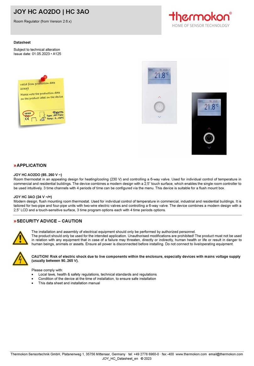
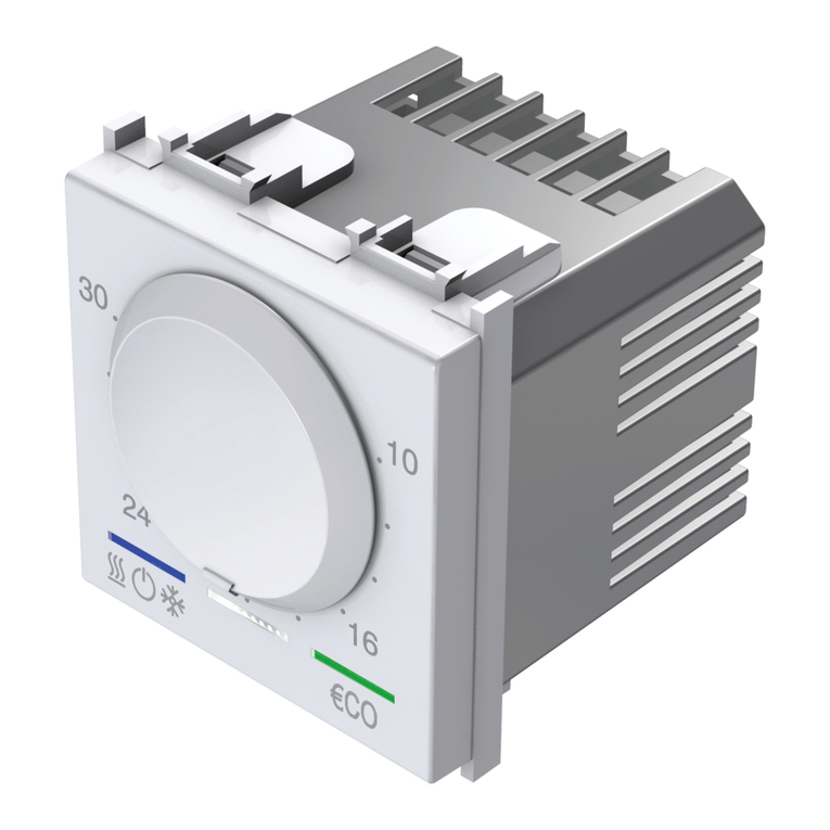
Thermokon JOY Fancoil EC 3AO RS485 Modbus User manual

JOY Fancoil EC 3AO RS485 Modbus
Electronic Fan Coil Thermostat (Flush mounting)
Thermokon Sensortechnik GmbH, Platanenweg 1, 35756 Mittenaar, Germany · tel: +49 2778 6960-0 · fax:-400 · www.thermokon.com · email@thermokon.de
JOY_Fancoil_EC_3AO_Modbus_Datasheet_v1.6.0+_en.docx © 2017
Datasheet
Subject to technical alteration
Issue date: 24.11.2017 • A002
Application
Modern design, flush mounting fan coil room thermostat. Used for individual control of temperature in commercial, industrial and
residential buildings. It is tailored for two-pipe and four-pipe fan coil units with two-wire electric valves or controlling a 6-way valve
(Sauter or Belimo). The device combines a modern design with a 2,5” LCD and a touch-sensitive surface, 3 time program
options each with 4 time periods options.
Security Advice –Caution
The installation and assembly of electrical equipment should only be performed by authorized personnel.
The product should only be used for the intended application. Unauthorised modifications are prohibited! The
product must not be used in relation with any equipment that in case of a failure may threaten, directly or indirectly,
human health or life or result in danger to human beings, animals or assets. Ensure all power is disconnected
before installing. Do not connect to live/operating equipment.
Please comply with
Local laws, health & safety regulations, technical standards and regulations
Condition of the device at the time of installation, to ensure safe installation
This data sheet and installation manual

Page 2 / 8 Issue date: 24.11.2017
Thermokon Sensortechnik GmbH, Platanenweg 1, 35756 Mittenaar, Germany · tel: +49 2778 6960-0 · fax:-400 · www.thermokon.com · email@thermokon.de
JOY_Fancoil_EC_3AO_Modbus_Datasheet_v1.6.0+_en.docx © 2017
Notes on Disposal
As a component of a large-scale fixed installation, Thermokon products are intended to be used permanently as
part of a building or a structure at a pre-defined and dedicated location, hence the Waste Electrical and Electronic
Act (WEEE) is not applicable. However, most of the products may contain valuable materials that should be
recycled and not disposed of as domestic waste. Please note the relevant regulations for local disposal.
Remarks to Room Sensors
Location and Accuracy of Room Sensors
The room sensor should be mounted in a suitable location for measuring accurate room temperature. The accuracy of the
temperature measurement also depends directly on the temperature dynamics of the wall. It is important, that the back plate is
completely flush to the wall so that the circulation of air occurs through the vents in the cover. Otherwise, deviations in
temperature measurement will occur due to uncontrolled air circulation. Also the temperature sensor should not be covered by
furniture or similar devices. Mounting next to doors (due to draught) or windows (due to colder outside wall) should be avoided.
The temperature dynamics of the wall will influence the temperature measurement. Various wall types (brick, concrete, dividing
and hollow brickwork) all have different behaviours with regards to thermal variations.
Surface and Flush Mounting
The temperature dynamics of the wall influence the measurement result of the sensor. Various wall types (brick, concrete,
dividing and hollow brickwork) have different behaviours with regard to thermal variations. A solid concrete wall responds to
thermal fluctuations within a room in a much slower way than a light-weight structure wall. Room temperature sensors installed in
flush boxes have a longer response time to thermal variations. In extreme cases they detect the radiant heat of the wall even if
the air temperature in the room is lower for example. The quicker the dynamics of the wall (temperature acceptance of the wall)
or the longer the selected inquiry interval of the temperature sensor is the smaller the deviations limited in time are.
Technical Data
Measuring values
temperature
Network technology
RS485 Modbus, baud rate 9.600, 19.200, 38.400 or 57.600, parity none (2 stopbits), even or odd (1 stopbit)
Output voltage
3x 0..10 V, EC Fan control, heating & cooling
or control 6-way valves (configurable via Software)
Power supply
24 V = (±10%) or 24 V ~ (±10%) SELV
Power consumption
max. 1,5 W (24 V =)
Measuring range temp.
0..+50 °C
Accuracy temperature
±1 K (typ. at 21 °C)
Inputs
DI 1
1 input for NTC10K or floating contact
DI 3
1 input for floating contact
Control function
setpoint adjustment 0..+50 °C
Display
LCD 2,5“, 240x160 px, white backlighting
Functions
integrated PI-controller
Enclosure
PC, hardened acrylic glass with high scratch resistance
Protection
IP30 according to EN 60529
Connection electrical
Terminal 1..8
terminal block max. 1,5 mm²
Terminal 9..12
terminal block max. 1.0 mm²
Ambient condition
0..+50 °C, max. 85% rH non-condensing
Weight
195 g
Mounting
flush mounted with standard EU box (Ø=55 mm)
Diagnostics Menu
To access the diagnostics menu, select the header in the startscreen of the parameter menu, and press the ENTER key. Here
you will find various information, such as device type, software version, state of the inputs and outputs and controller state
(current manipulated variable).

Issue date: 24.11.2017 Page 3 / 8
Thermokon Sensortechnik GmbH, Platanenweg 1, 35756 Mittenaar, Germany · tel: +49 2778 6960-0 · fax:-400 · www.thermokon.com · email@thermokon.de
JOY_Fancoil_EC_3AO_Modbus_Datasheet_v1.6.0+_en.docx © 2017
Mounting Advices
Plasterboard boxes shall be covered by wall paper or paint to avoid that the plasterboard box's front rim will be partially visible
underneath JOY.
Maybe consider using white plasterboard boxes (i.e. Kaiser 9063-77)
Connection Plan
1 Digital Input 3 7 24 V = (±10%) or 24 V ~ (±10%)
2 EC Fan (0..10 V) 8 -GND
3 Cooling (0..10 V) or 6-way valve 9 Digital Input 1 (or NTC10K)
4 Heating (0..10 V) or 6-way valve 10 GND DI 1
5 GND DI3 11 Modbus A
6 GND 12 Modbus B
Function Description - Buttons
On the touch surface, there are adjustment options for setpoint and fan speed regulation.
With power-button (5), the device can be set in standby mode by pressing the button (if keycard-switch is NOT used). If the
button is used as a occupancy button, the button must be pressed for at least 3s, in all other cases, a short actuation is sufficient.
In standby mode, the display and all outputs are switched off (controller deactivated). The frost and heat protection monitoring
remains active.
Modbus registers can still be read (e.g. room temperature).
The buttons (3) and (4) change
the setpoint in the range ± 3 ° C
(default setting, configurable).
The fan speed can be set by the
Buttons UP (1) and DOWN (2). 3
seconds without any interaction,
the display returns back to main
screen. While pressing of these
buttons, the white LED of the
Power-button (5) lights up for
visual feedback.

Page 4 / 8 Issue date: 24.11.2017
Thermokon Sensortechnik GmbH, Platanenweg 1, 35756 Mittenaar, Germany · tel: +49 2778 6960-0 · fax:-400 · www.thermokon.com · email@thermokon.de
JOY_Fancoil_EC_3AO_Modbus_Datasheet_v1.6.0+_en.docx © 2017
Function Description –Controller/Fan stages
The room thermostat has a "PI controller" for heating and cooling.
6WV (PI-controller 0..10 V)
The usage of a 6-way valve is set via the configuration software. In this case the same manipulated variable is output at
terminals 3 and 4.
The manipulated variable is output as a proportional control signal at the output for the 6-way valve. The type of valve used is set
via the configuration software.
You can choose from 2..10 V / 2..10 V INV (Belimo), 0..10 V DN15 / DN15 INV, DN20 / DN20 INV (Sauter).
Fan stages
In automatic mode the fan speed is linked to the controller. The assignment of the fan stage to the control (heating / cooling, only
heating, only cooling) is freely selectable. To ensure that the fan motor starts reliably, a period of time can be configured in which
the fan starts with maximal value. Using one or more time channels, the fan control have to be set per timechannel and per
period. Via the touch surface the user has the option to override the settings of the device every time. When the next time
channel starts, the fan speed is set to the configured value. The fan is set to automatic mode when the user changes the
occupancy state (occupied↔unoccupied).
EC Fan automatic mode
The 0..10 V (0..100%) control of the fan is proportional to the calculated manipulated variable of the PI controller.
Example:
Calculated manipulated variable 65% → Fan control with 6,5 V.
Calculated manipulated variable 22% → Fan control with 2,2 V.
EC Fan manual
Up to 5 steps (steps) can be set using the configuration software. The set number of steps is divided linearly to the manipulated
variable of 0..100%.
Example:
Max. steps (stages) = 5
Stage 1 = 20%
Stage 2 = 40%
Stage 3 = 60%
Stage 4 = 80%
Stage 5 = 100%
Heating/ cooling with PI-controller (0..10 V)
The time response of the PI control loop depends on the control parameters xp for the proportional area and tn for the reset time
of the integral range. In case of an error variable, the P portion immediately changes the position value proportionally to the error
variable, while the integral portion takes effect after a certain time.
The resulting manipulated variable is output as an analogue 0..10 V signal directly to the outputs.
Proportional range Xp
The proportional band is the deviation in which controller emits 100% value. A small Xp leads to a stronger control action in case
of slight deviations, but increases the oscillation tendency.
Integral time Tn
The reset time Tn is the time which the I-component of the controller would require to produce the same positioning signal that
the P-component forms immediately once the control deviation is present. The effect of the I component decreases with
increasing reset time.
Minimum and maximum actuating variable
This setting defines a fixed minimum or maximum value of the actuating variable. The parameter "Mode selection actuating
variable" can be used to select whether the minimum actuating variable a) is retained until the controller changes its mode or b)
whether the actuating variable of the controller is output to the output only when the minimum actuating variable is exceeded.
Main screen/ Value display
The Display shows the measured value of the internal sensor. The value of an external sensor will be shown if connected and
configured accordingly. The room thermostat controls in this case according to the external sensor.
Max. steps (stages) = 3
Stage 1 = 33%
Stage 2 = 66%
Stage 3 = 100%

Issue date: 24.11.2017 Page 5 / 8
Thermokon Sensortechnik GmbH, Platanenweg 1, 35756 Mittenaar, Germany · tel: +49 2778 6960-0 · fax:-400 · www.thermokon.com · email@thermokon.de
JOY_Fancoil_EC_3AO_Modbus_Datasheet_v1.6.0+_en.docx © 2017
Header Value display
Footer
Header
Current date and time will be displayed in the header. If enabled, ECO-mode status is indicated via symbol .
An attention symbol can be displayed in the header. This symbol has a higher priority than the ECO-mode symbol and is
prefixed instead of this.
Footer
Depending upon the heating or cooling mode, occupancy or window contact status, the corresponding symbols will be shown in
the footer. The symbol “active timechannel” will be shown only if active.
Symbols
Occupancy
Window contact/dew point
Heating/Cooling
Fan Speed
Active timechannel
….
Configuration
The setpoint of the Modbus version can be adjusted to any particular requirements or overwritten by a higher-level control.
Buttons
The configuration menu is activated by simultaneously pressing the buttons “up” (A), “left” (D) and “right” (B) for at least 3
seconds.

Page 6 / 8 Issue date: 24.11.2017
Thermokon Sensortechnik GmbH, Platanenweg 1, 35756 Mittenaar, Germany · tel: +49 2778 6960-0 · fax:-400 · www.thermokon.com · email@thermokon.de
JOY_Fancoil_EC_3AO_Modbus_Datasheet_v1.6.0+_en.docx © 2017
Menu navigation on the touch-surface is performed by pressing the buttons “up” (A), “down” (C), “left” (D), “right” (B) or the power
button. Choose the desired parameter and press “right” (B) to open up the submenu. The menu will default after 30 seconds if no
button is pressed. To exit the menu select the header line and press “left” (D).
Menu → Time channels
Set point and timer can be set in this menu. Three different time channels with four periods of time are available. The Time
channels are prioritised. Channel 3 has the highest priority.
Choose the time channel and press “right” to enter the submenu. It is possible to select the total week as well as individual days
The selected parameter will be marked with the symbol
To edit the parameter of the selected timer, select “Periods” and press “right”.
ECO-mode is also available in the menu “section”, when selecting the dead zone increase from 2 °C to 10 °C. The adjustable
dead zone between the activation of heating or cooling modes enables an optimisation between comfort and energy saving.
The dead zone between heating and cooling in the ECO-mode will be set to the configured deadband range (see common
settings). (default 10.0 K)
Further information for the parameterisation of the time channels, please refer the detailed description of the JOY Modbus. (See
link under software)
Modbus parameter menu
The configuration menu is activated by simultaneously pressing the buttons “up” (A), “down” (C) for at least 5 seconds.

Issue date: 24.11.2017 Page 7 / 8
Thermokon Sensortechnik GmbH, Platanenweg 1, 35756 Mittenaar, Germany · tel: +49 2778 6960-0 · fax:-400 · www.thermokon.com · email@thermokon.de
JOY_Fancoil_EC_3AO_Modbus_Datasheet_v1.6.0+_en.docx © 2017
Inputs
Up to 3 inputs are configurable for functions such as windows contact, dew point, occupancy, change-over or external sensor
option.
Sensor (NTC10K)
The value of an external sensor will be shown if connected and configured accordingly. In this case, the room thermostat
controls according to the external sensor.
Change-Over DI
Which controller is active depends on the state of the Change-Over contact. (Factory default: contact open heating controller
active, contact closed cooling controller active). The terminals 3 and 4 are used as outputs for heating rsp. cooling.
Change-Over Sensor
The Change-Over Sensor is used for switching between heating and cooling mode automatically. If the temperature is below 19
° C, the controller is in cooling mode. If it is above 28 ° C, it is a heating mode.
If an input is configured as a change-over, the room thermostat is automatically in 2-pipe operating mode and both outputs
(terminals 3 and 4) are used as outputs for heating rsp. cooling.
Window contact/Energy hold off
If a window contact is enabled via the digital input, the reference will switch to a setback set point (Heat SP/Cool SP).
Dewpoint
An active dewpoint contact locks the cooling controller.
Occupancy
If occupancy-function is active, the symbol will be displayed automatically. In state of “unoccupied” the heating set point is
reduced by 2K (default setting) rsp. the cooling set point raised by 2K.
Keycard-Switch
When the card is not inserted, the device is switched in sleep mode. Operation of the keys is locked, the display is switched off
and the controller adjusts to the nominal values of the "unoccupied"-State.
Application notice
SD-Card
Micro SD cards can be used to upload a new firmware or a new device configuration. With the PC configuration tool a
configuration file with extended parameter set can be created and uploaded via SD card. Only SD cards formatted in the FAT file
system can be used! NTFS and exFAT file systems are not supported.
Boot Loader
Because of an integrated bootloader a new application (update, upgrade) can be uploaded by means of a SD card. To insert the
SD card, the upper part must be removed. If the boot loader is activated, the ring illumination blinks in a 1s cycle, while display is
not triggered! After recognition of a SD card with a valid application the update process is started. Now, ring illumination blinks in
a 300ms cycle. After a successful update process (Duration approx. 2-3 minutes!) the new application is started
automatically. Afterwards, SD card shall be removed!
Software:
A detailed description of the parameter and the configuration software can be found using the following link.
The parameters for the display, set point, controller and the 6-way valve output configuration can only be
changed via the configuration software.
Address
Adjustable address (1-247)
Baud rate
9600Bd | 19200Bd | 38400Bd | 57600Bd
Parity
Non | odd | even

Page 8 / 8 Issue date: 24.11.2017
Thermokon Sensortechnik GmbH, Platanenweg 1, 35756 Mittenaar, Germany · tel: +49 2778 6960-0 · fax:-400 · www.thermokon.com · email@thermokon.de
JOY_Fancoil_EC_3AO_Modbus_Datasheet_v1.6.0+_en.docx © 2017
Dimensions (mm)
Accessories (optional)
Converter RS485 Modbus - USB Item No. 668293
Table of contents
Other Thermokon Thermostat manuals
