Salus 091FLRF User manual

Programmable Room Thermostat with RF (Volt Free)
Model 091FLRF
User’s Manual


1
GB
INTRODUCTION
This thermostat can replace most common residential thermostats
and is designed to be used with electric, gas or oil heating control
systems.
Unlike ordinary single unit design thermostats, this is a new type of
thermostat separating the operational functions into two units. The
Receiver serves for wiring connections and heat on/off control. The
Control Centre serves as user interface and temperature sensing/
control. The two units are linked by Radio Frequency.
The Receiver is easily installed using the Industry Standard back
plate supplied (for mounting purposes only as no wiring is required
when installing the control centre).
The back plate can be mounted directly to the wall surface.
Installing & Wiring the Receiver
Caution:
Switch off the electric source before installing the receiver.
We recommend that the installation be performed by trained
personnel.
1) This must be 230V AC and fused at 13 amps max.
2) Select a suitable indoor location free from water and moisture.
3) The receiver should not be shielded from the RF signal in any way,
follow ‘Testing the RF Transmission’ section (PAGE 7

2
GB
) of this manual before deciding on a nal location for the receiver
and control centre units.
4) The Receiver should be mounted in a suitable location that is both
accessible for the connection of mains and control wiring, and
allows good reception of the RF signal. The Receiver needs a 230V
AC mains supply to operate, and this should be fused appropriately
(13A max.). The Receiver should be
mounted in a location where it will
not come into contact with water,
moisture or condensation.
The Receiver On/Off switch is
accessible from the front face of the
Receiver, as shown in this picture:
On the front cover of the Receiver you
will see that there is the On/Off switch and two Light Emitting diodes
(LEDs). The switch allows you to turn off the Receiver if necessary
to prevent it calling for heat. The top LED (red) will illuminate when
the switch is in the ‘On’ position and the unit is receiving power. The
bottom LED (green) illuminates when the Receiver unit is receiving
a heat call transmission from the Control Centre.

3
GB
The wiring terminals and RF Address Code
setting DIP switches are located on the rear
of the Receiver, as shown in this picture:

4
GB
Multiple Thermostat Installations
Please note, if using more than one Receiver in the same
installation, be sure that there is at least a 1 metre gap
between receiver units to avoid RF interference.
When installing multiple thermostats you should ensure that you
assign different address codes for each Receiver following the ‘RF
Address Code Setting’ section of this manual. Each Receiver should
be introduced to the installation one at a time with all other receiver
units switched off, also make sure that the batteries are removed
from all other Control Centres.
Install each unit following the ‘TESTING THE RF TRANSMISSION’
section of this manual. Once you are happy with the operation of one
unit you may install the next. Once all Receiver ‘s are installed, if one
unit then seems to function abnormally, try changing the address code
of the control centre & its corresponding receiver again taking care
that the new code given is different to all others in the installation.
The control centre sends RF On/Off signals every 10 min to ensure
the receiver is in the correct state. If for some reason the 1st RF
signal is interrupted you may notice the control centre has started/
stopped calling for heat but the receiver hasn’t switched. Simply wait
10 minutes until the next RF signal is transmitted and the receiver
unit should switch.

5
GB
RF Address Code Setting
If there is another user nearby, e.g. in the next house, your receiver
may be fault triggered by their transmitter. You may select a different
RF address code to prevent this. The receiver can only respond to
RF transmissions with the same address code setting as its own
address code.
1. To adjust address code of Receiver & Control Centre, simply push
up or down on the 5 dip switch levers. The leavers are numbered
1 to 5 from left to right.
Note :
1. Set dip switch on receiver in same ON position as in transmitter.
ON position is marked on each part shown in picture.
Address Code Dip
Switch Leavers.
Factory Defaut Setting Dip switch 1 - 5 in On position.
1 2 3 4 5
ON

6
GB
Factory Defaut Setting Dip switch 1 - 5 in On position.
1 2 3 4 5
ON
Address Code Dip
Switch Leavers.
12345
ON

7
GB
TESTING THE RF TRANSMISSION
It is important to site the Receiver and Control Centre in locations
where the RF signal cannot be interrupted. The receiving range
between Control Centre and Receiver is 60M in open area. Many
factors can affect the RF transmission, shortening the operating
distance e.g. shielding by thick walls, foil back plasterboard, metal
objects such as ling cabinets, general RF interference etc, However,
the range is enough for most household applications.
It is advisable to test the RF transmission from the intended Control
Centre location to the Receiver location before xing the Control
Centre to the wall.
1. Press UP button until the set-point temperature is higher than room
temperature by a few degrees.
2. Wait for a few seconds. The animated fun (heat call indicator) should
appear on the bottom right of the LCD on the control centre.
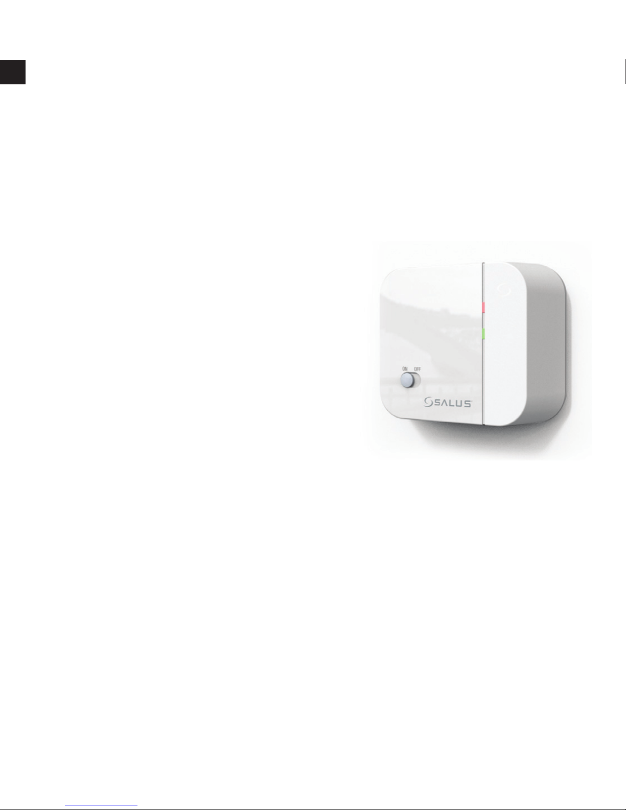
3. Check the green LED on the receiver unit. It should be
illuminated.
4. Press Down button to adjust the set-point temperature to be lower
than room temperature. Wait for a few seconds. The animated ame
(heat call indicator) should disappear and the green LED should
switch off.
5. If at step 3 the LED is not illuminated, press RESET and try to place
the Control Centre closer to the Receiver, repeating steps 1 to 4.
6. Alternatively you can try and alter the address code following the
‘RF Address Code Setting (page 5) of this manual, then repeat
steps 1 to 3.
Note that the RESET button on the Control Centre should be pressed
after altering the add ress code.

8
GB
INSTALLAING THE CONTROL CENTRE
Select a suitable location for the control centre. The location of the
control centre can greatly affect its performance. If it is located where
air circulation cannot reach, or exposed to direct sun light, it will not
adjust the room temperature properly.
To ensure proper operation, the control centre should be installed
at an inside wall with freely circulating air. Find a place where your
family is usually occupied.
Avoid close proximity to heat generating appliances (e.g. TV, heater,
refrigerator) or exposed to direct sunlight. Do not install near a door
where the thermostat will suffer from vibration.
Using the template provided, drill two ø6mm holes in the wall. Insert
the wall anchors and tighten the left screw with 3mm clearance. Fix the
control centre by putting it over the screwhead and slide it rightward
(note the keyhole-like opening at the back of the thermostat). Tighten
the remain screw to lock it in place.
slide it
rightward
Screw now
Note: If the wall is made of wood, there is no need to use the wall
anchors. Drill two ø2.7mm holes instead of ø6mm.

9
GB
USING YOUR NEW CONTROL CENTRE
The following procedures show how to operate the control centre. It
is recommended that you follow the instructions and try to operate
once before connecting it to the heating or cooling system.
1, Start
There is a sliding door on the right half of the thermostat. If you open
the door, you can see some buttons. This door is removable for the
replacement of batteries. After opening the door, you can ip the door
up or down to see the battery compartment.
The control centre is operated by two AA alkaline batteries. Please
remove the front cover and install two new batteries.
When the batteries are installed, the control centre should be
operating and you can see the LCD active. If the control centre does
not work properly, please check the batteries for wrong polarities and
press the reset button by using a ball-point pen.
The LCD after start or reset:
0 6 12 18 24
SUN MON TUE WED THU FRI SAT
PROG

10
GB
Note:
I, Temperature may not be 20°C as the diagram shown and the
Output-On indicator may activate after a few seconds, depending
on different situations.
II, Do not use a pencil to push the reset button. The graphite residue of
a pencil can cause a short circuit and damage the control centre.
LCD
1 Day of the week Indicator
2 Time
3 Temperature
4 Program Number
5 Program Prole Indicator
6 Frost Protection
7 Manual Override Indicator
8 Output-On Indicator – will be displayed and rotates if the ouput is
on. It will disappear if the output is off
9 Low Battery Indicator – will be displayed if the voltage of the
batteries drop to a certain level. Please change the batteries as
soon as possible.
1
2
9
45
7
8
6
3
10
11

11
GB
Temperature mode
You can see
☼
and
on both the buttons and the LCD.
☼
means
comfort temperature and
means economy temperature. These
two temperatures are user changeable. Furthermore, there is a xed
defrost temperature (7°C) indicated by
on the LCD. Throughout the
operation of the thermostat we will refer to them as comfort, economy
or defrost temperature instead of numeric values.
Program
This is a programmable thermostat. It can automatically adjust the
room temperature to a comfortable level when you are at home, and
lower it to save energy when you go out or sleep. What you have to
do is to program the thermostat so that it knows when to raise the
temperature. There are altogether nine programs contained in the
memory of the thermostat. Six of them are preset in the factory and
the remaining three are user changeable.
Manual override
If you want to change the temperature temporarily and do not want
to alter the programs you have set, you can simply touch a button to
override the current program.

12
GB
2, Set day/time
To set day, press d. Similarly, press hto set hour and mto set
minute.
Buttons used:
Example:
When start or after reset, the time is 00:00, Sunday. To set the clock
to current time (e.g., 11:23, Tuesday), press dfor day, hfor hour
and mfor .
Note: When you press and hold the keys for few seconds, the day/
time will change rapidly. Release when the desired setting comes.

13
GB
3, View/Change temperature
Press Temp, and the thermostat enter View/Change temperature
mode. The LCD will show the setting of the current temperature
mode (
☼
,
or
) which will be ashing. Press
☼
or
to review
or change the temperature. Press OK to directly return to normal
operation mode. Buttons used:
Example:
I, In normal mode…
II, Press Temp. The setting
of comfort temperature is
ashing:
III,To change, press
☼
. For
example, to change to 20.0°C,
press
☼
5 times:

14
GB
I V
,To review economy temperature,
press
:
V, You can press
key again to
set the economy temperature,
or press OK to return to normal
operation mode.
Note:
I, The temperature setting range is 5° to 30°C.
II, To lower the setting, enter View/Change temperature mode and
press
☼
or
until it reaches 30°C and then the setting will return
to 5°C. Continue to pressing until the desired setting comes.
III,The setting will change rapidly by pressing and holding the keys.
IV,Please note the temperature mode indicator. A
☼
means the
comfort temperature is being viewed or changed. A
indicates
economy temperature. If is shown, it is defrost temperature. Defrost
temperature is always at 7°C and is not changeable.
V, It is not always necessary to use the OK key to return to normal
operation mode. After couple seconds of no key pressed it will
automatically return to normal mode.

15
GB
4, Manual Override
Press
☼
to select comfort temperature. Press
to select economy
temperature. The current temperature mode will be overrode until
the next set point of the program comes. Press OK to clear override.
Buttons used :
Example:
I, In normal operation mode,
press
to change the current
comfort setting to economy
setting:
The temperature is now set to
economy mode. This mode will
be held until 23:00. (It is because
the program for the day is PROG
1. At 23:00 the temperature
will change from comfort to
economy, which matches the
override setting.)

16
GB
Time hold
Timer hold is an alternative to manual override. Press and hold
☼
(or
) key for few seconds, the hold time will appear. Press the key
again to set the hold time. Press OK to return to normal operation
mode. The maximum can be set is 24 hours. In the hold period the
temperature will not be affected by the program.
When timer hold is active, pressing the corresponding temperature
mode key (e.g.,
☼
if comfort mode is being held) will show the
remaining hold time. The remaining hold time can also be changed
by using the same key. If another temperature mode key is pressed
(e.g., if comfort mode is being held), the timer hold will be cleared.
Example:
I, To change the current setting
from comfort to economy for
5 hours, press and hold
for
few seconds. The hold time will
appear.
II, The hold time is 1 hour. Press
to change the hold time to
5:

17
GB
5, View/Change Programs
Press Prog, the program of the current day is ready to be changed.
Press Prog again to advance to the next day and the program of
that day will be shown.
Press Prog# to change the program.
Program 6, 7 and 8 are user-dene programs. You can use
☼
or
to
change the distribution of comfort or economy temperature and hto
review the setting. Press OK to return to normal operation mode.
Buttons used:
There are altogether nine programs available, as the diagram
shown:
III,Press OK or just leave no key
pressed, the thermostat will
return to normal mode
Note:
I, A ‘hand’ appears when the
current temperature mode is
being overrode.
II, The setting will change rapidly
by pressing and holding the
keys.

18
GB
Example:
I, Assume you want to assign program 6 to Saturday and want to set
the whole day to economy temperature except from 13:00 to 18:00.
Press Prog. The thermostat enters program mode and the program
of the current day (e.g., Tuesday) is ready to be programmed.
The display shows that the program set for Tuesday is program 1,
with the temperature at 00:00 at economy temperature (15ºC).
0 6 12 18 24
PROG 0
0 6 12 18 24
PROG 1
0 6 12 18 24
PROG 2
0 6 12 18 24
PROG 3
0 6 12 18 24
PROG 4
0 6 12 18 24
PROG 5
0 6 12 18 24
PROG 6
0 6 12 18 24
PROG 7
0 6 12 18 24
PROG 8
Program 0 is a special program.
It will set the whole day to defrost
temperature (7°C). (If cooling
mode is selected, it will turn
off the system. See Part 8,
Controlling a cooling system.)
Program 1,2, 3 and 4 are some
typical schedules of a day. You
can select them if you nd them
suitable.
Program 5 sets the whole day
to economy.
Program 6, 7 and 8 are user-
dene programs. They can be
modied to suit your need.
Other manuals for 091FLRF
5
Table of contents
Other Salus Thermostat manuals
Popular Thermostat manuals by other brands

White Rodgers
White Rodgers 1F80-240 Installation and operation instructions

Lennox
Lennox ComfortSense 3000 Series Operation manual

Beok Controls
Beok Controls TGW60 Series manual

Trane
Trane TCONT824 installation guide

Drayton
Drayton Digistat 2 User instructions

Danfoss
Danfoss DEVIreg 610 installation guide

Honeywell
Honeywell RTH2310 operating manual

Honeywell
Honeywell T4398 Series manual

Johnson Controls
Johnson Controls TEC2101-3 N2 installation instructions

Neptronic
Neptronic EVCBM14NIT2S Specification and installation instructions

Thermogroup
Thermogroup 5250 Installation & user guide

Carrier
Carrier TC -PAC installation instructions