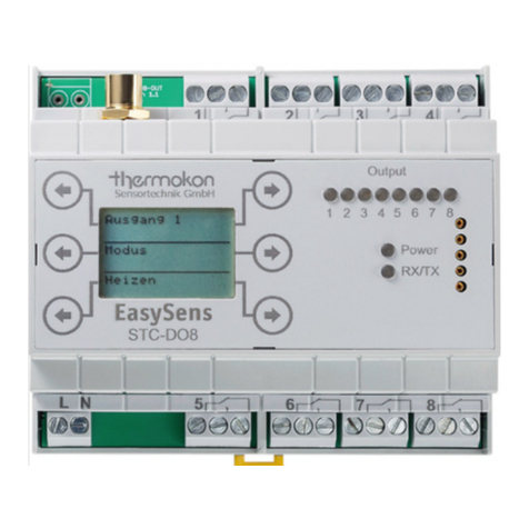
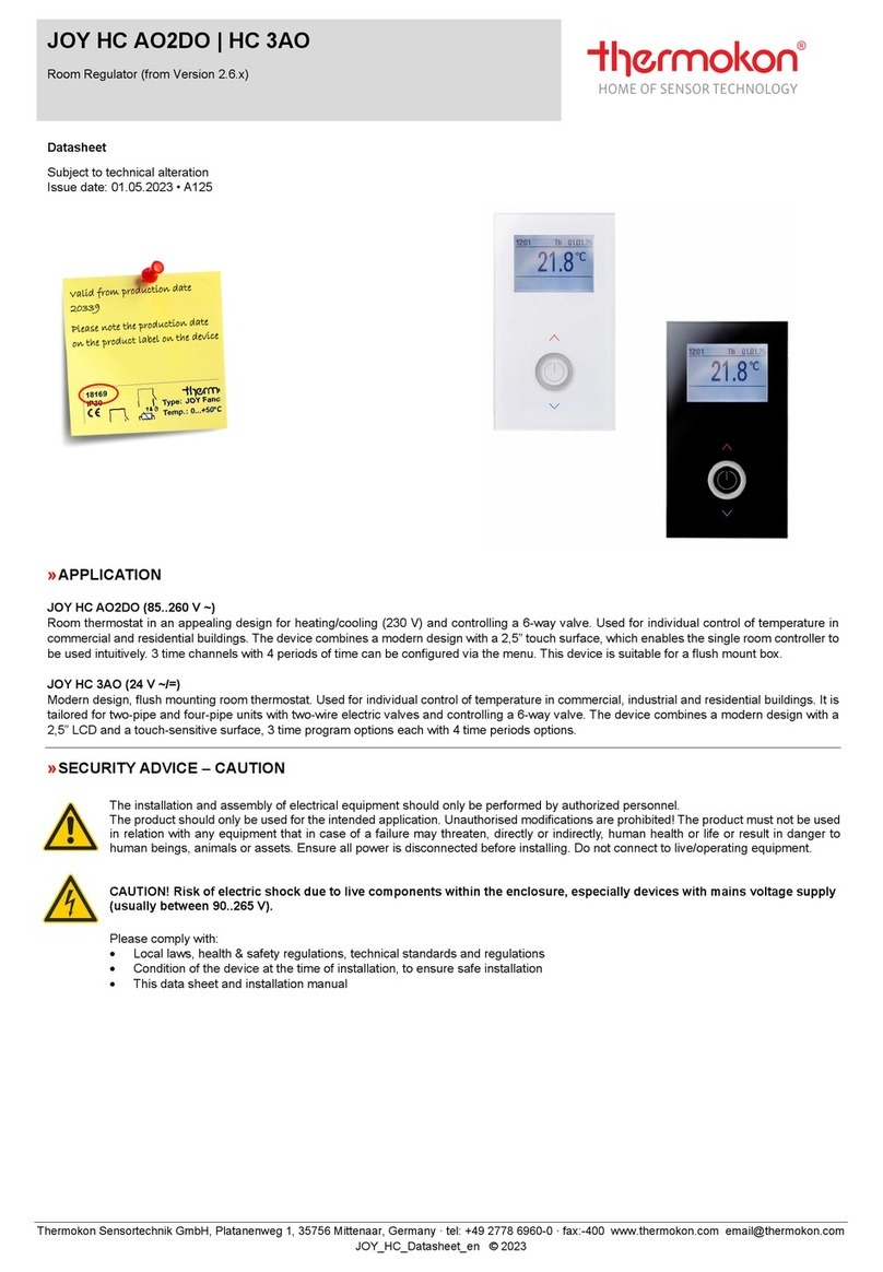
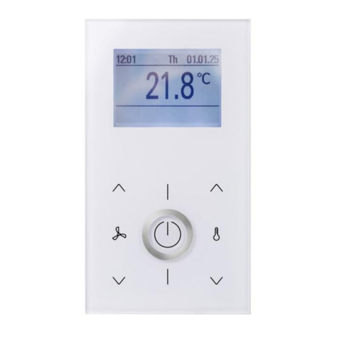
Thermokon NOVOS 7 User manual

Manual NOVOS und thanos EVO
Seite 2Thermokon Sensortechnik GmbH
Revision
Revision
Date
NOVOS 7
NOVOS Touch/
thanos EVO
Description
Author
C
09.06.2020
SW-Ver. 1.0.0
SW-Ver. 1.1.0
• First release
DF
B - D
03.07.2020
• various corrections and additions
DF
E
15.09.2020
SW-Ver. 1.4.0
SW-Ver. 1.3.4
• Scheduler added (Chapter 7.4)
• Auto mode for Shading and Lighting added
DF
SW-Ver. 1.4.0
• Colorpicker added (only NOVOS Touch/ thanos EVO)
• New icons for curtains (shading) added
• Screen lock added
• individual logo for bootscreen, homescreen and
screensaver possible
• Modification register "external sensors 1-4" (register block
508-512 -> r/w /2810-3200 ff.)
• atm. air pressure added
• cyrillic script character added
• additional UI languages: Russian and Czech
• Piezo buzzer (acoustic signal generator, data address
428/429) added
All information without guarantee for correctness and completeness. Subject to change.

Manual NOVOS und thanos EVO
Thermokon Sensortechnik GmbH Seite 3
Table of contents
1General information and safety instructions......................................................................5
1.1 Intended use......................................................................................................................................................................................5
1.2 Improper use .....................................................................................................................................................................................5
1.3 Limitation of liability..........................................................................................................................................................................5
1.4 Support ..............................................................................................................................................................................................5
2Description of product features .........................................................................................6
2.1 Device versions..................................................................................................................................................................................6
3Assembly and commissioning ............................................................................................7
3.1 Connection ........................................................................................................................................................................................7
3.1.1 RS485 Wiring ..........................................................................................................................................................................7
3.1.2 Operation with alternating voltage power supply (AC) .......................................................................................................7
3.1.3 Electrical connection..............................................................................................................................................................7
3.2 RS485 BUS Configuration..................................................................................................................................................................7
3.3 Configuration.....................................................................................................................................................................................8
3.4 Structure of the variables (Data blocks of Modbus-Register).........................................................................................................8
4Display and operation ........................................................................................................8
4.1 Display and operating elements.......................................................................................................................................................8
4.2 Home screen .....................................................................................................................................................................................9
4.2.1 Status bar (Header)................................................................................................................................................................9
4.2.2 Status messages / date and time ....................................................................................................................................... 10
4.2.3 Individual Logo .................................................................................................................................................................... 10
4.2.4 Room temperature and set point ...................................................................................................................................... 11
4.2.5 Favorite buttons.................................................................................................................................................................. 12
4.3 Main menu ..................................................................................................................................................................................... 13
4.3.1 Climate menu (Temperature)............................................................................................................................................. 14
4.3.2 Scene Menu......................................................................................................................................................................... 15
4.3.3 Light menu........................................................................................................................................................................... 15
4.4 RGB(W) Color picker / Color temperature picker......................................................................................................................... 17
4.4.1 Shading menu...................................................................................................................................................................... 18
4.4.2 Monitoring Menu................................................................................................................................................................ 19
4.4.3 Configuration menu ............................................................................................................................................................ 20

Manual NOVOS und thanos EVO
Seite 4Thermokon Sensortechnik GmbH
5RS485 Modbus Register-Specification..............................................................................21
5.1 Data block “Favourites” ................................................................................................................................................................. 21
5.2 Data block “Room Climate” ........................................................................................................................................................... 22
5.3 Data block “Lighting” ..................................................................................................................................................................... 23
5.4 Data block “Shading” ..................................................................................................................................................................... 24
5.5 Data block “Status display and special functions”........................................................................................................................ 25
5.6 Data block “Sensors”...................................................................................................................................................................... 26
6Configuration data blocks ................................................................................................27
6.1 Configuration data block “Device”................................................................................................................................................ 27
6.2 Configuration data block “General” .............................................................................................................................................. 28
6.3 Configuration data block “Display” ............................................................................................................................................... 30
6.4 Configuration data block “Climate” .............................................................................................................................................. 31
6.5 Configuration data block “Lighting” .............................................................................................................................................. 33
6.6 Configuration data block “Shading”.............................................................................................................................................. 37
6.7 Configuration data block “Scenes”................................................................................................................................................ 41
6.8 Configuration data block “Sensors” .............................................................................................................................................. 42
6.9 Configuration data block “Favourites”.......................................................................................................................................... 45
7Coils .................................................................................................................................46
7.1 Coil data block “Lighting”............................................................................................................................................................... 46
7.2 Coil data block “Scenes” ................................................................................................................................................................ 46
7.3 Coil data block “Display” (Icons).................................................................................................................................................... 47
7.4 Coil data block AUTO Mode for “Lighting” 1-8............................................................................................................................. 48
7.5 Coil data block AUTO Mode for “Shading” 1-8............................................................................................................................. 48
7.6 Scheduler - Time channels............................................................................................................................................................. 49
8Unicode character table (UTF-16) ....................................................................................50
9Modbus Protocol .............................................................................................................51
9.1 Supported Control Commands...................................................................................................................................................... 51
9.2 Data Transmission .......................................................................................................................................................................... 51
9.2.1 Master/Slave Protocol ........................................................................................................................................................ 51
9.2.2 Data Frame .......................................................................................................................................................................... 51
9.2.3 Transmission Mode RTU..................................................................................................................................................... 52

Manual NOVOS und thanos EVO
Thermokon Sensortechnik GmbH Seite 5
1General information and safety instructions
The prerequisite for a safe working environment is the compliance with the forth-following specified safety instructions and handling instructions. Only
an authorized electrician may conduct the installation and assembly of electrical devices. Due to their professional training, knowledge and experience
as well as their knowledge of relevant national standards and regulations, a qualified electrician is able to conduct work on electrical systems and figure
out possible threats immediately. The qualified electrician has to have an expertise for the working environment in which he/she works in and knows
the relevant standards and regulations.
Please read the operating instructions carefully before commissioning the device.
The device may only be used for the purposes and applications described in this operating manual.
No technical changes or unauthorized modifications may be conducted to/on the device.
The device may not be used if the ambient conditions (temperature, humidity etc.) are not within the limits given in the specification.
The device should only be cleaned with a damp cloth. Do not use aggressive or solvent-based cleaning liquids. Failure to observe the safety
instructions may result in damage to the device and harm to the user.
Detailed information can be found in the document Care_instructions_for_room_operating_units_en.pdf.
→ Link PDF - Care instructions for room operating units
A faulty connection can lead to destruction of the device
1.1 Intended use
The device is intended for use in an RS485 network.
The room control unit is intended for use in offices, meeting or conference rooms, hotels, reception/lobby areas, nursing homes and hospitals, and
generally in commercial and residential buildings. The room control unit is used for local room control for lighting, blinds, scenes and HVAC
applications.
The device may only
be used and operated in a proper environment
be operated according to the corresponding specifications.
1.2 Improper use
The room operating units must not be used for or be part of medical devices, which maintain, control or otherwise impact human life or physical
health.
The device must not be used in hazardous areas.
The device must not be used in an atmosphere in which a chemically active substance is present.
1.3 Limitation of liability
All information and notes in this manual have been compiled in accordance with the applicable standards and regulations, the state of the art and our
extensive knowledge and experience.
The manufacturer accepts no liability for damage due to
Non-compliance with these instructions
Unintended/improper use
Installations conducted by non-professional persons
Arbitrary conversions or technical modifications
The actual scope of delivery may deviate from the explanations and illustrations described here in the case of special designs, additional product options
or latest technical changes.
1.4 Support
Our support team is available for technical information.
Information about the responsible contact person can be obtained at any time by telephone or e-mail. You may also visit our website for contact
details:
See https://www.thermokon.de/en/contact/contact-persons/
We appreciate your contributions, feedback and user experiences in order to constantly improve our products!

Manual NOVOS und thanos EVO
Seite 6Thermokon Sensortechnik GmbH
2Description of product features
The Thermokon room control units (NOVOS family and thanos EVO) combine all relevant room functionalities for an intelligent room control in one
device, such as temperature control or control of fans, luminaires, blinds or screens. Additionally, depending on the device configuration, up to four
sensors can be integrated (CO2, VOC, temperature, humidity) to maintain a comfortable room climate throughout.
The room control units offer the following main features:
Integration of up to four different sensors (temperature, relative humidity, CO2 and VOC)
Intuitive and comfortable control of room climate
Call up ECO mode for energy-savings and a sustainable climate control ("Green Leaf")
Control of fan coils and other ventilation devices
Control of lighting fixtures and shades
Call up individually defined scenes (e.g.: meeting, presentation, break, not occupied)
Display of text messages, further information and operating states, such as "Window open", room occupied/unoccupied etc.
Structured visual presentation of measured values with trends and traffic light indication
Digital input for external devices (e.g. window contacts, dew point sensor etc.)
2.1 Device versions
NOVOS 7
NOVOS Touch
thanos EVO
NOVOS Touch and thanos EVO are functionally identical and only differ in design.

Manual NOVOS und thanos EVO
Thermokon Sensortechnik GmbH Seite 7
3Assembly and commissioning
Proper commissioning ensures a seamless and safe use of the devices. Please observe the instructions in the corresponding data sheet.
3.1 Connection
3.1.1 RS485 Wiring
The maximum cable length per line should not exceed 1,200 meters. The last device in a line must be terminated with a 120 Ohm resistor to avoid
signal reflections from the BUS. Please make sure, that both resistors are properly connected to the terminals. The MODBUS specification requires
the use of terminating resistors (120 - 150 Ohm, 0.25 W) at both ends. The terminating resistor is not included in the delivery of the devices.
The room operating units load the BUS with a standard BUS load (1/1 unit load according to the RS485 standard). This allows up to 32 room operating
units to be operated on one single BUS line.
Please also note that RS485 does NOT support star topologies and no stub line connection!
If no signals are present on the BUS, it must be ensured that the signal levels (voltage) are fixed. This can be done through pull-up / pull-down
resistors on the drivers. These form a voltage divider with the installed BUS termination resistors. It must be ensured, that there is at least a
differential voltage of 200mV detectable for the receiver between the data lines A and B.
3.1.2 Operation with alternating voltage power supply (AC)
If several field devices are supplied from one AC voltage source according to the specification, it is mandatory, that all "positive" operating voltage
inputs (+) of the field devices are connected to each other, and all "negative" operating voltage inputs (-) = reference potential are connected to
each other (series connection of the field devices).
If the polarity of the supply voltage is reversed on one of the field devices, a short circuit of the supply voltage would occur. The short-circuit current
thus flowing through this field device leads to a damage of this device.
Pay attention to a correct wiring!
3.1.3 Electrical connection
Connect the power supply and the RS485 lines according to the wiring diagram. Power must be supplied from sources that meet the requirements
for protective low voltage. After switching on the power supply, the device starts up.
3.2 RS485 BUS Configuration
Each device that communicates through Modbus is assigned a unique address. In serial networks, only the node assigned as the Master may execute a
command. The BUS interface can be parameterized by means of the NOVOSapp or using the onboard screen configuration menu.
NOVOS 7
NOVOS Touch / thanos EVO
Bus address
1-247 (Address 1 – factory default)
1/1 Bus load per device,
corresponds to 32 participants per segment
Baud rate
9600
19200
38400
57600
76800
115200
(factory default)
4800
9600
14400
19200
38400
56000
57600
76800
115200
(factory default)
Parity and stop bit
Even
Odd
None, 1 Stop bit
None, 2 Stop bits
(factory default)
|
__
DI
Digital Input (für potentialfreien Kontakt → GND)
|
__B- ____________ BUS B
|
__B- ____________ BUS B
|
__A+____________ BUS A
|
__A+____________ BUS A
|
__GND_________ 0 V⏊
|
__UB+__________ 24 V ⎓(±10%) / 24 V ∿(±10%) SELV

Manual NOVOS und thanos EVO
Seite 8Thermokon Sensortechnik GmbH
3.3 Configuration
The first section of this document provides a basic overview of the functions and parameterization options of the device. For configuration, the software
NOVOSapp (for mobile devices) or as a plug-in for our configuration interface uConfig (for PC/Laptops) is available.
The following options are available to configure the device:
Parameterization with mobile end devices via Bluetooth and NOVOSapp. A Bluetooth dongle (accessory) is required.
Bluetooth dongle item no.: 668262
The NOVOSapp for Android or Apple mobile devices is available at the Google Play Store or Apple AppStore
Parameterization via desktop PC/laptop with the uConfig software (option 1) and a USB/RS485 converter (item no.: 668293)
Parameterization via desktop PC/laptop with the uConfig software (option 2), and a micro USB/RS232 converter (item no.: 597838)
Parameterization via building management System (BMS) using the RS485 Modbus network
3.4 Structure of the variables (Data blocks of Modbus-Register)
The parameters are split into two main groups: the configuration parameters and the communication data. The configuration parameters are e.g.
device information or operating parameters that determine how the device processes the sent/received data. The configuration parameters are
permanently stored in a non-volatile memory (EEPROM) (exception: date and time). The communication data are variable data, which the Master and
Slave exchange with each other. These data are not stored in the EEPROM.
4Display and operation
4.1 Display and operating elements
The NOVOS 7 has an intuitive user interface using a rotary/press encoder and four capacitive keys below the screen. NOVOS Touch and thanos EVO
have a high-resolution full-touch display, which is used for operating and navigating through the menus. Both devices use a structured and language-
neutral graphical user interface.
NOVOS 7
NOVOS Touch
thanos EVO
3,5“ TFT
4,8“ TFT
320x480 Pixel
1120x480 Pixel
4 capacitive keys
rotary/press encoder
Full touch

Manual NOVOS und thanos EVO
Thermokon Sensortechnik GmbH Seite 9
4.2 Home screen
The display on the home screen of the NOVOS room control units can be parameterized. All icons and notifications
can be de-/activated individually. The set point and actual value can also be overwritten. In order to preserve the
display illumination, it is recommended to either dim or completely switch off the display brightness in standby
mode. To reduce the risk of ablation effects of the screen content, it is recommended to use the screen saver. By
default, the screen saver switches on 120 seconds after the last user interaction. If the room control unit must be
protected against unauthorised use, a screen lock can be set up with an unlock code of 4 digits. The screen lock
becomes active when the room control unit switches to standby mode.
4.2.1 Status bar (Header)
In the header of the main screen, various icons can be shown or hidden as needed through a software variable or
user interaction (e.g. occupancy). Communication icons are only linked to an internal logic.
NOVOS 7 NOVOS Touch / thanos EVO
Condensation (Icon ON/OFF)
Window open (Icon EIN/AUS)
Calibration due (Icon EIN/AUS with logic)
In connection with the calibration countdown, the
icon is automatically displayed after the time until
next calibration has expired. The calibration
countdown must be set so that the icon appears
after specified time. After the countdown has
elapsed and calibration is completed, the
countdown must be reset and the icon switched
off.
BUS communication error (logic)
If no valid BUS communication is detected within
30 seconds, the icon will automatically appear.
USB communication mode (logic)
When the USB connection via the MicroUSB port
on the bottom of the device is active, the icon
automatically appears.
Room occupancy - occupied/unoccupied
Description see “ECO function”.
ECO function
(Icon ON/OFF or user interaction)
The room occupancy and ECO function are
triggered on the device via toggle button.
NOVOS 7: Depending on the configuration,
switching to ECO mode is conducted either in the
respective submenu (carousel), in the
temperature menu or through a favorite button.
NOVOS Touch/thanos EVO: Select ECO in the
temperature menu or - if configured - also via a
favorite key.
Heating mode(Icon ON/OFF)
The icons “heating” and “cooling” can also be
displayed in color (heating = red / cooling = blue).
For this purpose, the corresponding parameter
must be set in the display settings. The set point in
the center of the home screen is then displayed in
the same color as the setting.
Cooling mode (Icon ON/OFF)
For additional settings, see "Heating mode".
PIR active (Icon ON/OFF)
Warning (Icon ON/OFF)
Maintenance due
In connection with the maintenance countdown,
the icon is automatically displayed after the
maintenance countdown has elapsed. In order to
have the icon appear, the maintenance interval
must be set. After the countdown has expired and
maintenance has been conducted, the countdown
must be reset and the icon should be switched off
again.
Coil data block „Display“ (Icons)
▪ Condensation
▫Coil 16
On = 1 | Off = 0
▪ Window open
▫Coil 17
On = 1 | Off = 0
▪ Calibration due
▫Coil 18
On = 1 | Off = 0
▪ Communiaction error
▪ USB Communication mode active
▪ Heating mode
▫Coil 22
On = 1 | Off = 0
▪ Cooling mode
▫Coil 23
On = 1 | Off = 0
▪ PIR
▫Coil 24
On = 1 | Off = 0
▪ Warning
▫ Coil 26
On = 1 | Off = 0
▪ Maintenance due
▫ Coil 27
On = 1 | Off = 0
Data block „Room climate“
▪ Room occupancy
▫ Data address 100
unoccupied = 0 | occupied = 1
▪ ECO function
▫ Data address 101
ECO not active = 0 | ECO active = 1
Configuration data block „Display“
Display icons and heating/cooling set point
in color (red/blue)
▫ Data address 1212
On = 1 | Off = 0
Configuration data block „General“
▪Kalibrierungscountdown; Adresse 1114
▪Kalibrierungsintervall: Adresse 1116
▪Wartungscountdown; Adresse 1113
▪Wartungsintervall; Adresse 1115

Manual NOVOS und thanos EVO
Seite 10 Thermokon Sensortechnik GmbH
4.2.2 Status messages / date and time
NOVOS 7 NOVOS Touch / thanos EVO
4.2.3 Individual Logo
With the NOVOS app or uConfig, an individual graphic can be loaded into the room control unit.
This graphic can be used as a logo for the boot screen, instead of the time and date on the home
screen or as a screensaver.
NOVOS 7 NOVOS Touch / thanos EVO
During operation, any text messages (max. 24
characters), room names, status messages and other
notifications e.g. alarms can be displayed in the main
screen. Unicode (see chapter 8) is used to display
characters, letters and numbers. A data address is
available for each character. The status messages
are not stored and must be written again by the BMS
after each restart of the device. Characters are
written from left to right.
Example text: TEST
Address 400 = 54 (HEX): T
Address 401 = 45 (HEX): E
Address 402 = 53 (HEX): S
Address 403 = 54 (HEX): T
Time and Date
Time and date can be shown or hidden independently
of each other. The date formats DD.MM.YYYY or
MM.DD.YYYY and the time formats 24h or 12h
(AM/PM) are available. The date and time displays are
active on delivery and are shown in the format 24h -
DD.MM.YYY.
NOVOS 7
resolution: 320x210 px
colour depth 32-bit
picture format: bmp
NOVOS Touch/ thanos EVO
resolution: 480x210 px
colour depth 32-bit
picture format: bmp
Data block „status display“
▪Statusmeldung
▫Datenadresse 400-423
Configuration data block „general“
▪Format Date
▫Data address 1104
0 = Display Off
1 = DD.MM.YYYY
2 = MM.DD.YYYY
▪Format time
▫Data address 1105
0 = Display Off
1 = 12h (AM/PM)
2 = 24h
▪Setting Date
▫Year; Data address 1106
▫Month; Data address 1107
▫Day; Data address 1108
▪Setting time
▫Hour; Data address 1109
▫Minute; Data address 1110
▫Second; Data address 1111
Configuration data block „Display“
▪Screensaver
▫Data address 1207
0 = Off
1 = Date/ Time
2 = individual graphic
▪Display of an own logo (binary coded)
▫Data address 1213
bit 0 = 1, Display graphic on bootscreen
bit 1 = 1, Display graphic on homescreen

Manual NOVOS und thanos EVO
Thermokon Sensortechnik GmbH Seite 11
4.2.4 Room temperature and set point
NOVOS 7 NOVOS Touch / thanos EVO
Room temperature and set point can be shown or
hidden independently. In addition, the set point can
displayed as an absolute or relative value. The room
temperature and set point can be overwritten by the
BMS at any time during operation.
As a default configuration, the display shows room
temperature and set point and the set point is
displayed as an absolute value. The adjustment
range of the set point is ± 3K on delivery and the
step width of the adjustment is ±0.5K. All the above
settings can certainly be configured as required.
In conjunction with the heating and cooling icons in
the header, the set point can also be displayed in
color (heating set point = red / cooling set point =
blue).
Data block „Climate“
▪Set point
▫Data address 103
▪Room temperature
▫Data address 106
Configuration data block „Climate“
▪Selection – which values are displayed on
the home screen
▫Data address 1313
1 = Display room temperature
2 = Display set point
3 = Display both values
▪Set point definition
▫ Data address 1301
0 = absolute | 1 = relative
▪ Base set point
▫ Data address 1302
210 = 21,0 °C
▪ Set point adjustment range
▫ Data address 1303
30 = ±3,0K
▪Set point adjustment step width
▫ Data address 1304
1-50 = ±0,1K - ±5,0K

Manual NOVOS und thanos EVO
Seite 12 Thermokon Sensortechnik GmbH
4.2.5 Favorite buttons
The favorite buttons can be assigned with freely selectable functions. The names of the individual lights or scenes
can be defined individually. In addition to the up to eight lightings/lighting groups or scenes, functions such as
Presence (Presence/Absent), ECO (ON/OFF) and the Climate, Lighting, Blind, Scenes and Monitoring menus can be
assigned as favorite buttons (see Specification tab; "General" configuration data block).
NOVOS 7
NOVOS Touch / thanos EVO
Favorite buttons NOVOS 7
Below the screen there are four configurable
capacitive touch buttons. The corresponding
symbols are displayed in the footer of the main
screen. These keys correspond to the parameters of
the favorite buttons 2 to 5. The push function of the
rotary/push encoder corresponds to the favorite
button 1. If the favorite button 1 is pressed in
standby or on the home screen, the respective
function is triggered and the corresponding symbol
is displayed on the home screen for approx. 3
seconds.
Favorite buttons NOVOS Touch / thanos EVO
If only one favorite button in the home screen is
required, address 1117 (button 1) must be written. If
several favorite buttons are needed (two to a
maximum of four), the data addresses 1118 to 1121
(keys 2 to 5) must be assigned the desired favorite
functions as well.
Configuration data block „General“
▪Favorite button 1
▫ Data address 1117
▪Favorite button 2
▫ Data address 1118
▪Favorite button 3
▫ Data address 1119
▪Favorite button 4
▫ Data address 1120
▪Favorite button 5
▫ Data address 1121
0 = no function
1 = Light 1
2 = Light 2
3 = Light 3
4 = Light 4
5 = Light 5
6 = Light 6
7 = Light 7
8 = Light 8
9 = Scene 1
10 = Scene 2
11 = Scene 3
12 = Scene 4
13 = Scene 5
14 = Scene 6
15 = Scene 7
16 = Scene 8
17 = Occupancy
18 = Eco
19 = Menu Climate
20 = Menu Light
21 = Menu Blind
22 = Menu Scenes
23 = Menu Monitoring
24 = Menu Fan control (NOVOS 7)
Favorite button 2-5
Favorite button 1
Favorite button 2-5
Favorite button 1

Manual NOVOS und thanos EVO
Thermokon Sensortechnik GmbH Seite 13
4.3 Main menu
NOVOS 7
NOVOS Touch / thanos EVO
NOVOS 7 Carousel
(main menu)
By turning the encoder, the NOVOS 7 switches to the
main menu (carousel). The menu is still operated by
the rotary/press encoder. All functions i.e. symbols
(except the settings menu) can be activated or
deactivated individually. All menu items are active
during initial installation.
NOVOS Touch / thanos EVO Menu bar
(Navigation
bar)
The menu bar is located at the bottom of the touch
display (equivalent to the carousel of the NOVOS 7).
The menu bar is a central element on the home
screen. With a swipe gesture, you can switch
between the menu pages in the menu bar. In the
menu bar, all menu items are displayed as buttons.
The activation of the ECO mode, switching of room
occupancy and the submenu for fan speed
adjustment are arranged in the Climate menu -
unlike the NOVOS 7. To activate or deactivate the
ECO mode and to trigger the room occupancy status,
simply touch the button.
Configuration data block „General“
▪ Display menu monitoring
▫ Data address 1122
0 = no
1 = yes
Configuration data block „Display“
▪ Display button standby
▫ Data address 1205
0 = no
1 = yes
Configuration data block „Climate“
▪ Display menu temperature
▫ Data address 1300
0 = no
1 = yes
▪ Display button ECO
▫ Data address 1305
0 = no
1 = yes
▪ Display room occupancy
▫ Data address 1306
0 = no
1 = yes
▪ Display fan control
▫ Data address 1308
0 = no
1 = yes
Configuration data block“Lighting“
▪ Display menu light
▫ Data address 1400
0 = no
1 = yes
Configuration data block „Shading“
▪ Display menu shading
▫ Data address 1600
0 = no
1 = yes
Configuration data block „Szenen“
▪ Display menu scenes
▫ Data address 1800
0 = no
1 = yes

Manual NOVOS und thanos EVO
Seite 14 Thermokon Sensortechnik GmbH
4.3.1 Climate menu (Temperature)
The climate control menu contains the set point, fan stage adjustment, ECO function and presence. The set point
(shift) can be display with relative or absolute values. With the ECO mode being active, it is not possible for the user
to adjust the set point and fan stages.
NOVOS 7
NOVOS Touch/thanos EVO
NOVOS 7 climate menu
The operation of the menu is intuitively lead by using
the rotary/push button. The buttons for ECO, room
occupancy and fan speed adjustment can be
optionally displayed in the Temperature menu. On
delivery, these buttons are not active in the Climate
menu, the set point is shown as an absolute value of
21°C and the set point adjustment is uses a stepwidth
of 0.5K in the range of ±3K around the base set point
(21°C). This can be customized individually. If the fan
stage is activated in the climate menu, the adjustment
can be performed directly using the button, toggling
through the fan stages (see below).
Example with factory settings
► ► ►►
ECO mode
„not active“
►
„active“
Room occupancy
„unoccupied“
►
„occupied“
NOVOS Touch / thanos EVO Climate Menü
The buttons for fan stage adjustment, ECO mode and
room occupancy are an integral part of the air-
conditioning (AC) menu. ECO mode and room
assignment are activated or deactivated directly
through the toggle button. When the button for the
fan function is pressed, the menu for fan stage
adjustment is called up. The fan stage can be selected
with a swipe gesture (up/ down). If the ECO mode is
active, neither the set point nor the fan stage can be
changed. Despite the option that a user can change
the ECO model, the ECO mode can also be
overwritten from the BMS.
Configuration data block „Climate“
▪Set point definition
▫ Data address 1301
0 = absolute | 1 = relative
▪ Base set point
▫ Data address 1302
210 = 21,0 °C
▪ Set point adjustment range
▫ Data address 1303
30 = ±3,0K
▪Set point adjustment step width
▫ Data address 1304
1-50 = ±0,1K - ±5,0K
▪Display ECO button
▫ Data address 1305
0 = no | 1 = Menu bar or Carousel
for NOVOS 7:
2 = Carousel and climate menu
▪Display room occupancy button
▫ Data address 1306
0 = no
1 = Menu bar or Carousel
for NOVOS 7:
2 = Carousel and climate menu
▪Room occupancy after restart
▫ Data address 1306
0 = unoccupied
1 = occupied
▪Display fan control
▫ Data address 1308
0 = no
1 = Menu bar or Carousel
for NOVOS 7:
2 = Carousel and climate menu
▪Number of stages
▫ Data address 1309
0-5
▪Fan stage AUTO available
▫ Data address 1310
0 = no
1 = yes
▪Minimum fan stage
▫ Data address 1311
0-5
▪Fan stage after Reset
▫ Data address 1313
0-5 = Fan Off– Stage 5
6 = Auto

Manual NOVOS und thanos EVO
Thermokon Sensortechnik GmbH Seite 15
4.3.2 Scene Menu
In the Scene menu, up to eight scenes can be configured individually. Scenes can be activated or deactivated using
the rotary/push button (NOVOS 7) or the touch display (NOVOS Touch).
NOVOS 7 NOVOS Touch/thanos EVO
4.3.3 Light menu
In the Light menu, it is possible to manage up to eight lighting groups. Depending on the technical conditions, the
individual light groups can be switched or dimmed individually.
NOVOS 7
Scene groups
Buttons for up to eight different scenes can be
created for a quick change of the room status and
peripheral devices connected. The names of the
individual scenes (max. 12 characters) can be freely
assigned. Nine different scene icons can be selected
for customization.
There is no linkage between the individual scenes. If
scenes are mutually exclusive, this logic must be
performed by the BMS.
Lighting groups NOVOS 7
There are four different icons and a maximum of 12
characters available for the name.
If a light is dimmable, this is indicated in the button
with the dimming symbol. If the dimming
adjustment is parameterised with a "slider", the
percentage of dimming is also displayed. The
dimming value can be set by the user with the
rotary/push button in the respective sub-menu of
the lighting group. If dimming is configured as “push
button” mode instead of the “slider” bar, the
percentage value does not get displayed and the
dimming adjustment is performed with 2 push
button commands (+) and (-).
Non-dimmable lights are switched ON or OFF
directly with the push-button. In this case, a short or
long push-button action is shown in the respective
register. After the register has been read, it will
automatically be reset to “NoPress”.
Example
Light 1
„not active“
►
„active“
Configuration data block „Scenes“
▪Number of scenes
▫ Data address 1801
0-8
▪Selection the icon for scenes
▫ Icon scene 1; Data address 1415
▫ Icon scene 2, Data address 1433
▫ Icon scene 3; Data address 1451
▫ Icon scene 4; Data address 1469
▫ Icon scene 5; Data address 1487
▫ Icon scene 6; Data address 1505
▫ Icon scene 7; Data address 1523
▫ Icon scene 8; Data address 1541
0 = Work
2 = Cinema
4 = Sleep
6 = do not disturb
8 = Scene
Configuration data block „Light“
▪Number of lighting groups
▫ Data address 1401
0-8
▪Selection of the lighting icons
▫ Light 1; Data address 1415
▫ Light 2, Data address 1433
▫ Light 3; Data address 1451
▫ Light 4; Data address 1469
▫ Light 5; Data address 1487
▫ Light 6; Data address 1505
▫ Light 7; Data address 1523
▫ Light 8; Data address 1541
0 = Universal bulb
1 = Spot
2 = Light cassette
3 = Floor lamp
1 = Präsentation
3 = Party
5 = Dinner
7 = Cleaning

Manual NOVOS und thanos EVO
Seite 16 Thermokon Sensortechnik GmbH
NOVOS Touch/thanos EVO
NOVOS Touch/thanos EVO
Configuration data block „Light“
▪Display of the lighting groups
▫ Data address 1402
List view = 0
Floor plan = 1
Display both = 2
Lighting groups NOVOS Touch / thanos EVO
Equivalent to NOVOS 7, up to eight different lighting
groups can be controlled with NOVOS Touch and
thanos EVO. Four different icons and max. 12
characters for the name are available.
If a light is dimmable, this is indicated by the
dimming symbol inside the button of the respective
light group. If the dimming adjustment is
parameterised as a "slider", the percentage of
dimming is also displayed. The dimming value can be
set by the user with a "Swipe" gesture in the
respective sub-menu of the lighting group.
By clicking the button, the luminaire or lighting
group can be switched ON and OFF again directly.
The last dimming value is assumed.
If dimming is configured as “push button” mode
instead of the “slider” bar, the percentage value
does not get displayed and the dimming adjustment
is performed with 2 push button commands (+) and
(-). In that case, a short or long key press is shown in
the respective register. After the register has been
read, it will automatically be reset to “NoPress”.
Non-dimmable lights are switched on or off directly
with the button.
2D room/floor plan display
As an alternative or in addition to the list
visualization, a room can be graphically visualized in
two dimensions with NOVOS Touch or thanos EVO.
The luminaires are displayed in the plan by lighting
symbols. An exact positioning of the buttons is
possible through a coordinate system. For example,
a floor plan (1-bit color depth, black/white) of a
room can be uploaded into the device. The upload
can be conducted using the “uConfig” software. It
must be ensured that the image size is 960x800
pixels. If a lighting group is dimmable, the respective
button in the room plan must be pressed for longer
than two seconds to access the dimming menu.
User key lock
(AUTO mode, Data address 208 | Coil 32-39)
With NOVOS 7, Touch and Thanos EVO, the keys of
the individual lighting circuits can be blocked by the
BMS. All locked keys of the respective lighting group
are greyed out in the entire user interface and
cannot be operated by the user. In active Auto
mode, the locked lighting groups are switched and
dimmed exclusively by the BMS via Modbus.

Manual NOVOS und thanos EVO
Thermokon Sensortechnik GmbH Seite 17
4.4 RGB(W) Color picker / Color temperature picker
Konfigurationsdatenblock „Licht“
▪Lichtgruppe Verstellung
▫ Light 1; Data address 1416
▫ Light 2; Data address 1434
▫ Light 3; Data address 1452
▫ Light 4; Data address 1470
▫ Light 5; Data address 1488
▫ Light 6; Data address 1506
▫ Light 7; Data address 1424
▫ Light 8; Data address 1542
Slider = 0
Push button operation = 1
Push button operation (raw) = 2
RYB Color picker = 3
(color circle + dimmer slider)
Color temperature picker = 4
(color circle + dimmer slider)
▪Limit values color temperature
▫ Min. light color 1; Data address 1547
▫ Max light color 1; Data address 1548
▫ Min. light color 2; Data address 1549
▫ Max light color 2; Data address 1550
▫ Min. light color 3; Data address 1551
▫ Max light color 3; Data address 1552
▫ Min. light color 4; Data address 1553
▫ Max light color 4; Data address 1554
▫ Min. light color 5; Data address 1555
▫ Max light color 5; Data address 1556
▫ Min. light color 6; Data address 1557
▫ Max light color 6; Data address 1558
▫ Min. light color 7; Data address 1559
▫ Max light color 7; Data address 1560
▫ Min. light color 8; Data address 1561
▫ Max light color 8; Data address 1562
Min. value 1000-6600K
Max. value 6600-15000K
RGB(W) Colorpicker
Whether classic RGB or RGBW lighting, the
Colorpicker makes it easy to choose any colour you
like and use it for lighting. NOVOS Touch determines
the colour value of a selected point on the colour
wheel and displays it in RGB(W) format. Up to 16
million light colours are thus possible
A dimmer slider is also available for the respective
lighting circuit.
Color temperature picker
Whether bright daylight or a warm lighting scenario,
any shade of white is possible with the colour
temperature picker. Limit values for the color
temperature can be configured.

Manual NOVOS und thanos EVO
Seite 18 Thermokon Sensortechnik GmbH
4.4.1 Shading menu
NOVOS 7
NOVOS Touch/thanos EVO
Configuration data block „Shading“
▪Number of shading groups
▫ Data address 1601
0-8
▪Display of the shading groups
▫ Data address 1602
List view = 0
Representation in the room plan = 1
Display both= 2
▪Selection of the shading icons
▫ Shading 1; Data address 1615
▫ Shading 2, Data address 1636
▫ Shading 3; Data address 1657
▫ Shading 4; Data address 1678
▫ Shading 5; Data address 1699
▫ Shading 6; Data address 1720
▫ Shading 7; Data address 1741
▫ Shading 8; Data address 1762
0 = Shutter
1 = Shutter group
2 = Roller shutter
3 = Roller shutter group
4 = Curtain
5 = Curtain group
Shading groups
Just like the lighting groups, up to eight shading
circuits can be controlled. The shading menu is
available in the NOVOS 7, NOVOS Touch as well as
thanos EVO.
Depending on the application, shutters or blinds can
be configured with or without angle adjustment.
The user interface concept is identical to the lighting
circuits (see chapter 4.3.2).
User key lock
(AUTO mode, Data address 316 | Coil 40-47)
With NOVOS 7, Touch and Thanos EVO, the keys of
the individual shading groups can be blocked by the
BMS. All locked keys of the respective shading group
are greyed out in the entire user interface and
cannot be operated by the user. In active Auto
mode, the locked shading groups are switched and
dimmed exclusively by the BMS via Modbus.

Manual NOVOS und thanos EVO
Thermokon Sensortechnik GmbH Seite 19
4.4.2 Monitoring Menu
NOVOS 7 NOVOS Touch/thanos EVO
Konfigurationsdatenblock „Beschattung“
▪Anzahl der Beschattungskreise
▫ Datenadresse 1601
0-8
▪Darstellung der Beschattungskreise
▫ Datenadresse 1602
Listendarstellung = 0
Raumplan-Darstellung = 1
Beide Darstellungen = 2
▪Auswahl des Icons für Beschattung
▫ Beschattung 1; Datenadresse 1615
▫ Beschattung 2, Datenadresse 1636
▫ Beschattung 3; Datenadresse 1657
▫ Beschattung 4; Datenadresse 1678
▫ Beschattung 5; Datenadresse 1699
▫ Beschattung 6; Datenadresse 1720
▫ Beschattung 7; Datenadresse 1741
▫ Beschattung 8; Datenadresse 1762
0 = Jalousie
1 = Jalousie Gruppe
2 = Rollladen
3 = Rollladen Gruppe
Measured value monitoring
The Monitoring menu provides a complete
overview of the measured values of the device. In
addition, up to four external values can be
displayed, which are transmitted from the BMS to
the room unit. The "Traffic Light Function" (TLF) is
used for the indicative function based on the logic
of a traffic light.
Using freely selectable threshold values, the
individual measured values can be clearly
highlighted with freely selectable colors. In the
background of the button, a line chart can be used
to visually illustrate the value trend of the last 60
minutes.
This menu is for viewing measured values only and
does not contain any additional control elements.
Depending on the application, the entire menu or
only individual measurement values can be hidden.
Configuration datablock „Sensors“
(The following parameters only apply to the
monitoring menu)
▪Display temperature
▫ Data address 2014
0 = o
1 = yes
▪Display relative humidity
▫ Data address 2114
0 = no
1 = yes
▪Display absolute humidity
▫ Data address 2214
0 = no
1 = yes
▪Display enthalpy
▫ Data address 2314
0 = no
1 = yes
▪Display dew point
▫ Data address 2414
0 = no
1 = yes
▪Display CO2
▫ Data address 2514
0 = n0
1 = yes
▪Display VOC
▫ Data address 6114
0 = no
1 = yes
▪Display VOC/CO2 mix
▫ Data address 2714
0 = no
1 = yes
▪Display extern sensor 1
▫ Data address 2814
0 = no
1 = yes
▪Display extern sensor 2
▫ Data address 2914
0 = no
1 = yes
▪Display extern sensor 3
▫ Data address 3014
0 = no
1 = yes
▪Display extern sensor 4
▫ Datenadresse 3114
0 = nein
1 = ja

Manual NOVOS und thanos EVO
Seite 20 Thermokon Sensortechnik GmbH
4.4.3 Configuration menu
NOVOS 7
NOVOS Touch/thanos EVO
Konfigurationsdatenblock „Beschattung“
▪Anzahl der Beschattungskreise
▫ Datenadresse 1601
0-8
▪Darstellung der Beschattungskreise
▫ Datenadresse 1602
Listendarstellung = 0
Raumplan-Darstellung = 1
Beide Darstellungen = 2
▪Auswahl des Icons für Beschattung
▫ Beschattung 1; Datenadresse 1615
▫ Beschattung 2, Datenadresse 1636
▫ Beschattung 3; Datenadresse 1657
▫ Beschattung 4; Datenadresse 1678
▫ Beschattung 5; Datenadresse 1699
▫ Beschattung 6; Datenadresse 1720
▫ Beschattung 7; Datenadresse 1741
▫ Beschattung 8; Datenadresse 1762
0 = Jalousie
1 = Jalousie Gruppe
2 = Rollladen
3 = Rollladen Gruppe
The configuration menu offers the possibility to
change the interface parameters, date and time as
well as offsets of the measured values.
Additional information such as hardware or software
versions can also be called up through the
configuration menu.
Furthermore, the configuration menu can be hidden
automatically after a pre-defined time after
switching on the power supply. Once the
configuration menu is hidden, it is only available
again after a power reset for the predefined time.
The password for NOVOS 7 / Touch and thanos EVO
is “
2030”
and is set initially as a default factory
setting. It can be changed at any time via NOVOSapp
or BUS.
Configuration data block „General“
▪Automatic hiding of the configuration menu
▫ Data address 1123
0 = Off
1 -60 = after 1 till 60 minutes
▪Code-lock
▫ Data address 1124
0000 - 9999
(Factory default 2030)
▪ Factory setting of the interface setting
▫ Address 1
▫ 38400 Bd
▫ Parity Even
▫ 1 Stop bit
This manual suits for next models
4
Table of contents
Other Thermokon Thermostat manuals
Popular Thermostat manuals by other brands

Lux Products
Lux Products PSP511Ca Installation and operating instructions
Pure-Pro
Pure-Pro DP521Uc Product installation manual
Rinnai
Rinnai Brivis DGH Manual Controller Operating & installation manual
Honeywell
Honeywell Lyric T6R install guide
Chacon
Chacon 54311 user guide
Homematic IP
Homematic IP HmIP-WTH-B-2 Installation and operating manual

