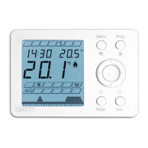
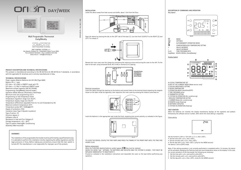
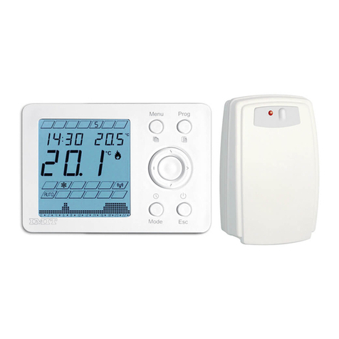
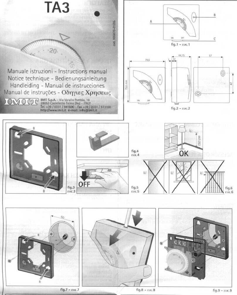
Imit TECHNO RT User manual

DESCRIZIONE PRODOTTO E SPECIFICHE TECNICHE PRODUCT DESCRIPTION AND TECHNICAL SPECIFICATIONS DESCRIPTION DU PRODUIT ET CARACTÉRISTIQUES TECHNIQUES
PRODUKTBESCHREIBUNG UND TECHNISCHE ANGABEN
Questo prodotto è realizzato secondo le norme EN 60730-2-9, ETSI EN 301 489-1
(RT R, RT VR), ETSI EN 300 200-2 (RT R, RT VR) in conformità con le direttive CE
applicabili ed è interamente fabbricato in Italia.
RT
: Alimentazione: Batterie (2x1,5V) - Uscita: relè ON-OFF
RT V
: Alimentazione: 230Vac, 50Hz - Uscita: relè ON-OFF
RT R
: Alimentazione: Batterie (2x1,5V) - Uscita: Radio 868.2 Mhz
RT VR
: Alimentazione: 230Vac, 50Hz - Uscita: Radio 868.2 Mhz
RT
RT R
RT V
RT VR
RT
RT V
RT R
RT VR
Classe ErP I (+1%) - EU 811/2013
Temperatura ambiente massima: 50°C
Campo di visualizzazione temperatura: 0°C÷39°C
Campo di regolazione temperatura: 5°C÷35°C
Risoluzione temperatura: 0,1°C
Differenziale temperatura: da 0,1°C a 2,0°C (standard 0,2°C)
Sonda di temperatura: NTC 100KΩ@25°C
Grado di protezione: IP20
Classe di isolamento: Tipo II (doppio isolamento)
Grado d’inquinamento: 2
Software: classe A
Resistenza al calore ed al fuoco: Categoria D
Temperatura di stoccaggio: -25÷60°C
Tensione nominale di tenuta ad impulso: 2,5kV
Montaggio: a parete
Installare il dispositivo lontano da fonti di calore e correnti d’aria, a circa
1,5m dal pavimento. Aprire il dispositivo premendo il dentino posto sul lato
inferiore della base (Fig.1 A). Ruotare il frontale verso l’alto (Fig.1 B) e
sollevarlo leggermente per sganciarlo (Fig.1 C).
RT R
RT
RT V
RT VR
RT
RT R
Per richiudere il dispositivo procedere come prima invertendo la sequenza
delle operazioni: accoppiare i lati superiori delle due parti (Fig.1 C) quindi
ruotare il frontale verso il basso (Fig.1 B) sino a far scattare il gancio
inferiore (Fig.1 A) sulla base.
SOSTITUZIONE BATTERIE
RT
RT R
I comandi sono costituiti da un anello a quattro posizioni identificate dalle
frecce ◄►▲▼ con un tasto centrale OK. Premere l’anello in corrispondenza
delle frecce per attivare un solo tasto alla volta. Premere il tasto OK al
centro. Usare i tasti freccia per modificare i valori di tempo e temperatura
o selezionare le opzioni, il tasto centrale OK normalmente conferma le
impostazioni.
PRIMA ACCENSIONE (Fig.5)
Impostare l’orologio
• Impostare il formato 24H o 12H con ▲▼, poi OK.
• Impostare l’ora con ▲▼, poi OK.
• Impostare i minuti con ▲▼, poi OK.
Il display visualizza OFF e l’orologio.
RT R
RT VR
MODO OFF (Fig.6)
La funzione antigelo è attiva.
Premere per 3 secondi:
▼per impostare l’orologio (come sopra).
▲per impostare il modo stagione Estate/Inverno (standard: INVERNO).
◄per passare da OFF al modo attivo e vice versa.
Premere per 10 secondi OK per entrare nel Menu Installatore.
MODO ATTIVO (Fig.7 e Fig.8)
La temperatura ambiente misurata è sempre in primo piano.
Premere OK per visualizzare in alto a destra l’orologio o la temperatura
impostata.
Premere ► per scegliere la temperatura Comfort (standard) o Economy (ECO).
Premere ▲ ▼ per modificare i valori impostati e memorizzati.
Standard Comfort : INVERNO = 20,0°C / ESTATE = 25,0°C
Standard ECO : INVERNO = 16,0°C / ESTATE = 28,0°C
MODO STAGIONE INVERNO
La temperatura Comfort è maggiore della temperatura Economy (t1>t2).
Quando Tamb < Tset si attiva il riscaldamento .
MODO STAGIONE ESTATE
La temperatura Comfort è minore della temperatura Economy (t1<t2).
Quando Tamb > Tset si attiva il raffrescamento .
COMUNICAZIONE RADIO
RT R
RT VR
MENU INSTALLATORE (Fig.9)
In modalità OFF premere per 10 secondi OK per entrare nel Menu Installatore.
Premere ◄ ► per scegliere le opzioni;
Premere ▲▼ per modificare i valori;
• AF = Soglia antigelo (standard 6.0°C);
• HYS = Differenziale temperatura (standard 0.2°C);
• OFS = Correzione offset temperatura (standard 0.0°C);
• °C = Selezione gradi Celsius/Farhenheit (standard Celsius);
• rAd = (solo per modelli RT R, RT VR) Premere ▲ per selezionare YES
e confermare premendo ancora ▲. Al termine della procedura di
abbinamento, il display visualizza “rdY” in caso di esito positivo,
“Err” in caso negativo;
• CLR = Premere ▲per selezionare YES e confermare premendo ancora ▲.
Attendere 4 secondi per reset automatico. Ripristina i valori di
fabbrica.
Premere OK per uscire dal menu installatore.
This product is manufactured in accordance with standards EN 60730-2-9,
ETSI EN 301 489-1 (RT R, RT VR), ETSI EN 300 200-2 (RT R, RT VR), in
accordance with applicable EC directives and it is entirely manufactured in Italy.
RT
: Power supply: Batteries (2x1,5V) - Output: relay ON-OFF
RT V
: Power supply: 230Vac, 50Hz - Output: relay ON-OFF
RT R
: Power supply: Batteries (2x1,5V) - Output: Radio 868.2 Mhz
RT VR
: Power supply: 230Vac, 50Hz - Output: Radio 868.2 Mhz
RT
RT R
RT V
RT VR
RT
RT V
RT R
RT VR
Class ErP I (+1%) - EU 811/2013
Maximum ambient temperature: 50°C
Temperature display range: 0°C÷39°C
Temperature regulation range: 5°C÷35°C
Temperature resolution: 0.1°C
Temperature differential: from 0.1°C to 2.0°C (standard 0.2°C)
Temperature probe: NTC 100KΩ@25°C
Degree of protection: IP20
Insulation class: Type II (double insulation)
Pollution degree: 2
Software: class A
Heat and fire resistance: Category D
Storage temperature: -25÷60°C
Rated impulse withstand voltage: 2.5kV
Installation: wall-mounting
Install the device away from heat sources and drafts, about 1.5m from the
floor. Open the device by pressing the small tab on the underside of the
base (Fig.1 A). Turn the front panel upwards (Fig.1 B) and lift it slightly to
release it (Fig.1 C).
RT R
RT
RT V
RT VR
RT
RT R
To close the device, proceed as before but reversing the sequence of operations:
match the upper sides of the two parts (Fig.1 C) then turn the front panel
downwards (Fig.1 B) until the lower hook clicks (Fig.1 A) on the base.
REPLACING THE BATTERIES
RT
RT R
The controls consist of a ring with four positions identified by the arrows
◄►▲▼ with a central button OK. Press the ring in correspondence with
the arrow to activate one button at a time. Press the OK button in the
centre. Use the arrow buttons to change the time and temperature values or
to select the options, the central OK button usually confirms the settings.
FIRST START-UP (Fig. 5)
Set the clock
• Set the format 24H or 12H using ▲▼, then OK.
• Set the hour using ▲▼, then OK.
• Set the minutes using ▲▼, then OK
OFF and the clock appear on the display.
RT R
RT VR
OFF MODE (Fig. 6)
The antifreeze function is active.
Press for 3 seconds:
▼to set the clock (as above).
▲to set the season mode Summer/Winter (standard: WINTER).
◄to go from OFF to ON and vice versa.
Press OK for 10 seconds to enter the Installer Menu.
ON MODE (Fig.7 and Fig.8)
The ambient temperature measured is always in the foreground.
Press OK to display the clock or the set temperature in the top right corner.
Press ► to select the temperature Comfort (standard) or Economy (ECO).
Press ▲ ▼ to change the set and stored values.
Standard Comfort : WINTER = 20.0°C / SUMMER = 25.0°C
Standard ECO : WINTER = 16.0°C / SUMMER = 28.0°C
WINTER MODE
The Comfort temperature is higher than the Economy temperature (t1>t2).
When Tamb < Tset (Room temperature < Set temperature), the heating is
activated .
SUMMER MODE
The Comfort temperature is lower than the Economy temperature (t1<t2).
When Tamb > Tset (Room temperature > Set temperature), the cooling is
activated .
RADIO COMMUNICATION
RT R
RT VR
INSTALLER MENU (Fig. 9)
On OFF mode, press OK for 10 seconds to enter the Installer Menu.
Press ◄ ► to select the options;
Press ▲▼ to change the values;
• AF = Antifreeze threshold (standard 6.0°C);
• HYS = Temperature differential (standard 0.2°C);
• OFS = Temperature offset correction (standard 0.0°C);
• °C = Select degrees Celsius/Fahrenheit (standard Celsius);
• rAd = (only RT R, RT VR) Press ▲ to select YES and confirm bypressing
▲ again. At the end of the pairing procedure, “rdY” will
appear on the display if it was successful, “Err” if it was unsuccessful;
• CLR = Press ▲to select YES and confirm by pressing ▲ again. Wait 4
seconds for the automatic reset. Reset factory values.
Press OK to exit the installer menu.
Ce produit est réalisé selon les normes EN 60730-2-9 , ETSI EN 301 489-1
(RT R, RT VR), ETSI EN 300 200-2 (RT R, RT VR), en accord avec les directives
CE applicables et entièrement fabriqué en Italie.
RT
: Alimentation: Piles (2x1,5V) - Sortie : relais ON-OFF
RT V
: Alimentation: 230Vac, 50Hz - Sortie : relais ON-OFF
RT R
: Alimentation: Piles (2x1,5V) - Sortie : Radio 868.2 Mhz
RT VR
: Alimentation: 230Vac, 50Hz - Sortie : Radio 868.2 Mhz
RT
RT R
RT V
RT VR
RT
RT V
RT R
RT VR
Classe ErP I (+1%) - EU 811/2013
Température ambiante maximale : 50°C
Champ de visualisation de la température : 0°C÷39°C
Champ de réglage de la température : 5°C÷35°C
Résolution de la température : 0,1°C
Ecart de températur : de 0,1°C à 2,0°C (standard 0,2°C)
Sonde de température : NTC 100KΩ@25°C
Degré de protection: IP20
Classe d’isolation: Type II (double isolation)
Degré de pollution : 2
Logiciel : classe A
Résistance à la chaleur et au feu : Catégorie D
Température de stockage: -25÷60°C
Tension nominale de tenue aux chocs : 2,5kV
Montage : au mur
Installer le dispositif loin des sources de chaleur et des courants d’air, à
environ 1,5 m du sol. Ouvrir le boîtier en appuyant sur la languette située sur
le côté inférieur de la base (Fig. 1 A). Tourner la partie frontale vers le haut
(Fig. 1 B) et la soulever légèrement pour la décrocher (Fig. 1 C).
RT R
RT
RT V
RT VR
RT
RT R
Pour refermer le dispositif, procéder comme dit précédemment en inversant
l’ordre des opérations : accrocher les côtés supérieurs des deux parties (Fig. 1 C)
puis tourner la partie frontale vers le bas (Fig. 1 B) jusqu’à accrocher le crochet
inférieur (Fig. 1 A) à la base.
REMPLACEMENT DES BATTERIES
RT
RT R
Les commandes sont composées d’une bague à quatre positions identifiées
par les flèches ◄►▲▼ avec une touche centrale OK. Presser la bague au
niveau des flèches pour activer une seule touche à la fois. Appuyer sur la
touche OK au centre. Utiliser les touches flèche pour modifier les valeurs de
temps et de température ou sélectionner les options, la touche centrale OK
confirme les paramètres.
PREMIER DÉMARRAGE (Fig. 5)
Programmer l’horloge
• Régler le format 24H ou 12H avec ▲▼, puis OK
• Régler l’heure avec ▲▼, puis OK.
• Régler les minutes avec▲▼, puis OK.
L’écran affiche OFF et l’horloge.
RT R
RT VR
MODE OFF (Fig. 6)
La fonction antigel est activée.
Appuyer pendant 3 secondes :
▼pour programmer l’horloge (comme indiqué plus haut).
▲pour programmer le mode saison Été/Hiver (standard : HIVER).
◄pour passer de OFF au mode activé et vice-versa.
Presser 10 secondes la touche OK pour accéder au Menu Installateur.
MODE DE FONCTIONNEMENT (Fig. 7 et Fig. 8)
La température ambiante mesurée est toujours en premier plan.
Appuyer sur OK pour visualiser en haut à droite l’horloge ou la température
programmée.
Presser ► pour choisir la température Comfort (standard) ou Economy (ECO).
Presser ▲ ▼ pour modifier les valeurs programmées et mémorisées.
Standard Comfort : HIVER = 20,0°C / ÉTÉ = 25,0°C
Standard ECO : HIVER = 16,0°C / ÉTÉ = 28,0°C
MODE SAISON HIVER
La température Comfort est plus haute que la température Economy (t1>t2).
Le chauffage s’active quand Tamb < Tset .
MODE SAISON ÉTÉ
La température Comfort est plus basse que la température Economy (t1<t2).
La climatisation s’active quand Tamb > Tset .
COMMUNICATION RADIO
RT R
RT VR
MENU INSTALLATEUR (Fig. 9)
En mode OFF, presser pour 10 secondes la touche OK pour accéder au Menu
Installateur.
Presser ◄ ► pour sélectionner les options;
Presser ▲▼ pour modifier les valeurs;
• AF = Seuil antigel (standard 6.0°C);
• HYS = Ecart de température (standard 0.2°C);
• OFS = Correction offset température (standard 0.0°C);
• °C = Sélection degrés Celsius/Fahrenheit (standard Celsius);
• rAd = (seulement RT R, RT VR) Presser ▲ pour sélectionner YES et
confirmer en pressant de nouveau ▲. À la fin de la procédure de
couplage, l’écran affiche le message “rdY” en cas de résultat
positif, “Err” en cas de résultat négatif;
• CLR = Presser ▲pour sélectionner YES et confirmer en pressant de
nouveau ▲. Attendre 4 secondes pour la réinitialisation
automatique. Réinitialiser les valeurs d’usine.
Presser OK pour quitter le menu installateur.
Dieses Produkt ist gemäß den Richtlinien EN 60730-2-9, ETSI EN 301 489-1
(RT R, RT VR), ETSI EN 300 200-2 (RT R, RT VR), in Übereinstimmung mit den
geltenden EG-Richtlinien und vollständig in Italien hergestellt worden.
RT
: Versorgung: Batterien (2x1,5V) - Ausgang: Relais ON-OFF
RT V
: Versorgung: 230Vac, 50Hz - Ausgang: Relais ON-OFF
RT R
: Versorgung: Batterien (2x1,5V) - Ausgang: Funk 868.2 Mhz
RT VR
: Versorgung: 230Vac, 50Hz - Ausgang: Funk 868.2 Mhz
RT
RT R
RT V
RT VR
RT
RT V
RT R
RT VR
Klasse ErP I (+1%) - EU 811/2013
Maximale Umgebungstemperatur: 50°C
Anzeigefeld der Temperatur 0°C÷39°C
Einstellungsfeld der Temperatur: 5°C÷35°C
Temperaturauflösung: 0,1°C
Temperaturdifferenz: von 0,1°C bis 2,0°C (Standard 0,2°C)
Temperaturfühler: NTC 100KΩ@25°C
Schutzgrad: IP20
Isolierungsklasse: Typ II (doppelte Isolierung)
Verschmutzungsgrad: 2
Software: Klasse A
Hitze- und Feuerbeständigkeit Kategorie D
Lagertemperatur: -25÷60°C
Nennspannung der Dichtung mit Impuls: 2,5kV
Montage: an der Wand
Das Gerät weit entfernt von Wärmequellen und Zugluft, etwa 1,5 m über dem
Boden installieren. Das Gerät durch Drücken des Zahns auf der Unterseite der
Basis (Abb.1 A) öffnen. Die Frontplatte nach oben (Abb. 1 B) drehen und sie
leicht anheben, um sie zu lösen (Abb. 1 C).
RT R
RT
RT V
RT VR
RT
RT R
Um das Gerät wieder zu schließen, ist wie zuvor, jedoch in umgekehrter
Reihenfolge der Verfahren vorzugehen: die oberen Seiten der beiden Teile
(Abb.1 C) verbinden, anschließend die Frontplatte nach unten drehen (Abb.1 B),
bis der untere Haken (Abb.1 A) auf der Basis einrastet.
BATTERIEAUSTAUSCH
RT
RT R
Die Steuerbefehle bestehen aus einem Ring mit vier Positionen, die durch
die Pfeile ◄►▲▼ mit einer mittleren OK-Taste gekennzeichnet werden.
Den der Pfeile entsprechenden Ring drücken, um jeweils nur eine Taste zu
aktivieren. Die OK-Taste in der Mitte drücken. Die Pfeiltasten verwenden, um
die Zeit- und Temperaturwerte zu verändern oder die Optionen auszuwählen.
Die mittige OK-Taste bestätigt in der Regel die Einstellungen.
ERSTE ZÜNDUNG (Abb. 5)
Einstellung der Uhr
•
Das Format 24H oder 12H mit ▲▼einstellen, anschließend auf OK drücken.
• Die Uhr mit ▲▼einstellen, anschließend auf OK drücken.
• Die Minuten mit ▲▼einstellen, anschließend auf OK drücken.
Das Display zeigt OFF und die Uhr an.
RT R
RT VR
OFF-MODUS (Abb. 6)
Die Frostschutzfunktion ist aktiv.
Für 3 Sekunden drücken:
▼um die Uhr einzustellen (wie oben).
▲um den Sommer-/Wintermodus einzustellen (Standard: WINTER).
◄um vom OFF-Modus in den aktiven Modus zu schalten oder umgekehrt.
10 Sekunden auf OK drücken, um das Installationsmenü aufzurufen.
AKTIVER MODUS (Abb.7 und Abb.8)
Die gemessene Umgebungstemperatur steht immer im Vordergrund.
Auf OK drücken, um im oberen rechten Abschnitt die Uhr oder die eingestellte
Temperatur anzuzeigen.
►drücken, um die Comfort-Temperatur (Standard) oder Economy-Temperatur
(ECO) auszuwählen.
▲▼ drücken, um die eingestellten und gespeicherten Werte zu verändern.
Standard-Comfort: WINTER = 20,0°C / SOMMER = 25,0°C
Standard ECO: WINTER = 16,0°C / SOMMER = 28,0°C
WINTER-MODUS
Die Comfort-Temperatur ist höher als die Economy-Temperatur (t1>t2).
Wenn Tamb < Tset (Umgebungstemperatur < Eingestellte Temperatur), wird
die Heizung aktiviert.
SOMMER-MODUS
Die Comfort-Temperatur ist niedriger als die Economy-Temperatur (t1<t2).
Wenn Wenn Tamb > Tset (Umgebungstemperatur > Eingestellte Temperatur),
wird die Abkühlung aktiviert.
FUNK-KOMMUNIKATION
RT R
RT VR
INSTALLATIONSMENÜ (Abb. 9)
Im OFF-Modus ist 10 Sekunden auf OK zu drücken, um das Installationsmenü
aufzurufen.
◄ ► drücken, um die Optionen auszuwählen;
▲▼ drücken, um die Werte zu modifizieren;
• AF = Frostschutzschwelle (Standard 6.0°C);
• HYS = Temperaturdifferenz (Standard 0.2°C);
• OFS = Korrektur Offset-Temperatur (Standard 0.0°C);
• °C = Auswahl Grad Celsius/Fahrenheit (Standard Celsius);
• rAd = (nur RT R, RT VR) ▲ drücken, um YES auszuwählen und
durch Drücken von ▲ bestätigen. Nach Abschluss des
Verbindungsverfahrens zeigt das Display «rdY» an, falls ein positives
Ergebnis vorliegt, und «Err», falls ein negatives Ergebnis erzielt
worden ist;
• CLR = ▲drücken, um YES auszuwählen und durch Drücken von ▲
bestätigen. 4 Sekunden auf das automatische Reset warten. Die
Werte der Werkseinstellung wieder herstellen.
Auf OK drücken, um das Installationsmenü zu verlassen.
ATTENZIONE! Si raccomanda di eseguire l’installazione del
dispositivo rispettando scrupolosamente le norme di sicurezza
e le disposizioni di legge vigenti. Prima di effettuare qualsiasi
collegamento, accertarsi che l’interruttore generale sia stato
disattivato.
WARNING! It is recommended to install the device in strict
accordance with the safety regulations and laws in force. Before
making any connection, make sure that the main switch is off.
ATTENTION : Nous recommandons d’effectuer l’installation du
dispositif en respectant scrupuleusement les normes de sécurité
et les dispositions de loi en vigueur. Avant d’effectuer tout
branchement, vérifier que l’interrupteur général est désactivé.
ACHTUNG! Es empfiehlt sich, die Installation des Gerätes unter
strenger Einhaltung der geltenden Sicherheitsstandards und der
geltenden Gesetze auszuführen. Bevor eine Verbindung hergestellt
wird, ist sicherzustellen, dass der Hauptschalter deaktiviert worden ist.
INSTALLAZIONE INSTALLATION INSTALLATION INSTALLATION
DESCRIZIONE COMANDI E FUNZIONAMENTO DESCRIPTION OF CONTROLS AND OPERATION DESCRIPTION DES COMMANDES ET FONCTIONNEMENT BESCHREIBUNG DER STEUERBEFEHLE UND DES BETRIEBS
IT EN FR DE
Alimentazione: Batterie Alcaline 2x1,5V LR03 (Tipo AAA)
Durata batterie > 1 anno
Alimentazione: 230Vac, 50Hz
Potenza massima assorbita: < 0.5W
Mantenimento orologio in assenza di tensione d’alimentazione >12h
Portata massima contatti: 5A(1A) 250VAC
Tipo di azione: 1B
Fissare la base alla parete, usando l’interasse orizzontale (Fig.2 A-A)
o diagonale Fig.2 B-B).
Rimuovere la protezione interna che copre i morsetti svitando la
vite (Fig.2 C) e ruotando il coperchio verso l’alto. Fissare la base
alla parete, usando l’interasse orizzontale (Fig.2 A-A) o diagonale
(Fig.2 B-B). Infilare i cavi attraverso l’apertura sul fondo e collegarli
alla morsettiera (Fig.4) quindi riposizionare il coperchio interno
riavvitando la vite (Fig.2 C).
Inserire le batterie nell’apposita sede all’interno del frontale (Fig.3).
Quando il simbolo lampeggia (batterie scariche) occorre
provvedere alla loro sostituzione. Procedere come indicato nelle
istruzioni d’installazione (Fig.1 e Fig.3). Rimontare il coperchio
sulla base prima di effettuare qualsiasi operazione.
Effettuare l’abbinamento con il ricevitore radio RCV tramite il
parametro “rAd” del menu installatore. La procedura è effettuata in
fabbrica ma è possibile ripeterla (ad esempio in caso di sostituzione
di un dispositivo). Predisporre prima il ricevitore RCV seguendo le
sue istruzioni.
Normalmente il display mostra il simbolo fisso (Fig.8). Se
lampeggia, verificare i dispositivi, provare a ripetere la procedura di
abbinamento oppure modificarne la posizione.
Frequenza di funzionamento: 868.2 Mhz
Categoria del ricevitore: 2
Duty cycle trasmettitore < 1%
Portata: 300 m in campo aperto, 20 m all’interno di edifici
Tipo di antenna: interna, su circuito stampato
Operating frequency: 868.2 Mhz
Category of the receiver: 2
Duty cycle of the transmitter < 1%
Capacity: 300 m outdoors, 20 m indoors
Type of antenna: internal, on PCB
Power supply: 2x1.5V LR03 Alkaline batteries (AAA type)
Battery life > 1 year
Power supply: 230Vac, 50Hz
Maximum power absorbed: < 0.5W
Maintenance of clock in the absence of supply voltage >12h
Maximum capacity of the contacts: 5A(1A) 250VAC
Type of action: 1B
Fréquence de fonctionnement : 868.2 Mhz
Catégorie du récepteur : 2
Duty cycle trasmettitore < 1%
Portée : 300 m en champ libre, 20 m à l’intérieur des bâtiments
Type d’antenne : interne, sur circuit imprimé
Alimentation: Piles alcalines 2x1,5V LR03 (AAA)
Durée des piles > 1 an
Alimentation: 230Vac, 50Hz
Puissance maximale absorbée : < 0.5W
Maintien de l’horloge en l’absence de courant >12 heures
Débit maximal des contacts : 5A(1A) 250VAC
Type d’action : 1B
Betriebsfrequenz: 868.2 Mhz
Kategorie des Empfängers: 2
Betriebszyklus Druckgeber < 1%
Leistung: 300 m auf offenem Feld, 20 m im Inneren von Gebäuden
Antennentyp: intern, auf Leiterplatte
Versorgung: Alkali-Batterien 2x1,5V LR03 (Typ AAA)
Batterielaufzeit > 1 Jahr
Versorgung: 230Vac, 50Hz
Maximale Leistungsaufnahme: < 0.5W
Beibehaltung der Uhr bei Abwesenheit der Versorgungsspannung > 12 Std
Maximale Kontaktleistung: 5A(1A) 250VAC
Art des Verfahrens: 1B
Remove the internal protection covering the terminals by
unscrewing the screw (Fig.2 C) and turning the cover upwards.
Attach the base to the wall, using the horizontal (Fig.2 A-A) or
diagonal distance (Fig.2 B-B). Insert the cables through the opening
at the bottom and connect them to the terminal board (Fig.4) then
replace the internal cover and tighten the screw (Fig.2 C).
Enlever la protection interne qui protège les bornes en dévissant la
vis (Fig. 2 C) et en tournant le couvercle vers le haut. Fixer la base
au mur en utilisant l’entraxe horizontal (Fig. 2 A-A) ou diagonal
(Fig. 2 B-B). Faire passer les câbles à travers l’ouverture présente
sur le fond et les brancher à la barrette de raccordement (Fig. 4)
puis repositionner le couvercle interne en revissant la vis (Fig. 2 C).
Die interne Schutzvorrichtung, die die Klemmen abdeckt, entfernen, indem
die Schraube (Abb.2 C) gelöst und der Deckel nach oben gedreht wird. Die
Basis an der Wand befestigen, indem der horizontale (Abb.2 A-A) oder
diagonale Achabstand
(Abb.2 B-B) verwendet wird. Die Kabel durch die
Öffnung auf der Unterseite einführen und sie mit der Anschlussleiste
(Abb. 4) verbinden und anschließend den inneren Deckel neu
positionieren, indem die Schraube (Abb. 2 C) angeschraubt wird.
Insert the batteries in the front panel (Fig.3). Insérer les piles dans le logement à l’intérieur de la partie frontale
(Fig. 3). Die Batterien in den vorgesehenen Sitz innerhalb der Frontseite
(Abb. 3) einfügen.
When the symbol flashes (batteries low) it is necessary to
replace them. Proceed as indicated in the installation instructions
(Fig. 1 and Fig.3). Put the cover back on the base before performing
any operation.
Quand le symbole clignote (piles épuisées) il faut les
remplacer. Procéder en suivant les instructions de la notice
d’installation (Fig. 1 et Fig. 3). Remonter le couvercle sur la base
avant d’effectuer une quelconque opération.
Wenn das Symbol blinkt (schwache Batterien), ist es
erforderlich, für ihren Austausch zu sorgen. Dafür ist wie in den
Installationsanweisungen (Abb. 1 und Abb.3) vorzugehen. Den Deckel
wieder auf der Basis anbringen, bevor ein Verfahren ausgeführt wird.
Pair with the radio receiver RCV by means of the “rAd” parameter
in the installer menu. The procedure is performed at the factory but
it is possible to repeat it (for example when a device is replaced).
First prepare the receiver RCV by following the instructions.
Effectuer le couplage avec le récepteur radio RCV par le paramètre
du paramètre “rAd” du menu installateur. La procédure est
effectuée en usine mais elle peut être répétée (ex.: en cas de
substitution d’un dispositif). Préparer d’abord le récepteur RCV en
suivant ses instructions.
Die Verbindung mit dem Funk-Empfänger RCV mittels Parameter
«rAd» des Installations-Menüs herstellen. Das Verfahren wird im
Werk ausgeführt, lässt sich jedoch wiederholen (beispielsweise im
Fall eines Ersatzes eines Geräts). Zunächst den Empfänger RCV
gemäß den Anweisungen ausrichten.
Normally, the display shows the symbol fixed (Fig.8). If
flashes, check the devices, try to repeat the pairing procedure or
change its position.
L’écran affiche le symbole fixe (Fig. 8). Si le symbole
clignote, vérifier les dispositifs, essayer de répéter la procédure de
couplage ou en modifier la position.
In der Regel zeigt das Display das feststehende Symbol (Abb.8).
Falls blinkt, sind die Vorrichtungen zu prüfen, ist zu versuchen,
das Verbindungsverfahren zu wiederholen oder die Position zu
verändern.
Attach the base to the wall, using the horizontal (Fig.2 A-A) or
diagonal distance (Fig.2 B-B).
Die Basis an der Wand befestigen, indem der horizontale (Abb.2 A-A)
oder diagonale Achabstand (Abb.2 B-B) verwendet wird.
Fixer la base au mur en utilisant l’entraxe horizontal (Fig. 2 A-A)
ou diagonal (Fig. 2 B-B).
Fig. 1
AB
C
Fig. 5
Fig. 6
Fig. 9
NC
C
NO
NC
C
NO
C
NC
NO
Fig. 4
NC
C
NO
NC
C
NO
C
NC
NO
LN
N
L
230 Vac
LN
N
L
230 Vac
RT
RT V
RT VR
Fig. 7
RT
RT V
Fig. 2 Fig. 3
AA
B
B
A-A=60mm
B-B=90mm
C
+
+
-
-
RT
RT R
Fig. 8
RT R
RT VR
IMIT CONTROL SYSTEM s.r.l.
Via Varallo Pombia,19 - Castelletto Sopra Ticino (NO)
Tel (+39)0331941600 - Fax (+39)0331973100
Termostato Ambiente
Room Thermostat
Thermostat ambiant
Raumtermostat
Termostato Ambiente
Omgevingsthermostaat
Θερμοστάτης Περιβάλλοντος
Комнатный термостат
076455 Rev1116
RT
Table of contents
Other Imit Thermostat manuals
Popular Thermostat manuals by other brands

Elko
Elko T2300 user guide

Jackson Systems
Jackson Systems T-32-TS Touchscreen Thermostat user manual

Aube Technologies
Aube Technologies TH140-28 Installation and user guide

Sinope
Sinope TH1400WF installation guide

Honeywell
Honeywell FocusPRO 5000 quick guide

Kermi
Kermi WRT Instructions for installation and use