ThermoTec AeroFlow MINI 650 User manual

AeroFlow®-Elektroheizung Bedienungsanleitung
Chauffage électrique AeroFlow® Mode d‘emploi
AeroFlow® electronic heater user manual
Allgemeine Hinweise
Anleitung Montage Wandhalterung
Anleitung Funkthermostat (Empfänger)
Anleitung Funkthermostat (Sender)
Anleitung Displayregler
Garantiebegleitschein
Remarques générales
Instructions de montage du support mural
Instructions relatives au thermostat sans fil (récepteur)
Instructions relatives au thermostat sans fil (émetteur)
Instructions relatives au régulateur d‘ambiance
Bordereau de garantie
General Information
Manual on assembly of wall bracket
Manual wireless thermostat (receiver)
Manual wireless thermostat (transmitter)
Manual for display controller
Guarantee Certificate
Seite 2
Seite 3
Seite 3
Seite 3
Seite 4-6
Seite 19
Page 12
Page 13
Page 13
Page 13
Page 14-16
Page 19
Page 7
Page 8
Page 8
Page 8
Page 9-11
Page 19
Customers of the United Kingdom and Ireland will f ind easy installat ion and intruct ions video also available here:
htt p://www.electrorad.co.uk/aerof low-instruct ion-videos

7. Gerätereinigung
Schalten Sie vor jeder Reinigung das Heizgerät aus und lassen dieses vollständig
abkühlen. Wischen Sie das Heizgerät nur mit einem weichen feuchten Tuch ab
und verwenden Sie keine chemischen Reinigungsmittel oder Scheuermilch. Zum
Säubern der Lamellen kann eine entsprechend konzipierte Reinigungsbürste
verwendet werden (nicht im Lieferumfang enthalten). Ein passendes Produkt
bieten wir Ihnen in unserem Online-Shop unter Zubehör zum Kauf an.
8. Entsorgungshinweise
Entsorgung von Altgeräten in Deutschland
Die mit nebenstehenden Symbol gekennzeichneten Geräte
dürfen nicht mit dem Hausmüll entsorgt werden. Als Hersteller
sorgen wir im Rahmen der Produktionsverantwortung für eine
umweltgerechte Behandlung und Verwertung der Altgeräte. Weitere Infor-
mationen zum Sammlung und Entsorgung erhalten Sie über Ihre Kommune.
Entsorgung außerhalb Deutschlands
Entsorgen Sie diese Geräte fach- und sachgerecht nach den örtlich geltenden
Vorschriften und Gesetzen.
9. Garantiebedingungen
Für dieses Produkt übernehmen wir 30 Jahre Funktionsgarantie auf den Bereich
der Wärmeerzeugung und Bedienbarkeit des Grundgeräts sowie 2 Jahre
Garantie auf die Regelungstechnik, die Ersatzteile und das Zubehör. Im Übrigen
gilt die gesetzliche Gewährleistung. Unsere Garantiebedingungen regeln die
zusätzlichen Garantieleistungen, die neben die gesetzlichen Gewährleistungs-
ansprüche des Kunden treten. Die Garantiebedingungen gelten nur für solche
Geräte, die vom Endkunden als Neugeräte erworben werden. Eine Garantie-
verpflichtung kommt nicht zustande, soweit der Endkunde ein gebrauchtes
Gerät oder ein neues Gerät seinerseits von einem anderen Endkunden erwirbt.
Die Garantieleistung wird erbracht, wenn an unseren Heizgeräten und dem
Zubehör ein Herstellungs- und/oder Materialfehler während der Garantiezeit
auftritt. Innerhalb der Garantiezeit, die mit dem Anlieferungstag beginnt,
beseitigen wir kostenlos alle anfallenden Funktionsfehler, die nachweisbar auf
Materialfehler oder auf mangelnde Ausführung zurückzuführen sind. Unsere
Garantie beinhaltet den kostenlosen Austausch von defekten Teilen sowie die
kostenlosen Ersatzteile während der Garantiezeit. Wir haften nur, wenn die
Funktion des Heizgerätes beeinträchtigt ist und der Defekt nicht durch
fahrlässige, vorsätzliche oder unsachgemäße Behandlung, Gewaltanwendung,
den Transport, Fehlgebrauch, Anschließen an falsche Netzspannungen,
Nichtbeachtung der sachgemäßen Bedienungs- oder Montagehinweise,
unsachgemäße Reinigung bzw. Korrosionsschäden durch aggressives Wasser,
chemische und/oder elektrochemische Einwirkungen oder den normalen
Verschleiß verursacht wurde. Die Garantie erlischt, wenn am Gerät Eingriffe oder
Reparaturversuche durch nicht von uns autorisierte Stellen vorgenommen
wurden.Bitte beachten Sie, dass ein Auseinanderbauen des Heizgeräts durch
den Kunden oder durch Dritte grundsätzlich nicht zulässig ist. Bei
Zuwiderhandlung besteht kein Garantieanspruch. Der mögliche Austausch des
modularen Heizgerät-Seitenteils (z.B. bei Änderung der Regelungstechnik)
und/oder die mögliche Kürzung des Anschlusskabels (z.B. bei Entfernung des
Schuko-Steckers zwecks bedingter Herstellung eines Festanschlusses) führt nicht
zu einem Garantieverlust, insofern hierbei – über das notwendige Maß der
durchzuführenden Änderung hinaus – kein Eingriff auf bzw. eine Manipulation
von elektronischen Bauteilen erfolgt und die entsprechend zulässigen Arbeiten
durch einen qualifizierten Fachmann ausgeführt werden. Die Garantieleistung
umfasst die sorgfältige Prüfung des Heizgeräts oder des Zubehörs, wobei
zunächst ermittelt wird, ob ein Garantieanspruch besteht. Im Garantiefall
entscheiden allein wir, auf welche Art und Weise der Fehler behoben wird. Es
steht uns frei, ein Heizgerät oder Zubehörteil auszutauschen oder eine Reparatur
auszuführen. Während der Garantiezeit übernehmen wir im Rahmen der
Reichweite dieser Garantie sämtliche Material-, Montage- und Transportkosten.
Über die vorstehend zugesagte Garantieleistung hinweg kann der Endkunde
nach dieser Garantie keine Ansprüche wegen mittelbarer Schäden oder
Folgeschäden, die durch das Gerät verursacht werden, insbesondere auf Ersatz
außerhalb des Geräts entstandener Schäden, geltend machen. Gesetzliche
Ansprüche des Kunden uns gegenüber bleiben unberührt. Garantieansprüche
sind vor Ablauf der Garantiezeit, innerhalb von einer Woche, nachdem der
Mangel erkannt wurde, bei uns anzumelden. Hierzu verwenden Sie bitte den
dieser Anleitung beigefügten „Garantiebegleitschein“ und senden uns diesen
vollständig ausgefüllt auf dem Postweg an die aufgeführte Adresse oder als
elektronisches Formular per E-Mail an unsere genannte E-Mail-Adresse zu.
Allgemeine Hinweise
1. Sicherheitshinweise
Bitte lesen Sie die Bedienungsanleitung Ihrer neuen AeroFlow®- Elektroheizung
und die hier aufgeführten Informationen aufmerksam durch. Bewahren Sie
diese Anleitung sorgfältig auf und geben Sie diese gegebenenfalls an
Nachbesitzer weiter. Ihre neu erworbene Elektroheizung ist nur zum Erwärmen
innerhalb geschlossener Räume geeignet. Schadhafte Geräte (z.B. beschädigte
Anschlussleitung) dürfen nicht betrieben werden. Unsere Flächen-
speicherheizung ist bei sachgerechter Montage nach der jeweils geltenden IP-
Schutzart (International Protection Code – hier: geschützt gegen Sprühwasser)
geprüft. In der festverlegten elektrischen Installation ist eine Trennvorrichtung
mit mindestens 3mm Kontaktöffnung an jedem Pol (z.B. Sicherungsautomat,
Fehlerstrom-Schutzschalter) vorzusehen. Stoffe, die zur Entzündung oder
thermischen Zersetzung neigen (z.B. Kleber von Bodenbelägen), dürfen nur
verwendet werden, wenn sichergestellt ist, dass das Heizgerät auf
Raumtemperatur abgekühlt ist. Das Heizgerät darf nicht unmittelbar unterhalb
einer Wandsteckdose aufgestellt werden. Das Heizgerät ist nicht dafür
bestimmt, durch Personen (einschließlich Kinder) mit eingeschränkten
Wahrnehmungsfähigkeiten oder mangels Erfahrung und/ oder mangels Wissen
benutzt zu werden. Es sei denn, sie werden durch eine für ihre Sicherheit
zuständige Person beaufsichtigt oder erhielten von ihr Anweisungen, wie das
Heizgerät zu benutzen ist. Kinder sollen beaufsichtigt werden um
sicherzustellen, dass sie nicht mit dem Heizgerät spielen.
2. Elektrischer Anschluss
Ihre AeroFlow®- Elektroheizung ist für den Festanschluss an Wandanschluss-
dosen oder den Betrieb an Steckdosen geeignet. Bei der Installation über eine
Wandanschlussdose ist zwingend ein Elektroinstallateur hinzuzuziehen. Wenn
die Netzanschlussleitung eines Heizgerätes beschädigt wird, muss diese durch
uns oder einen entsprechend qualifizierten Elektroinstallateur ersetzt werden,
um Gefährdungen und weitere Schäden zu vermeiden. Das Heizgerät darf nur
mit Thermostat direkt am Heizkörper oder mit einer externen Steuerung
betrieben werden. Die Heizungsregelung muss stets über einen geeigneten
Raumthermostat erfolgen.
3. Montage
Unsere Geräte werden horizontal an der Wand montiert. Eine Befestigung an
der Decke ist nicht zulässig. Das Heizgerät sollte in der Regel unter einem Fenster
oder an einer Außenwand montiert werden. Bitte achten Sie darauf, dass das
Heizgerät möglichst frei in den Raum strahlen kann. Unsere detaillierten
Montageinformationen finden Sie auf Seite 3.
4. Heizbetrieb
Das Heizgerät wird über den extern oder intern angebrachten Raum-
thermostaten geregelt. Eine höhere Einstellung bedeutet eine längere
Einschaltdauer am Heizgerät. Bitte beachten Sie hierzu die Bedienungsanleitung
der Raumthermostate auf den folgenden Seiten. Es ist möglich, das bei
Erstinbetriebnahme eine leichte Geruchsentwicklung entstehen kann, da einige
Werkstoffe noch ausgeheizt werden müssen. Dies stellt keine Gefährdung dar
und verläuft sich nach einiger Zeit restlos. Bitte lüften Sie die Räume
gegebenenfalls gut durch. In seltenen Fällen kann es zur Geräuschbildung in
Form von knacken kommen, was durch wärmebedingte Materialbewegungen
verursacht wird, die unbedenklich sind.
5. Überhitzungsschutz
Zu Ihrer Sicherheit ist das Heizgerät mit einem in der Heizung integrierten
Temperaturschalter ausgerüstet. Bei unzulässiger Erwärmung der Heizung (z.B.
durch Verhängen oder Zustellen des Heizgeräts), schaltet das Heizgerät
automatisch ab. Das Verhängen des Heizgeräts (z.B. durch Handtücher) im
laufenden Betrieb ist nicht zulässig. Brandgefahr! Eventuell daraus resultierende
Defekte an einem Temperaturschalter und die hieraus entstehenden Kosten für
die Reparatur trägt ausschließlich der Verursacher. Einen für unsere Heizgeräte
passenden Handtuchhalter bieten wir Ihnen in unserem Online-Shop unter
Zubehör zum Kauf an.
6. Störungen
Wenn das Heizgerät keine Wärme abgibt, prüfen Sie bitte, ob die Voreinstellung
des Thermostaten auf die gewünschte Temperatur ausgerichtet ist. Darüber
hinaus ist grundsätzlich zu prüfen, dass die örtliche Stromverteilung
eingeschaltet bzw. die Sicherung in Ordnung ist. Bei derartigen Störungen
wenden Sie sich bitte an Ihre Elektrofachwerkstatt. Im Fall einer an uns
gerichteten Reklamation wird für die Auftragsbearbeitung die Seriennummer
des Gerätes benötigt. Diese Angabe finden Sie auf dem Typenschild.
Einlernen eines Domotiksenders
Drücken Sie am Empfänger länger als 3 Sekunden die Taste, bis die Kontroll-
leuchte zu blinken beginnt.
Zwei Betriebsarten sind möglich:
1. Langsames Blinken: Ein/Aus Schalter
2. Schnelles Blinken: Impulsgeber
Umschalten der Modi
Drücken Sie kurz die Taste am Empfänger. Bringen Sie den
Sender in den Konfigurationsmodus. Überprüfen Sie, dass
die Kontrollleuchte am Empfänger nicht mehr blinkt.
Zuordnungen löschen
Zum Löschen aller zugeordneten Produkte drücken Sie die Taste des Empfängers
ca. 30 Sekunden, bis die Kontrollleuchte kurz aufblinkt. Alle Sender sind nun
gelöscht.
Funktionsweise
Bidirektionales Funkprotokoll auf Funkfrequenz 868 Mhz. Die Reichweite beträgt
100 - 300 m (wenn Hindernisfrei). Platzierung an der Wand oder mobil im Raum.
Einstellungen
Drehregler für Ein/Aus und Grundeinstellungen
Einstelltasten + / - mit programmierbaren Einstellungen für:
- Tages-/Wochenprogrammierung
- Erkennen von geöffneten Fenstern
- Präsenzmelder (mit zusätzlichem Bewegungsmelder)
- Raumtemperaturregelung mit Displayanzeige
- Akustisches Signal beim Ein/Ausschalten
- Anzeige der Umgebungstemperatur
- Anzeige Stromverbrauch (kWh) der zugeordneten Elektroheizgeräte
- Ferienprogramm
- Winterzeit
Genaue Informationen über die Einstellungen des Funksenders entnehmen Sie
bitte der im gegebenen Fall beiliegenden Beschreibung des Funkthermostat
selbst.
Fenster Offen-Erkennung
Heizkörper mit X3D-Funkempfänger müssen zur Erfüllung der EU-Richtlinie
2009/125/EG mit einer Funktion zur vorübergehenden Heizkörper-Abschaltung
ausgestattet werden. Um das zu gewährleisten, können Sie von DELTA DORE
Funk-Öffnungsmelder „DO BL Tyxal+“ (Art.Nr. 6412288) oder „MDO BL Tyxal+“
(Art.Nr. 6412305) erwerben. Eine Anleitung wird mit dem Melder mitgeliefert.
Da wir diese Artikel nicht in unserem Programm führen, können wir zur
Einrichtung leider keine Hilfestellung anbieten.
Zur Wandmontage darf nur die mitgelieferte Wandhalterung verwendet
werden! Für die Montage und den Betrieb in Feuchträumen sind die aktuellen
Vorschrift en nach VDE 0100 Teil 701 unbedingt einzuhalten.
Das Gerät darf nicht unmittelbar unter einer Wandsteckdose montiert werden.
Damit eine zu hohe Wärmeeinstrahlung auf die Wandsteckdose vermieden
wird, ist außerdem zwischen dem Heizgerät und der Wandsteckdose ein
gewisser Sicherheitsabstand zu berücksichtigen. Dieser Abstand bemisst sich
weitestgehend an der Materialqualität und Hitzeresistenz der örtlich verbauten
Steckdose und kann daher von uns nicht beurteilt werden. Für eine
unsachgemäße Handhabung und daraus möglicherweise entstehende Schäden
übernehmen wir keine Haftung. Im Zweifel sprechen Sie vor der Montage mit
einem Fachmann. Je nach Art und Zustand des Wandmaterials sind geeignete
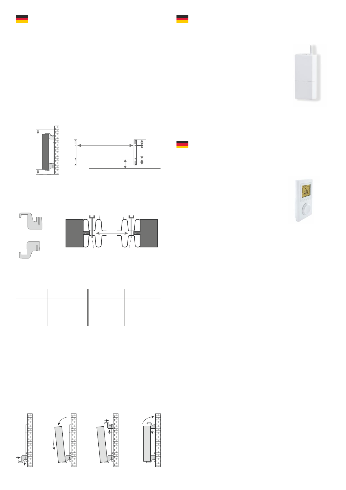
Schrauben und Dübel zu verwenden. Bitt e halten Sie bei der Ausrichtung der
Wandhalterung und des Heizgeräts immer die vorgegebenen Mindestabstände
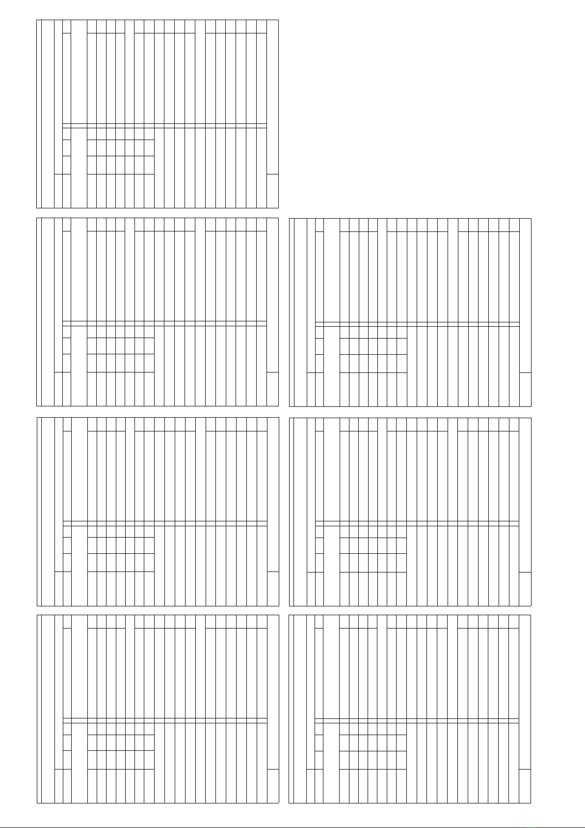
ein (siehe folgende Abbildungen).
Alle Heizgeräte besitzen vier temperaturbeständige Halter, die eine optimale
Fixierung des Heizgeräts gewährleisten.
Beachten Sie bitte die richtige Einhängeposition der oberen (Markierung 1)
und unteren (Markierung 2) Halter am Heizgerät (siehe folgende Abbildungen).
Mit der typenspezifischen Maßtabelle erhalten Sie stets die richtige
Positionierung für die U-Schienen und die Halter zum korrekten Einhängen und
Fixieren des Heizgeräts.
Zur Montage führen Sie bitt e die folgenden Schritt e durch:
1. Die beiden U-Schienen sind unter Einhaltung der Mindestabstände und je
nach typenspezifischem X/Y-Maß an der Wand zu befestigen.
2. Die beiden mit Markierung 2 gekennzeichneten Halter sind unten in die
U-Schienen einzusetzen.
3. Im Anschluss wird das Heizgerät in die unteren Halter eingehängt und schräg
nach vorne geklappt. Dabei das Heizgerät festhalten!
4. Die beiden mit Markierung 1 gekennzeichneten Halter sind oben in die
U-Schienen einzusetzen und vorübergehend hochzuziehen.
5. Abschließend das Heizgerät (ohne die Abdeckung) in eine senkrechte Position
aufrichten und die oberen Halter nach unten drücken, bis das Heizgerät
vollständig fixiert ist.
Anleitung Montage Wandhalterung Anleitung Funkthermostat (Empfänger)
Anleitung Funkthermostat (Sender)
Abb. 2
10 cm
8 cm
Maß X
Maß Y
190 mm
90 mm
90 mm
Abb. 1
Anbaumaße
X
1
2
oben
unten
Lamelle Lamelle
Einhängeteil Einhängeteil
Heizkörper-Typ Maß X Maß Y
in mm in mm
MINI 650 232 405
COMPACT 1300 466 405
MIDI 1950 766 405
Heizkörper-Typ Maß X Maß Y
in mm in mm
MAXI 2450 1066 405
SLIM 1200 766 120
SLIM 1600 1066 120
SLIM TALL 1600 232 1040
1
22
1
2
1
2
2
1
2
1
2
2
1
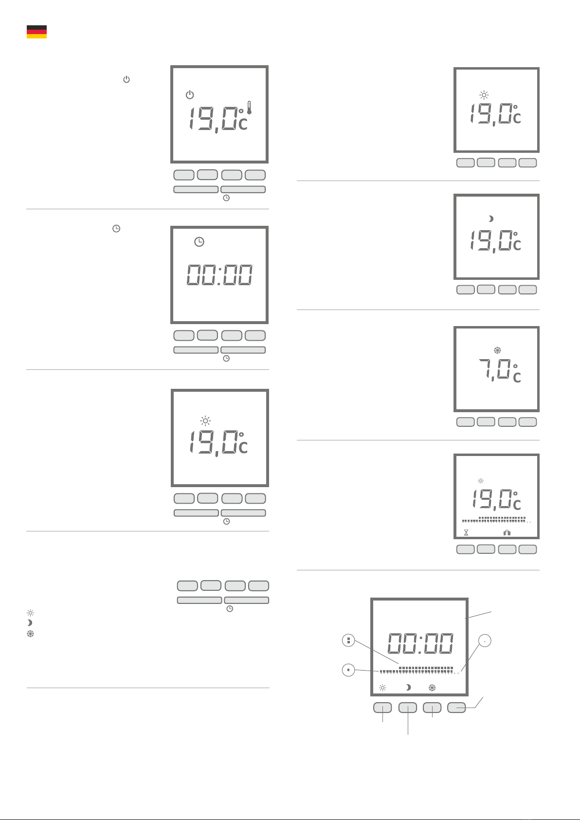
Wenn sich das Gerät in der Betriebsart AUS
befindet, ist folgendes Symbol im Display
sichtbar.
4.1.1 Komfort Dauerbetrieb
Das Gerät sorgt permanent für die eingestellte
Temperatur.
Die Temperatur lässt sich an der Taste + oder – in
Stufen von 0,5°C (von +5 bis +30°C) einstellen.
4.1.2 Nachtabsenkung Dauerbetrieb
Die gewünschte Absenkung lässt sich im Konfigu-
rationsmenü 1 regeln. Das Gerät sorgt permanent
für die eingestellte Temperatur.
Die Temperatur lässt sich an der Taste + oder – in
Stufen von 0,5°C (von +5 bis +30°C) einstellen.
Lässt sich dieser Wert nicht ändern, muss im
Konfigurationmenü 1 wie unter 6.1 beschrieben
„----“ eingestellt werden.
4.1.3 Frostschutz permanent
Das Gerät sorgt in dieser Betriebsart permanent
für die eingestellte Temperatur.
Die Temperatur lässt sich an der Taste + oder – in
Stufen von 0,5°C (von +5 bis +30°C) einstellen.
4.1.4 AUTO Programmierung
In dieser Betriebsart ist das Gerät gemäß der ein-
gestellten Programmierung automatikgesteuert.
Die aktuelle Stunde mit ihrer Einstellung Komfort,
Nachtabsenkung oder Frostschutz blinkt im Dis-
play.
In der Betriebsart AUS Taste drücken.
Die Tagesanzeige blinkt.
Wählen Sie den gewünschten Tag mit der
Taste + oder – aus. Mit OK bestätigen, dann
die Stunde und danach die Minuten einstel-
len. Zum Verlassen des Einstellmodus die
Taste Ein-Aus drücken.
Hinweis:
1 = Montag 5 = Freitag
2 = Dienstag 6 = Samstag
3 = Mittwoch 7 = Sonntag
4 = Donnerstag
Bei erster Inbetriebnahme wird für jeden Tag
das Programm KOMFORT von 8.00 – 22.00
Uhr und NACHTABSENKUNG von 22.00 – 8.00
Uhr verwendet.
Das Symbol ON in der Anzeige weist darauf
hin, dass das Gerät heizt.
Durch Drücken der Taste i können Sie die
Raumtemperatur oder die eingestellte
Temperatur anzeigen lassen. (Einstellungen
können Sie im Konfigurationsmenü 6.4
vornehmen.)
Die Taste Betriebsart wird erst aktiv, wenn das Gerät über die Taste Ein-Aus
eingeschaltet wurde.
Die verschiedenen Betriebsarten werden
mit der Taste BETRIEBSART ausgewählt.
KOMFORT
NACHT
FROSTSCHUTZ
AUTO mit Programmierung
Anmerkung – Ausrichtung Temperatursensor
Der Temperatursensor ist unten am Heizkörper in einem Klipp befestigt. Sollte
sich aufgrund einer Anbringung des Gerätes in einer Nische oder Ecke Beein-
flussungen auf die Raumtemperatur und gemessener Temperatur ergeben,
kann er aus diesem herausgenommen werden. Durch Drehen des Anschluss-
kabels des Sensors kann der Abstand zum Heizkörper erhöht werden. Alternativ
können die Einstellungen des Menüpunktes 2 vorgenommen werden.
Anleitung Displayregler
PROG
Ein-Aus Betriebsart
1. Ansicht im Betriebsmodus AUS
2. Uhrzeit einstellen
OK
1
2
3
4
5
6
7
►
+-
Ein-Aus Betriebsart
➘
3. Erste Inbetriebnahme
Ein-Aus Betriebsart
i+-
ON
4. Bedienung und Wahl der Betriebsart
Ein-Aus Betriebsart
AUTO
➘
i+-
4.1 Erklärung Betriebsarten
i+-
i+-
1
2
3
4
5
6
7
►
Oh 2 4 6 8 10 12 14 16 18 20 22 24
AUTO
PROG i
OK
1
2
3
4
5
6
7
►
Wochentag
PROG
Oh 2 4 6 8 10 12 14 16 18 20 22 24
Drücken für
1 Std. „Frostschutz“
Drücken für
1 Std. „Komfort“
Bestätigung und
weiter zur Ände-
rung/Einstellung
des nächsten
Tages
Drücken für
1 Std. „Nachtabsenkung“
ein Balken =
„Nachtabsenkung“
zwei Balken =
„Komfort“ kein Balken =
„Frostschutz“
5. Einstelldisplay AUTO-Programmierung ändern

Anleitung Displayregler
6. Konfigurationsmenü
PROG
Ein-Aus Betriebsart
10 sec.
➘
Im Konfigurationsmenü können Sie folgende
Einstellungen vornehmen:
- Einstellwert Nachtabsenkung regeln
- Korrektur der gemessenen Temperatur
- Dauer der Hintergrundbeleuchtung
- Wahl der Temperaturanzeige in der
Betriebsart AUTO
- Fenster Offen-Erkennung de-/aktivieren
- Adaptives Startverhalten de-/aktivieren
- Produktnummer aufrufen
Konfigurationsmenü aufrufen
In der Betriebsart AUS öffnen Sie das erste
Konfigurationsmenu, indem Sie den Ein-Aus-
Schalter 10 Sekunden lang drücken.
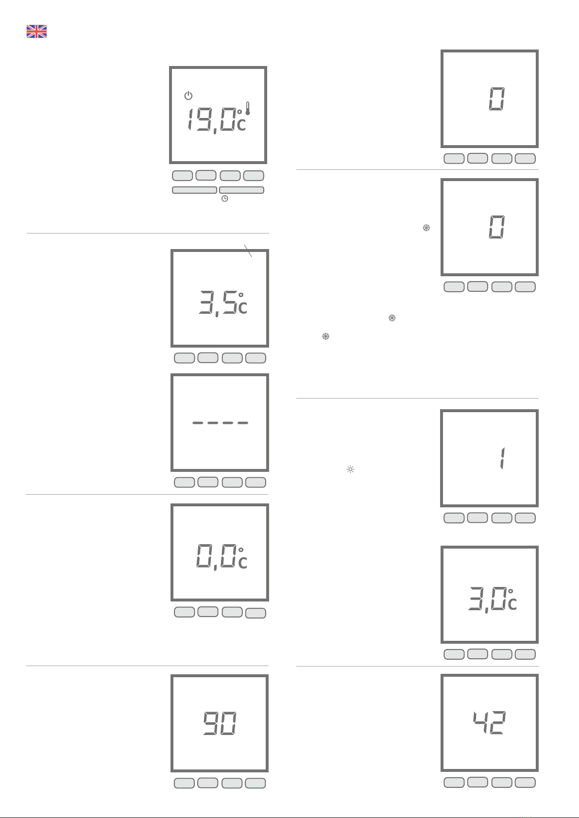
Menü 4
6.4 Wahl der Temperaturanzeige in der
Betriebsart AUTO (Programmierung)
0 = Ständige Anzeige der Raumtemperatur.
1 = Ständige Anzeige der eingestellten
Temperatur.
Ändern mit der Taste + oder -. Danach mit
der Taste OK bestätigen.
Menü 5
6.5 Fenster Offen-Erkennung
Die Erkennung eines offenen Fensters erfolgt
bei schneller Temperatursenkung. In diesem
Fall blinkt auf der Anzeige und die Frost-
schutz-Solltemperatur wird angezeigt.
0 = Erkennung offenes Fenster deaktiviert
1 = Erkennung offenes Fenster aktiviert
Ändern mit der Taste + oder -. Danach mit der
Taste OK bestätigen.
Wird ein offenes Fenster erkannt (* blinkt)
kann durch drücken auf * diese Funktion
vorübergehend deaktiviert werden.
Wird das Fenster wieder geschlossen, kann es
einige Minuten dauern, bis der Heizkörper
weiter heizt.
Bitte beachten: Ein offenes Fenster wird im
AUS-Betrieb nicht erkannt.
Menü 6
6.6 Adaptive Regelung des Heizbeginns
Dank dieser Funktion kann die gewünschte
Temperatur zum gewünschten Zeitpunkt
erreicht werden. Bei aktivierter adaptiven
Regelung blinkt auf der Anzeige.
0 = Adaptive Regelung deaktiviert
1 = Adaptive Regelung aktiviert
Ändern mit der Taste + oder -. Danach mit der
Taste OK bestätigen.
Regelung der Temperatur-Zeit-Kurve (bei
aktivierter adaptiven Regelung)
Von 1°C bis 6°C, in Stufen von 0.5°C.
Wird die Soll-Temperatur zu schnell erreicht,
sollte ein niedrigerer Wert eingestellt wer-
den.
Wird die Soll-Temperatur zu langsam erreicht,
sollte ein höherer Wert eingestellt werden.
Menü verlassen
6.7 Produktnummer
Mit diesem Menü lässt sich die Produktnum-
mer anzeigen. Zum Verlassen des Konfigura-
tionsmodus drücken Sie die OK-Taste.
Vergessen Sie die Produktnummer mit OK zu
bestätigen, werden Ihre Änderungen nicht
gespeichert und nicht angewendet.
Menü 1
6.1 Einstellwert Nachtabsenkung regeln
Standardwert Nachtabsenkung = Tempera-
turwert KOMFORT abzüglich 3,5°C. Diese
Absenkung lässt sich in 0,5°C -Stufen von 0 bis
10°C ändern.
Ändern mit der Taste + oder -. Danach mit der
Taste OK bestätigen.
Um die Änderung des Einstellwerts durch den
Benutzer zu autorisieren, drücken Sie die
Taste + solange, bis in der Anzeige „----“ er-
scheint.
Siehe 4.1.2 Nachtabsenkung Dauerbetrieb
Menü 2
6.2 Korrektur der gemessenen Temperatur
Weicht Ihre Raumtemperatur von der am
Gerät gemessenen und angezeigten Tempe-
ratur ab, nutzen Sie Menü 2. Hier lässt sich
für den Messfühler ein Ausgleichswert von
-5°C bis +5°C einstellen (in Stufen von 0,1°C ).
Zeigt der Displayregler eine zu niedrige Tem-
peratur an, erhöhen Sie den Ausgleichswert.
Beispiel: • Raumtemperatur = 21°C
• angezeigte Temp. = 20°C
• Stellen Sie +1,0°C in Menü 2 ein.
Ändern mit der Taste + oder -. Danach mit der
Taste OK bestätigen.
Menü 3
6.3 Dauer der Hintergrundbeleuchtung
Die Beleuchtungsdauer kann in Stufen von 15
Sekunden zwischen 0 und 225 Sekunden
eingestellt werden.
Der Standardwert ist 90 Sekunden.
Ändern mit der Taste + oder -. Danach mit der
Taste OK bestätigen.
1
1
2
2
3
3
4
4
5
5
6
6
7
7
►
►
Nr. des Menüs
OK
OK
+
+
-
-
1
2
3
4
5
6
7
►
OK+-
➘
1
2
3
4
5
6
7
►
OK
+-
1
2
3
4
5
6
7
►
OK+-
1
2
3
4
5
6
7
►
OK+-
1
1
2
2
3
3
4
4
5
5
6
6
7
7
►
►
OK
OK
OK
+
+
-
-
Anleitung Displayregler
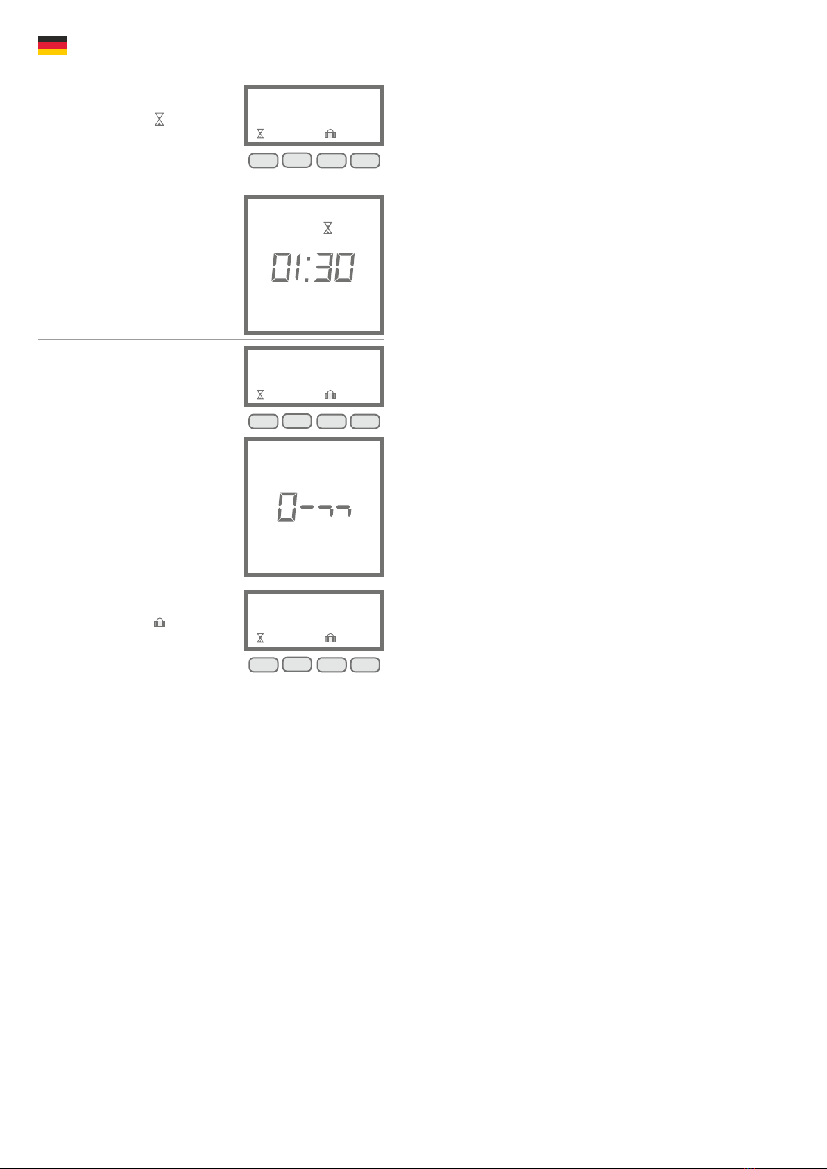
7.1 Zeitbefristete Temperatureinstellung
Durch Drücken der Taste kann ein Tem-
peraturwert für eine bestimmte Zeitdauer
eingestellt werden.
Stellen Sie die gewünschte Temperatur (+5°C
bis +30°C) an der Taste + oder - ein. Danach
mit OK bestätigen und die Zeitdauer ein-
stellen.
Stellen Sie die gewünschte Zeitdauer (von 30
Minuten bis 72 Stunden) an der Taste + oder -
ein (z.B. 1h30) und bestätigen Sie mit OK.
Zum Löschen der befristeten Temperatur-
einstellung drücken Sie die Taste OK erneut.
7.2 Kindersicherung
Die Tastatur lässt sich sperren, indem die
zwei Tasten mittig 5 Sekunden lang gleich-
zeitig gedrückt werden. In der Anzeige er-
scheint kurz ein „Schlüssel".
Zum Entriegeln drücken Sie erneut gleich-
zeitig die Tasten + und -.
7.3 Abwesenheitsfunktion
Durch Drücken der Taste können Sie Ihr
Gerät für die Dauer von 1 bis 365 Tage auf
Frostschutz einstellen.
Die Anzahl der Tage Ihrer Abwesenheit stellen
Sie an der Taste + oder - ein und bestätigen
mit OK. Zum Löschen des Abwesen-
heitsbetriebs drücken Sie die Taste OK
erneut.
7. Weitere Einstellungen
➘
PROG
OK
➘
PROG
➘
➘
PROG

7. Cleaning of device
Switch the radiator off before each cleaning sequence and allow it completely
cool down. Only wipe the radiator off with a soft, damp cloth and do not use any
chemical detergents or abrasive milk. A correspondingly designed cleaning brush
can be used for the cleaning of the slats (not included). We offer you an
appropriate product in our online shop for purchase in the accessories section.
8. Directions for disposal
Disposal of old equipment in Germany
The devices marked with the symbol below must not be
disposed of with household waste. As a manufacturer, we
are responsible for the environmentally sound treatment
and recycling of WEEE as part of our production responsibility. Please contact
your local authority for further information on collection and disposal.
Disposal outside of Germany
Dispose of these appliances in an expert and proper manner in accordance
with local legislation and regulations.
9. Guarantee conditions
For this product, we provide a 30-year warranty on the area of heat generation
and usability of the basic unit as well as a 2-year warranty on the control
technology, the spare parts and the accessories.
In other respects that statutory warranty shall apply. Our warranty conditions
regulate the additional warranty claims, which are in addition to the statutory
warranty claims of the customer.
The warranty conditions apply only to devices which are purchased by the end
user as new devices. A guarantee obligation does not come about insofar as the
final customer purchases a used device or for its part a new device from another
end customer.
The warranty is provided if a manufacturing and/or material fault occurs during
the warranty period on our radiators and the accessories.
Within the warranty period that commences upon the delivery date, we will
remedy free of charge any malfunctions that are demonstrably due to a material
defect or defective performance.
Our guarantee includes the free exchange of defective parts as well as the
provision of free spare parts during the warranty period.
We are only liable if the function of the radiator is impaired and the defect is not
caused by negligent, intentional or improper handling, use of force, transport,
misuse, connection to incorrect mains voltages, failure to observe the
appropriate operating instructions or installation instructions, improper
cleaning or corrosion damage due to caustic water, by chemical and / or
electrochemical effects or by normal wear and tear.
The warranty will become void if the unit has been subjected to interventions or
attempted repairs by persons who have not been authorised to do so by us.
Please note that dismantling of the heater by the customer or third parties is
fundamentally not permissible. If there is a violation this warranty entitlement
shall cease to apply.
The possible replacement of the radiator side part (e.g. when changing the
control technology) and / or the possible shortening of the connecting cable (e.g.
removal of the earthed plug for the purpose of producing a fixed connection)
does not lead to a loss of warranty, insofar as no intervention in or manipulation
of electronic components takes place, beyond the necessary extent of the
modification to be performed, and the correspondingly permissible work is
performed by a qualified expert.
The warranty covers the careful inspection of the radiator or the accessories
whereby it must be initially determined whether a warranty claim applies. In the
event of a claim under the warranty we solely decide in which manner the fault
shall be rectified. We are at liberty to replace a radiator or accessory or to
perform a repair. During the warranty period, we assume all material, assembly
and transport costs within the scope of this warranty.
In addition to the above-mentioned warranty service, the end customer cannot
assert any claims for indirect damage or consequential damage caused by the
device, in particular for compensation for damages incurred outside the device.
Statutory claims of the customer against us shall remain unaffected by this
clause. Warranty claims must be reported to us before expiry of the warranty
period, within one week of the defect being detected. For this purpose, please
use the „Warranty Certificate“ attached to this manual and, after having filled it
in, send it to us by post to the stated address or an electronic form by e-mail to
our e-mail address mentioned above.
General Information
1. Safety instructions
Please read the user manual of your new AeroFlow® electronic radiator and the
information listed here carefully. Store these instructions in a safe place and pass
them on to the following user/owner if necessary. The electronic heating you
have just purchased is only suitable for heating inside enclosed rooms. Damaged
devices (e.g. damaged connecting cables) must not be operated.
Our radiators are tested according to the applicable IP protection class when
properly installed (International Protection Code – in this case: Protected against
spray water). In the fixed electrical installation, a separating device with at least a
3mm contact opening shall be provided on each pole (for example, a safety
device, residual current circuit breaker). Substances which are prone to ignition
or thermal decomposition (e.g., adhesives of floor coverings) may only be used if
it is certain the heater has been cooled to room temperature. The heater must
not be placed directly below a wall socket.
The radiator is not intended to be used by persons (including children) with
limited perceptual abilities or by people with lack of experience and / or lack of
knowledge of using it. Unless they are supervised by a person responsible for
their safety or have received instructions from this person on how to use the
radiator. Children should be supervised to ensure that they do not play with the
radiator.
2. Electrical connection
Your AeroFlow® electric radiator system is suitable for fixed connection to wall
sockets or operation from power sockets. An electrician must be consulted
when installing it via a wall socket. If the mains connection cable of the radiator is
damaged, it needs to be replaced by us or a suitably qualified electrician in order
to prevent danger and additional damage.
The radiator may only be operated with a thermostat directly on the radiator or
with an external control. The heating control must always be performed using a
suitable room thermostat.
3. Installation
Our devices are mounted horizontally on the wall. Attachment to the ceiling is
not permitted. The radiator should normally be installed under a window or on
an external wall. Please ensure that the radiator can radiate into the room as
freely as possible. You can find our detailed installation information on Page 7.
4. Heating
The radiator is controlled via the externally or internally installed room
thermostat. A higher setting means a longer operating time on the radiator.
Please refer to the operating instructions of the room thermostat on the
following pages. It is possible that a slight odour can develop during initial
commissioning, since some materials still have to be baked out. This does not
pose any threat, and it will run off completely after a period of time. Please
ventilate the rooms well if necessary. In rare cases, noise can occur in the form of
cracking, which is caused by heat-induced material movements, which are
harmless.
5. Overheating protection
For your safety, the heater is equipped with a temperature switch integrated in
the heating system. If the radiator is not heated in the permitted manner (e.g. by
covering or blocking) the radiator switches off automatically. The covering of the
heater (e.g. through towels) during operation is not permissible, it is a fire
hazard! Any resulting defects on a temperature switch and the resulting costs for
the repair shall be borne exclusively by the party causing the damage. We can
offer you a towel rack suitable for our radiators in our online shop.
6. Malfunctions
If the radiator does not emit any heat, please check that the thermostat is pre-
set to the desired temperature. In addition, it is essential to check that the local
power distribution is switched on or that the fuse is in working order. If you
encounter such malfunctions, please contact your installer. In the event of a
complaint being addressed to us, the serial number of the device is required for
order processing. You will find this information on the rating plate.
Manual on assembly of wall bracket Manual wireless thermostat (receiver)
Manual wireless thermostat
(transmitter)
Operating of a domotics transmitter
Press the button on the receiver for more than 3 seconds until the indicator light
starts to flash.
Two operating modes are possible:
1. Slow flashing: On/off switch
2.Quick flashing: Pulse generator
Switching of the modes
Briefly press the button on the receiver. Set the transmitter
to the configuration mode. Check that the indicator
light on the receiver is not flashing.
Deleting assignment
To delete all assigned products, press the button of the receiver for approx. 30
seconds until the indicator light flashes briefly. All transmitters are now deleted.
For detailed information about the wireless transmitter, please refer to the
attached description in the wireless thermostat itself.
Operation
Bidirectional wireless protocol on wireless frequency 868 MHz. The range
amounts to 100 to 300 metres (if there are no obstacles). Placement on the wall
or mobile in the room.
Settings
Encoder for on/off and basic settings
Setting buttons + / - with programmable settings for:
- Daily/weekly programming
- Detection of open windows
- Presence detector (with additional motion detector)
- Room temperature control with display screen
- Acoustic signal when switching on / off
- Display of the ambient temperature
- Display of the power consumption (kWh) of the assigned electric heaters
- Holiday program
- Winter time
For detailed information about the wireless transmitter settings, please refer to
the attached description of the wireless thermostat itself.
Window open detection
Radiators with X3D receivers must be equipped with a temporary radiator
shutdown function to comply with EU Directive 2009/125/EG. To ensure this,
you can purchase wireless opening detectors "DO BL Tyxal+" (Part No. 6412288)
or "MDO BL Tyxal+" (Part No. 6412305) from DELTA DORE . Instructions are
included with the detector. Unfortunately, since we do not have these items in
our program, we are unable to provide assistance for setting them up.
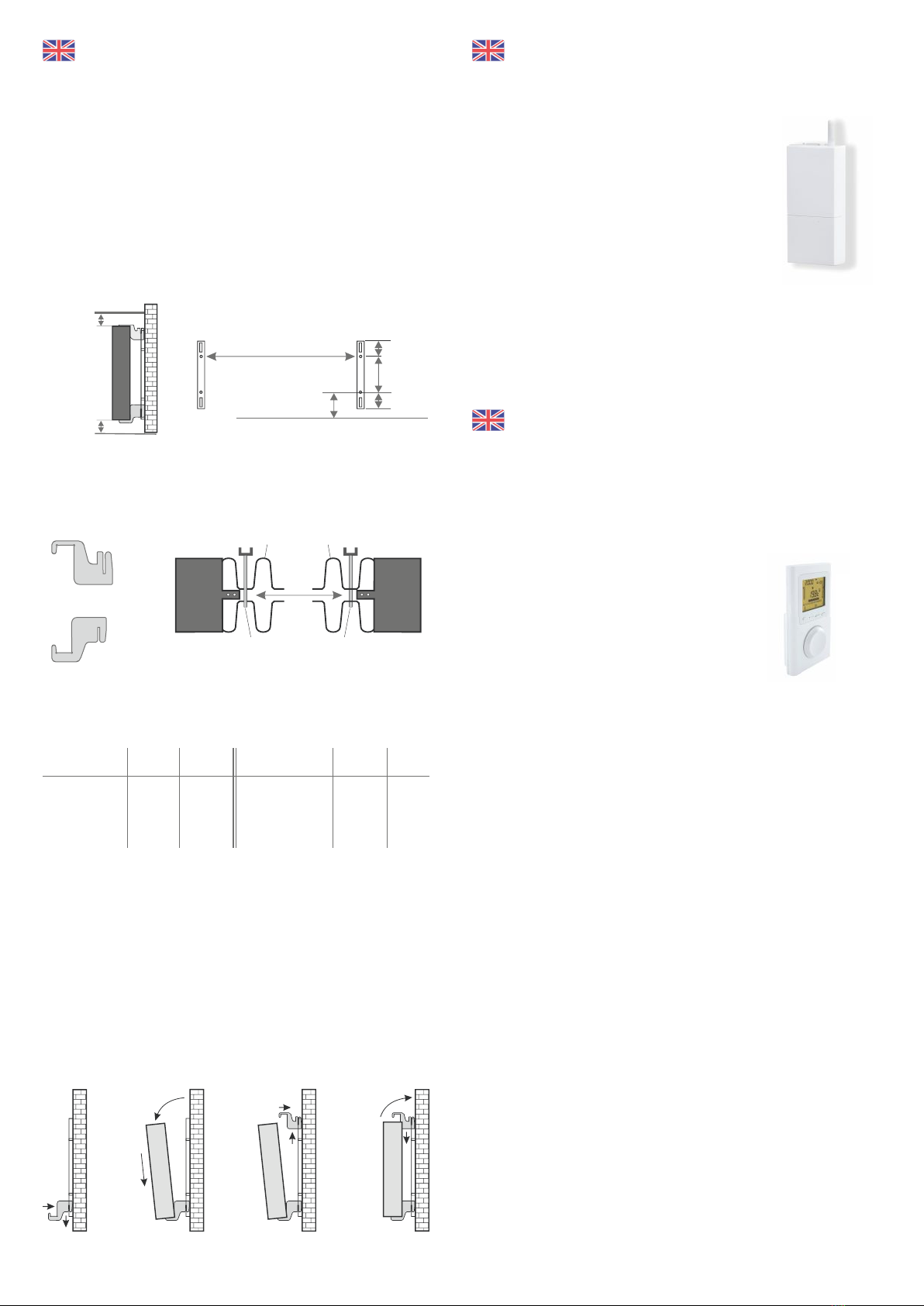
Only the wall bracket supplied may be used for wall mounting! The latest
regulations according to VDE 0100 part 701 must be complied with for the
installation and operation in damp rooms.
The device may not be mounted directly under a wall socket. In order to avoid
excessive heat radiation upon the wall socket, a certain safety distance must also
be taken into account between the radiator and the wall socket. This distance is
largely determined by the material quality and heat resistance of the locally
installed socket and therefore can not be assessed by us. We assume no liability
for improper handling and possible damages resulting from this. In case of
doubt, consult a specialist before installation. Suitable screws and dowels must
be used depending on the type and condition of the wall material. When
positioning the wall bracket and the heater, please always observe the stipulated
minimum distances (see the following figures).
All radiators have four temperature-resistant holders, which guarantee optimum
fixing of the heater. Please note the correct hanging position of the upper
(marking 1) and lower (marking 2) holders on the heater (see following figures).
With the type-specific dimension table, you always obtain the correct
positioning for the U-rails and the holders for the correct mounting and fixing of
the radiator.
For the assembly please perform the following steps:
1. The two U-rails must be fixed to the wall whilst observing the minimum
distances and depending on the type-specific X / Y-dimension.
2. The two holders marked with the marking 2 are to be inserted into the U-rails
at the bottom.
3. Following this the radiator is hooked into the lower holders and tilted forward
at an angle. Hold the radiator while doing so!
4. The two holders marked with the marking 1 are to be inserted into the U-rails
at the top and temporarily pulled up.
5. Finally, place the radiator in a vertical position and press the upper holders
down until the heater is completely fixed in place.
Fig. 2
10 cm
8 cm
Dim X
Dim Y
190 mm
90 mm
90 mm
Fig. 1
Aachment dimensions
X
1
2
Above
Below
Slat Slat
holder holder
Radiator type Dim X Dim Y
in mm in mm
MINI 650 232 405
COMPACT 1300 466 405
MIDI 1950 766 405
Radiator type Dim X Dim Y
in mm in mm
MAXI 2450 1066 405
SLIM 1200 766 120
SLIM 1600 1066 120
SLIM TALL 1600 232 1040
1
22
1
2
1
2
2
1
2
1
2
2
1

When the device is in the OFF operating
mode, the following symbol appears in
the display.
4.1.1 Comfort permanent mode
The device permanently ensures the set tempe-
rature.
The temperature can be adjusted by pressing the
+ or – button in steps of 0.5°C (from + 5 to + 30°C).
4.1.2 Nighttime lowering permanent operation
The desired lowering can be regulated in the con-
figuration menu 1. The device permanently ensu-
res the adjusted temperature.
The temperature can be adjusted by pressing the
+ or – button in steps of 0.5°C (from + 5 to + 30°C).
If you can‘t change this value, set configuration
menu 1 to "----": Refer to 6.1 in this manual.
4.1.3 Permanent frost protection
The device permanently ensures the set tempe-
rature in this mode.
The temperature can be adjusted by pressing
the + or – button in steps of 0.5°C (from + 5 to +
15°C).
4.1.4 AUTO Programming
In this operating mode, the device is automatically
controlled according to the set programming. The
current hour with its comfort, night-time lowering
or frost protection setting flashes in the display.
Press the button in the operating mode
OFF.
The date display flashes.
Select the desired day with + or – button.
Confirm with OK, then set the hour and
after that the minutes. To exit the setting
mode press the ON-OFF key.
Notice:
1 = Monday 5 = Friday
2 = Tuesday 6 = Saturday
3 = Wednesday 7 = Sunday
4 = Thursday
During inital operation the COMFORT pro-
gram is used every day from 8:00 am until
10:00 pm and NIGHT REDUCTION from
10:00 pm until 8:00 am.
The ON symbol in the display indicates that
the device is heating.
By pressing the i button you can display the
room temperature or the set temperature.
(You can define the following settings in the
configuration menu 6.4.)
Manual for display controller
PROG
On-Off Mode
1. View in operating mode OFF
2. Setting the time
OK
1
2
3
4
5
6
7
+-
On-Off Mode
➘
3. First commissioning
On-Off Mode
i+-
ON
4. Operation and selection of the operating mode
On-Off Mode
AUTO
➘
i+-
4.1 Explanation of operating modes
i+-
i+-
1
2
3
4
5
6
7
Oh 2 4 6 8 10 12 14 16 18 20 22 24
AUTO
PROG i
OK
1
2
3
4
5
6
7
Day
PROG
Oh 2 4 6 8 10 12 14 16 18 20 22 24
One bar =
„Nighttime lowering“
Two bars =
„Comfort“ No bar =
„Frost protection“
5. Setting display change AUTO programming
►
►
►
The operating mode button is not activated until the device has been switched
on using the On-Off button.
The various modes are selected with the
MODE button.
COMFORT
NIGHT
FROST PROTECTION
AUTO with programming
Note – alignment of the temperature sensor
The temperature sensor is attached to the bottom of the radiator in a clip. If, due
to an placement of the device in a niche or corner, the room temperature and
the measured temperature is influenced, it can be removed from it. The distance
to the radiator can be increased by turning the connection cable of the sensor.
Alternatively, the settings of menu item 2 can be performed.
Press for
1 hour „Frost protection“
Press for
1 hour „Comfort“
Confirmation
and Continue to
change / setting
of the next day
Press for
1 hour „Nighttime lowering“
Manual for display controller
6. Configuration menu
PROG
On-Off Mode
➘
1
2
3
4
5
6
7
menu number
OK+-
1
2
3
4
5
6
7
OK+-
➘
1
2
3
4
5
6
7
OK
+-
1
2
3
4
5
6
7
OK+-
1
1
2
2
3
3
4
4
5
5
6
6
7
7
OK
OK
+
+
-
-
OK
►
►
►
►
►
►
You can define the following settings in the
configuration menu:
- Regulate the setting value for nighttime
lowering
- Correction of the measured temperature
- Duration of the background lighting
- Selection of the temperature display in the
AUTO mode
- de-/active window open detection
- de-/active adaptive start control
- Call up the product number
Call up the configuration menu
In the OFF mode you open the first confi-
guration menu by pressing the On-Off-switch
for 10 seconds.
Menu 4
6.4 Selection of the temperature display in
the AUTO mode (programming)
0 = permanent display of the room tempera
ture.
1 = permanent display of the set tempera-
ture.
Change with the button + or –. Following this
confirm with the OK button.
Menu 5
6.5 Open Window detection
The detection of an open window occurs
when the room temperature falls rapidly.
In this case, the display shows a flashing
pictogram, as well as the frost protection
set-point temperature.
0 = Open window detection is deactivated
1 = Open window detection is activated
Change with the button + or –. Following this
confirm with the OK button.
If a open window is detected ( flashes) you
can deactivate this function temporarily by
pressing .
When the window is closed again, it may take
a few minutes for the radiator to continue
heating.
Please note: an open window cannot be
detected in OFF-Mode.
Menu 6
6.6 Adaptive start control
This feature enables to reach the set-point
temperature at a set time.
When this feature is activated, the display
shows a flashing .
0 = Adaptive start control deactivated
1 = Adaptive start control activated
Change with the button + or –. Following this
confirm with the OK button.
Adjusting the time-temperature-slope
(when adaptive start control is activated)
From 1°C to 6°C, in steps of 0.5°C.
If the set-point temperature is reached too
early, then a lower value should be set.
If the set-point temperature is reached too
late, then a higher value should be set.
Menu exit
6.7 Product number
The product number can be displayed with
this menu. To exit the configuration mode
press the OK key.
Menu 1
6.1 Regulate the setting value for nighttime
lowering
Default value Nighttime lowering = Tempe-
rature value of COMFORT minus 3.5°C. This
lowering can be changed in graduations of
0.5°C from 0 to 10°C. Change with the button
+ or –. Confirm with the OK button.
Press the button + until "----" appears in the
display to authorise the change of the value
by the user.
Refer to 4.1.2 Nighttime lowering perma-
nent operation
Menu 2
6.2 Correction of the measured temperature
If the room temperature deviates from the
temperature measured on the radiator (
displayed on the device), use Menu 2. A
compensation value for the measuring sensor
from - 5°C to + 5°C can be entered here (in
steps of 0.1°C).
Example: • room temperature = 21°C
• measured temp. = 20°C
• Set +1,0°C in Menu 2.
Change with the button + or –. Following this
confirm with the OK button.
Menu 3
6.3 Duration of the background lighting
The duration of the lighting can be set in
steops of 15 seconds between 0 and 225 se-
conds.
The default value is 90 seconds.
Change with the button + or –.Following this
confirm with the OK button.
1
2
3
4
5
6
7
►
OK+-
1
2
3
4
5
6
7
►
OK+-

Manual for display controller
7. Further settings
➘
PROG
OK
7.2 Childlock
➘
PROG
➘
7.3 Absence function
➘
PROG
Menu 5
7.1 Time-limited temperature setting
A temperature value can be set for a certain
duration by pressing the button.
Select the desired temperature (+ 5°C to +
30°C) at the + or – button. Following this
confirm with the OK button and set the
duration.
Set the desired duration from 30 minutes to
72 hours) at the + or – button (e.g. 1h30) and
confirm with the OK button.
To delete the temporary temperature setting,
press the OK button again.
The keyboard can be locked by simulta-
neously pressing the two buttons in the
middle at the same time for 5 seconds. A
"Key" briefly appears in the display.
To unlock it press the + and – buttons si-
multaneously once more.
By pressing the button, you can set your
device to frost protection for a period of 1 to
365 days.
You can set the number of days of your ab-
sence by pressing the + or – key and confirm
by pressing OK.
To delete the absence mode, press the OK
button again.

Remarques générales
1. Consignes de sécurité
Veuillez lire attentivement le mode d‘emploi de votre nouveau chauffage
électrique AeroFlow®. Conservez-le précieusement et remettez-le au nouveau
propriétaire, le cas échéant. Votre nouveau chauffage électrique sert
uniquement à chauffer des espaces intérieurs clos. Un appareil défectueux (p.
ex. une conduite de raccordement endommagée) ne doit en aucun cas être
utilisé. S‘ils sont installés par du personnel qualifié, nos radiateurs à inertie sèche
sont contrôlés conformément aux indices de protection correspondants
(International Protection Code – ici: protégés contre les pulvérisations).
L‘installation électrique doit être équipée d‘un sectionneur avec au moins 3 mm
d‘ouverture de contact à chaque pôle (p. ex. un disjoncteur ou un disjoncteur
différentiel). Les matières inflammables ou susceptibles de subir une
décomposition thermique, comme la colle des revêtements de sol, peuvent
uniquement être utilisées après avoir vérifié que le radiateur est refroidi à
température ambiante. Le radiateur ne doit pas être installé sous une prise
électrique murale. Le radiateur n‘est pas destiné à être utilisé par des personnes
(y compris des enfants) dont les facultés de perception sont limitées, ou ne
disposant de l‘expérience et/ ou du savoir-faire nécessaire, à moins qu‘elles ne
soient surveillées par une personne responsable de leur sécurité ou qu‘elles
aient reçu de cette dernière des instructions d‘utilisation du radiateur. Les
enfants doivent être sous surveillance afin de s‘assurer qu‘ils ne jouent pas avec
le radiateur.
2. Raccordement électrique
Votre chauffage électrique AeroFlow® peut être utilisé avec un raccordement
mural fixe ou être branché à une prise de courant. Si vous choisissez de l‘installer
avec un raccordement mural, consultez obligatoirement un électricien. Si le
câble d‘alimentation secteur d‘un radiateur est défectueux, celui-ci doit être
remplacé par notre personnel ou par un électricien dûment qualifié afin d‘éviter
tout danger et autre dommage. Le radiateur ne peut être utilisé qu‘avec un
thermostat directement situé dessus ou une commande extérieure. Le réglage
du chauffage doit toujours être effectué au moyen d‘un thermostat ambiant
approprié.
3. Montage
Nos appareils sont montés au mur de manière horizontale. Il est interdit de les
fixer au plafond. En règle générale, il est préférable d‘installer le radiateur sous
une fenêtre ou sur un mur extérieur tout en veillant à ce que l‘espace soit
suffisant pour que le chauffage diffuse dans la pièce. Retrouvez nos instructions
détaillées en page 11.
4. Chauffage
Le thermostat ambiant externe ou interne régule le radiateur. Un paramétrage
élevé entraîne nécessairement une durée de fonctionnement prolongée du
radiateur. À ce sujet, lisez attentivement le mode d‘emploi des thermostats
ambiants aux pages suivantes. Lors de la première mise en service, des
matériaux doivent encore être chauffés. Il est donc possible qu‘une légère odeur
apparaisse, laquelle ne présente aucun danger et disparaîtra totalement
quelque temps après. Le cas échéant, aérez bien les pièces. Dans de rares cas,
des crépitements liés aux mouvements de matériaux entraînés par la chaleur
peuvent survenir. Ces bruits ne présentent aucun risque.
5. Protection contre la surchauffe
Pour votre sécurité, le radiateur est équipé d‘un commutateur de sécurité
intégré dans le chauffage. En cas d‘augmentation non autorisée de la
température du chauffage (p. ex. si le radiateur est recouvert ou si son espace est
encombré), le radiateur s‘éteint automatiquement. Il est interdit de recouvrir le
radiateur (p. ex. avec des serviettes) s‘il est en cours d‘utilisation. Risque
d‘incendie! Le responsable est seul tenu de prendre en charge les dommages
éventuels qui en résultent au niveau du commutateur de température ainsi que
les coûts afférents de réparation. Un porte-serviette adaptable à nos radiateurs
est proposé à l‘achat sur notre boutique en ligne.
6. Dysfonctionnements
Si le radiateur ne génère aucune chaleur, vérifiez si le préréglage du thermostat
est défini sur la température souhaitée. Il est également toujours utile de vérifier
que l‘alimentation électrique locale et le fusible fonctionnent. Si de tels
dysfonctionnements surviennent, consultez votre électricien. Si vous souhaitez
nous adresser une réclamation, transmettez le numéro de série de l‘appareil afin
que nous puissions traiter votre demande. Cette information se trouve sur
l‘étiquette de l‘appareil.
7. Nettoyage de l‘appareil
Avant de procéder au nettoyage, éteignez le radiateur et laissez-le refroidir.
Nettoyez le radiateur uniquement à l‘aide d‘un chiffon doux humide et n‘utilisez
ni produit de nettoyage chimique, ni détergent. Vous pouvez utiliser une brosse
de nettoyage spécifique pour nettoyer les ailettes. Elle n‘est pas incluse dans la
livraison, mais nous vous en proposons une sur notre boutique en ligne, dans la
catégorie Accessoires.
8. Instructions relatives à l‘élimination
Élimination des appareils usagés en Allemagne
Les appareils signalés par le symbole ci-contre ne doivent pas
être jetés avec les ordures ménagères. En tant que fabricant,
nous veillons au traitement et à la valorisation non polluants
des appareils usagers dans le cadre de la responsabilité de production. Ren-
seignez-vous auprès de votre commune pour obtenir des informations sur la
collecte et l‘élimination.
Élimination à l‘extérieur de l‘Allemagne
Éliminez ces appareils conformément à la réglementation et à la législation en
vigueur.
9. Conditions de garantie
Ce produit dispose d‘une garantie de fonctionnement de 30 ans dans le domaine
de la production de chaleur et de l‘utilisation de l‘appareil de base, ainsi que
d‘une garantie de 2 ans sur la technique de régulation, les pièces détachées et les
accessoires. La garantie légale s‘applique également. Nos conditions de garantie
réglementent les prestations de garantie supplémentaires applicables en plus
des droits de garantie légaux du client. Les conditions de garantie sont
uniquement applicables pour les appareils que le consommateur achète neufs.
L‘obligation de garantie n‘est pas applicable si le consommateur acquiert un
appareil déjà utilisé ou un appareil neuf auprès d‘un autre consommateur. La
garantie intervient uniquement en cas de survenue d‘un défaut de matériel et/
ou de fabrication sur nos radiateurs et leurs accessoires pendant la période de
garantie. Au cours de la période de garantie, dont le jour de livraison marque le
commencement, nous procédons au dépannage gratuit de tous les défauts de
fonctionnement qui surviennent et qui sont manifestement liés à un défaut
matériel ou à une qualité moindre. Notre garantie prévoit le remplacement
gratuit des pièces défectueuses ainsi que la gratuité des pièces détachées au
cours de la période en vigueur.
Nous engageons uniquement notre responsabilité si le fonctionnement du
radiateur est altéré et que le défaut ne soit pas lié à une manipulation
imprudente, intentionnelle ou incorrecte, à l‘usage de la violence, au transport, à
une mauvaise utilisation, au raccordement à une mauvaise tension de secteur,
au non-respect des consignes de montage et d‘utilisation, à un mauvais
nettoyage ou à des dommages dus à la corrosion liée à l‘utilisation d‘eau
agressive, à des dommages résultant d‘actions chimiques et/ou électro-
chimiques ou à l‘usure normale.
La garantie est annulée en cas de modifications ou de tentatives de réparation
effectuées par des personnes non autorisées. Veuillez noter que le démontage
du radiateur par le client ou par un tiers est interdit. En cas de violation de cette
règle, la garantie devient caduque.
La garantie est conservée en cas d‘éventuel échange de la pièce latérale
modulaire du radiateur (p. ex. en cas de modification de la technique de régula-
tion) et/ou de l‘éventuel raccourcissement du câble d‘alimentation (p. ex. en cas
de retrait de la prise Schuko pour réalisation d‘un raccordement fixe), à
condition, au-delà des modifications nécessaires à apporter, que ces actes ne
donnent lieu à aucune modification ou manipulation des éléments
électroniques et que les travaux autorisés soient réalisés par un professionnel
qualifié.
La prestation de garantie comprend l‘examen minutieux du radiateur ou de
l‘accessoire après lequel il sera décidé de l‘exécution ou non de la garantie. En cas
de garantie, nous sommes seuls décisionnaires de la manière dont le défaut sera
corrigé. Nous sommes libres d‘échanger un radiateur ou une pièce d‘accessoire
ou de procéder à une réparation. Dans le cadre de l‘étendue de la garantie, et au
cours de cette dernière, nous prenons en charge l‘ensemble des coûts relatifs au
matériel, au montage et au transport.
Pendant la prestation de garantie autorisée susmentionnée, le consommateur
ne peut invoquer, dans le cadre de cette garantie, aucun droit relatif à des
dommages indirects ou consécutifs causés par l‘appareil, notamment de
remplacement des dommages non causés par l‘appareil. Les droits légaux du
client à notre encontre ne sont pas remis en cause. Les demandes en garantie
doivent nous être adressées avant l‘expiration de celle-ci, dans la semaine qui
suit la découverte du défaut. Pour ce faire, veuillez utiliser le bordereau de
garantie joint à ce mode d‘emploi et veuillez nous le retourner rempli par voie
postale à l‘adresse indiquée, ou par e-mail sous forme de formulaire
électronique à l‘adresse e-mail indiquée.
Instructions de montage du
support mural
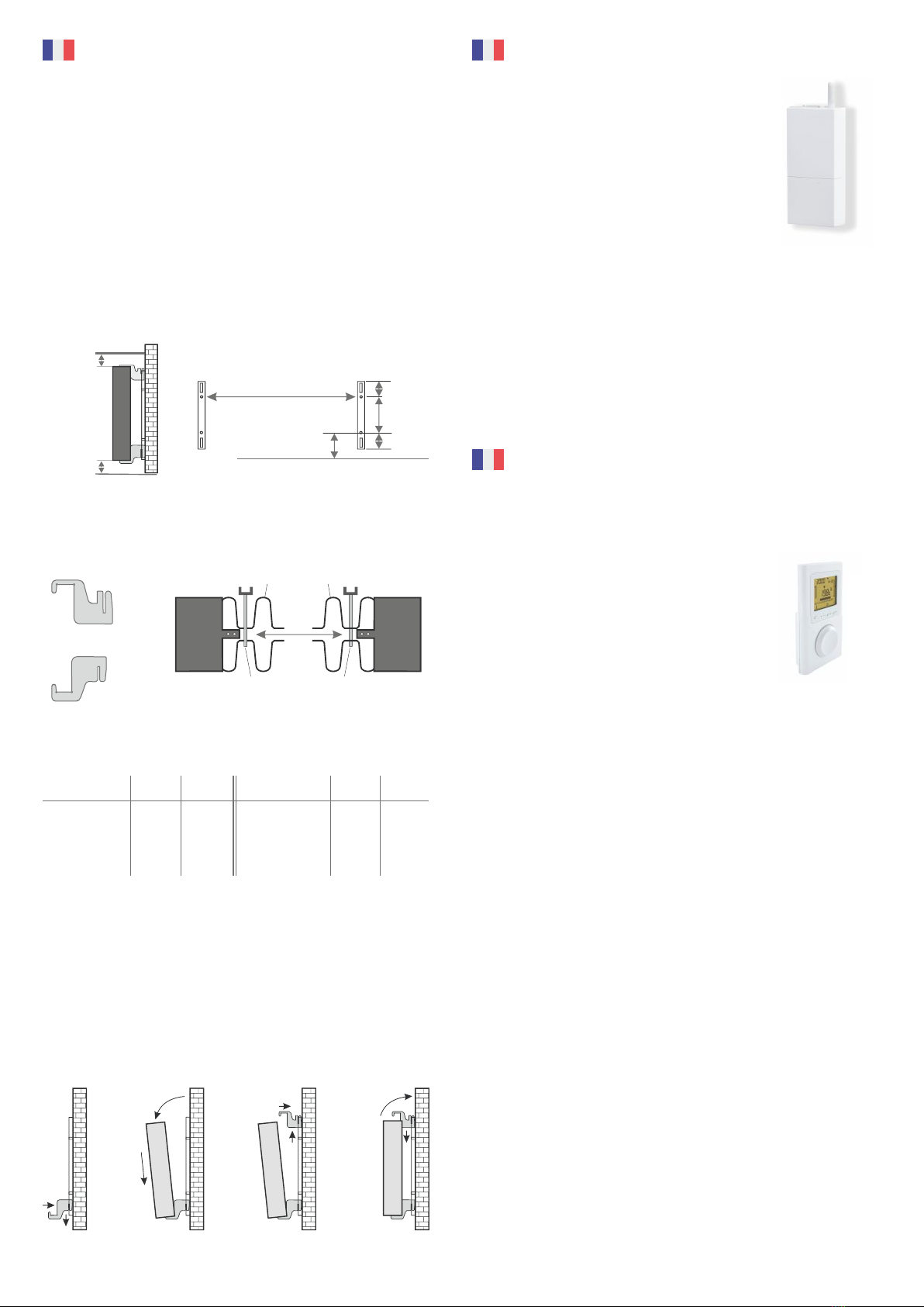
Seul le support mural fourni doit être uti lisé pour réaliser le montage mural! En
cas de montage et d‘utilisation dans des pièces humides, respectez
impérativement les dispositions actuelles, conformément à la norme VDE 0100
parti e 701.
L‘appareil ne doit pas être installé sous une prise électrique murale. Afin d‘éviter
une augmentati on trop importante de la température au niveau de la prise
murale, il est également nécessaire de respecter une certaine distance de
sécurité entre cett e prise et le radiateur. Cett e distance est calculée en fonction
de la qualité du matériel et de la résistance à la chaleur de la prise en question;
nous ne pouvons donc pas l‘estimer. Nous déclinons toute responsabilité en cas
de mauvaise manipulati on et d‘éventuels dommages en résultant. En cas de
doute, consultez un spécialiste avant de procéder au montage. En foncti on de la
nature et de l‘état du matériau mural, utilisez des vis et des chevilles appropriées.
Lorsque vous orientez le support mural et le radiateur, respectez toujours les
distances minimales indiquées (voir les illustrati ons suivantes).
Tous les radiateurs sont équipés de quatre supports en résistants à la
température, ce qui garantit leur fixation optimale. Faites attention à positionner
correctement les supports en supérieur (repère 1) et inférieur (repère 2) sur le
radiateur (voir les illustrations suivantes).
Le tableau de mesures décliné selon le type de radiateur vous permet d‘obtenir
le bon positionnement des glissières en forme de U et des supports en afin
d‘accrocher et de fixer correctement le radiateur.
Procédez comme suit pour réaliser le montage:
1. Fixez les deux glissières en forme de U sur le mur en respectant les distances
minimales en fonction de la mesure X/Y spécifique au type de radiateur.
2. Placez les deux supports en signalés par le repère 2 en bas des glissières en
forme de U.
3. Accrochez ensuite le radiateur aux supports en inférieurs et inclinez-le vers
l‘avant. Maintenez le radiateur!
4. Placez les deux supports en signalés par le repère 1 en haut des glissières en
forme de U et remontez-les provisoirement.
5. Positionnez enfin le radiateur à la verticale puis appuyez sur les supports en
vers le bas jusqu‘à ce que le radiateur soit totalement fixé.
Instructions relatives au thermostat
sans fil (récepteuer)
Instructions relatives au thermostat
sans fil (récepteuer)
Formation à l‘utilisation d‘un émetteur domotique
Sur le récepteur, appuyez plus de 3 secondes sur le bou-
ton, jusqu‘à ce que le voyant de commande commence à
clignoter.
Deux modes de fonctionnement sont possibles:
1. Clignotement lent: Interrupteur Marche/Arrêt
2. Clignotement rapide: Émetteur
Changement de mode
Appuyez brièvement sur le bouton du récepteur. Passez l‘émetteur en mode de
configuration. Vérifiez que le voyant de commande du récepteur ne clignote
plus.
Supprimer les attributions
Pour supprimer tous les produits attribués, appuyez environ 30 secondes sur le
bouton du récepteur, jusqu‘à ce que le voyant de commande clignote
brièvement. Tous les émetteurs sont à présent supprimés. Vous trouverez des
informations détaillées sur l‘émetteur sans fil dans la description jointe, le cas
échéant.
Fonctionnement
Protocole radio bidirectionnel sur fréquence radio 868 MHz. La portée atteint
entre 100 et 300 m (sans obstacle). Fixation au mur ou mobile dans la pièce.
Paramètres du régulateur d’ambiance pour Marche/Arrêt
et paramètres de base
Touches de réglage +/- avec paramètres programmables pour:
- Programmation journalière/hebdomadaire
- Détection des fenêtres ouvertes
- Signalement de présence (avec signalement supplémentaire de mouvements)
- Régulation de la température ambiante avec affichage à l’écran
- Signal sonore lors de la mise sous/hors tension
- Affichage de la température environnante
- Affichage de la consommation d’énergie (en kWh) des radiateurs électriques
raccordés
- Programme de vacances
- Hiver
Vous trouverez des informations détaillées sur les paramètres de l‘émetteur sans
fil dans la description jointe, le cas échéant.
Fonction détection d’ouverture
Les radiateurs équipés de récepteurs radio X3D doivent désormais être équipés
d'une fonction d'arrêt temporaire et ce afin de se conformer à la directive
européenne 2009/125/CE.
Pour ce faire, vous pouvez vous procurer auprès de la sté DELTA DORE un
détecteur d'ouverture sans fil de type "DO BL Tyxal+" (référence 6412288) ou
"MDO BL Tyxal+" (référence 6412305). Des instructions d'appairage sont
fournies avec le détecteur mais étant donné que nous ne commercialisons pas
pas ce type d'accessoire, nous ne serons pas en mesure de vous aider pour la
mise en route de l'ensemble.
Ill. 2
10 cm
8 cm
Mesure X
Mesure Y
190 mm
90 mm
90 mm
Ill. 1
Cote de montage
X
1
2
haut
bas
Ailee Ailee
Pare à
suspendre
Pare à
suspendre
Type de chauffage Mesure X Mesure Y
MINI 650 232 405
COMPACT 1300 466 405
MIDI 1950 766 405
Type de chauffage Mesure X Mesure Y
en mm en mmen mm en mm
MAXI 2450 1066 405
SLIM 1200 766 120
SLIM 1600 1066 120
SLIM TALL 1600 232 1040
1
22
1
2
1
2
2
1
2
1
2
2
1
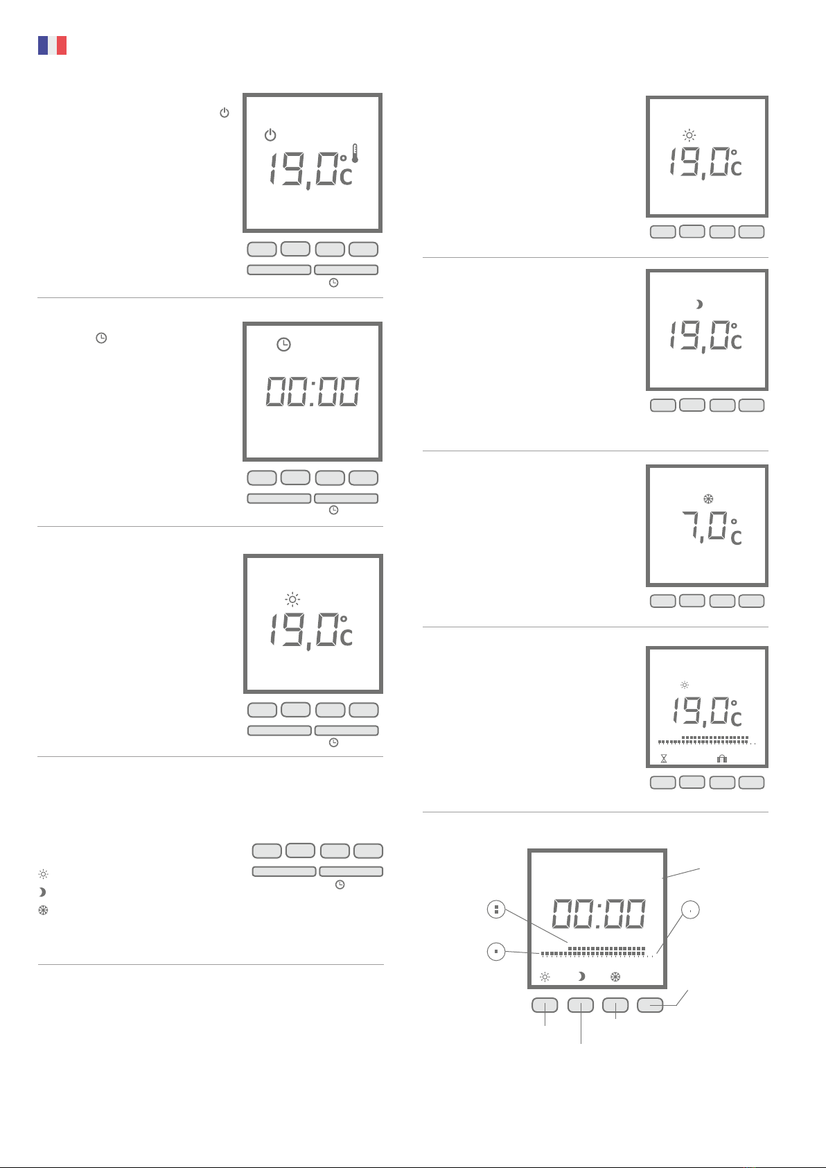
Si l‘appareil se trouve en mode de foncti-
onnement ARRÊT, le symbole suivant ___
apparaît à l‘écran.
4.1.1 Fonctionnement permanent en mode
Confort
L‘appareil cherche en permanence à atteindre la
température définie.
Vous pouvez définir la température par incré-
ments de 0,5 °C (de + 5 à + 30 °C) à l‘aide de la
touche + ou –.
4.1.2 Fonctionnement permanent en mode
Économique
La diminution de température souhaitée est
définie dans le menu de configuration 1. L‘appareil
cherche en permanence à atteindre la tempéra-
ture définie.
Vous pouvez définir la température par
incréments de 0,5°C (de + 5 à + 30°C) à l‘aide de la
touche + ou –.
Si cette valeur ne peut pas être modifiée, le menu
de configuration 1 doit être réglé sur "----" comme
décrit en 6.1.
4.1.3 Hors-gel permanent
Avec ce mode de fonctionnement, l‘appareil
cherche en permanence à atteindre la tempéra-
ture définie.
Vous pouvez définir la température par incré-
ments de 0,5°C (de + 5 à + 15°C) à l‘aide de la
touche + ou –.
4.1.4 Programmation AUTO
Ce mode permet à l‘appareil de fonctionner de
manière autonome selon la programmation éta-
blie. L‘heure qu‘il est et son paramétrage Confort,
Économique ou Hors-gel clignotent à l‘écran.
En mode de fonctionnement ARRÊT, appuyer
sur la touche .
L‘affichage des jours clignote.
Sélectionnez le jour souhaité à l‘aide de la
touche + ou –. Confirmez en appuyant sur OK,
puis réglez l‘heure et les minutes. Appuyez
sur la touche Marche-Arrêt pour quitter le
mode de paramétrage.
Remarque:
1 = Lundi 5 = Vendredi
2 = Mardi 6 = Samedi
3 = Mercredi 7 = Dimanche
4 = Jeudi
Lors de la première mise en service, chaque
jour dispose du programme CONFORT de
8 h 00 à 22 h 00 et du programme ÉCONO-
MIQUE de 22 h 00 à 8 h 00.
Le symbole ON affiché à l‘écran indique que
l‘appareil fonctionne.
Appuyez sur la touche i pour afficher la
température ambiante ou la température
définie. (Vous pouvez effectuer les réglages
dans le menu de configuration 6.4.)
La touche MODE est uniquement activée une fois l‘appareil mis sous tension en
appuyant sur la touche Marche-Arrêt.
La touche MODE permet de sélectionner les différents modes de fonction-
nement.
CONFORT
NUIT
HORS-GEL
AUTO avec programmation
Remarque: orientation du capteur de température
Le capteur de température est fixé sur une attache située en bas du radiateur. Si
l‘appareil est disposé dans un renfoncement ou dans un coin qui occasionne des
conséquences sur la température ambiante et la température mesurée, il est
possible de le retirer de son emplacement. Il est possible d‘augmenter l‘écart
entre le capteur et le chauffage en tournant le câble d‘alimentation du capteur. Il
est également possible d‘effectuer le paramétrage du point 2 du menu.
Instructions relatives au régulateur d‘ambiance
PROG
Marche-Arrêt
Marche-Arrêt
Marche-Arrêt
Marche-Arrêt
Mode
Mode
Mode
Mode
1. Affichage en mode de fonctionnement ARRÊT
2. Réglage de l‘heure
OK
1
2
3
4
5
6
7
►
+-
➘
3. Première mise en service
i+-
ON
4. Utilisation et choix du mode de fonctionnement
AUTO
➘
i+-
4.1 Explication des modes de fonctionnement
i+-
i+-
1
2
3
4
5
6
7
►
Oh 2 4 6 8 10 12 14 16 18 20 22 24
AUTO
PROG i
OK
1
2
3
4
5
6
7
►
Jour de la
semaine
PROG
Oh 2 4 6 8 10 12 14 16 18 20 22 24
Appuyer pour 1 h
«Hors-gel»
Appuyer pour 1 h
«Confort»
Confirmer puis
modification/pa-
ramétrage du jour
suivant
Appuyer pour 1 h
«Économique»
une barres =
«Économique»
deux barres =
«Confort» aucune barre =
«Hors-Gel»
5. Modifier l‘affichage des paramètres de la programmation AUTO
6. Menu de configuration
PROG
10 sec.
➘
Dans le menu de configuration, il est possible
d‘effectuer les réglages suivants:
- Définir la valeur de consigne du mode Éco-
nomique
- Corriger la température mesurée
- Définir la durée du rétroéclairage
- Choisir l‘affichage de la température en
mode AUTO
- Fonction détection d’ouverture
- Fonction d’anticipation
- Consulter le numéro de produit
Entrer dans le menu de configuration
En mode ARRÊT, ouvrez le premier menu de
configuration en appuyant 10 secondes sur
l‘interrupteur Marche-Arrêt.
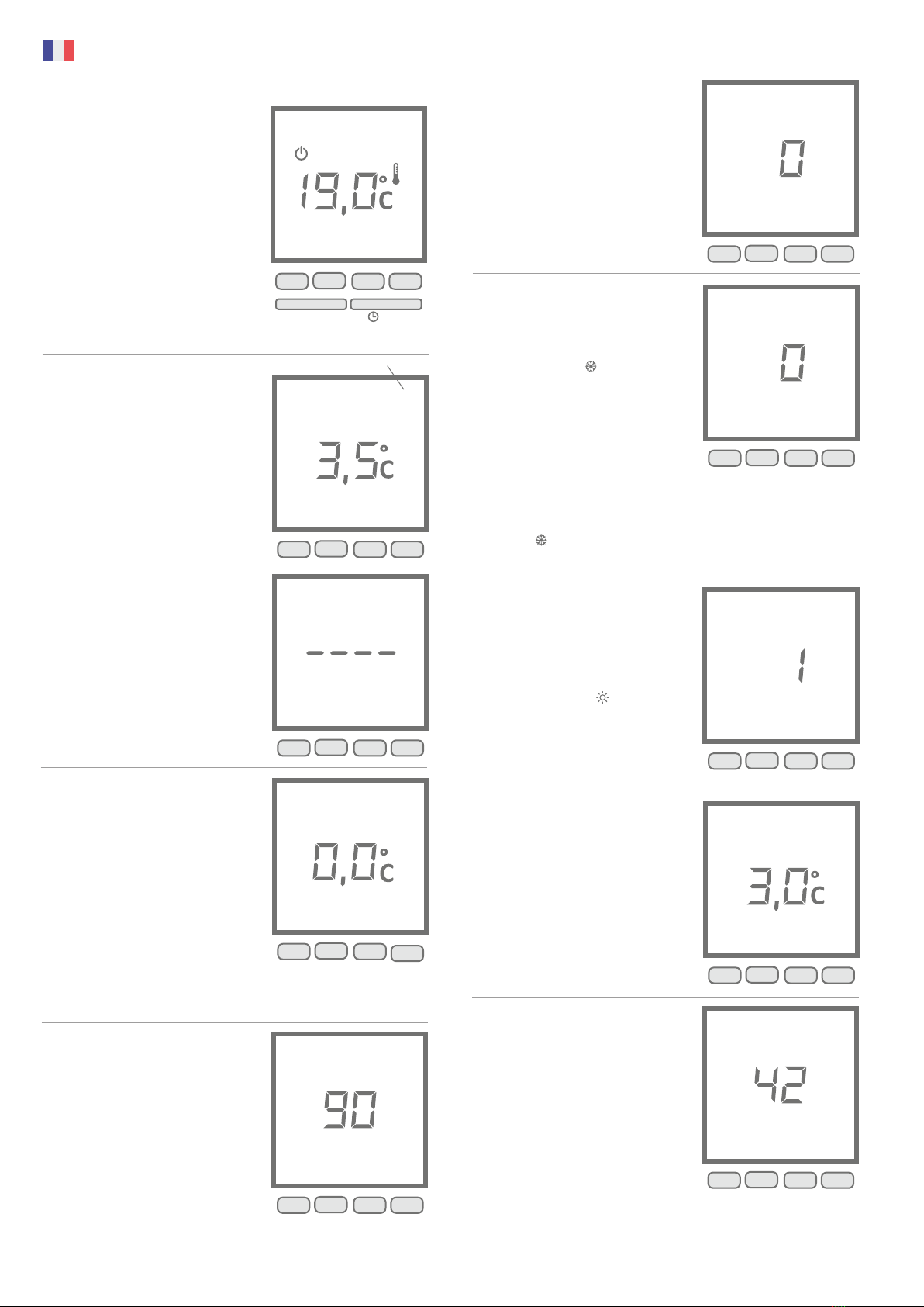
Menu 4
6.4 Choisir l‘affichage de la température en
mode AUTO (programmation)
0 = Affichage permanent de la température
ambiante.
1 = Affichage permanent de la température
définie.
Modifier à l‘aide de la touche + ou –.
Confirmer ensuite avec la touche OK.
Menu 5
6.5 Fonction détection d’ouverture
La détection d’ouverture se fait sur chute
rapide de température.
Dans ce cas, le symbole clignote à l’écran et
la température de consigne Hors gel est
affichée.
0 = Pas de détection d’ouverture
1 = Détection d’ouverture active
Pour modifier, appuyez sur les touches + ou -,
puis appuyez sur la touche OK pour valider et
passer au réglage suivant.
L’ouverture n’est pas détectée en mode Arrêt.
La détection peut être annulée en appuyant
sur la touche .
Menu 5
6.6 Fonction d’anticipation
Cette fonction permet d’obtenir la tempéra-
ture souhaitée au moment souhaité (transi-
tion Eco > Confort).
L’anticipation en cours est signalée par le
clignotement du symbole .
0 = Pas d’anticipation
1 = Anticipation active
Pour modifier, appuyez sur les touches + ou -,
puis appuyez sur la touche OK pour valider et
passer au réglage suivant.
Réglage de la pente (si anticipation active)
De 1°C à 6°C, par pas de 0,5°C.
Si la température est atteinte trop tôt, dimi-
nuer la valeur.
Si la température est atteinte trop tard,
augmenter la valeur.
Menu quitter
6.5 Numéro de produit
Ce menu permet d‘afficher le numéro du
produit. Appuyez sur la touche OK pour
quitter le mode de configuration.
Menu 1
6.1 Définir la valeur de consigne du mode
Économique
Valeur standard du mode Économique =
valeur de la température du mode CONFORT
moins 3,5 °C. Vous pouvez modifier cette
diminution par incréments de 0,5°C, de 0 à
10°C. Modifier à l‘aide de la touche + ou –.
Confirmer ensuite avec la touche OK.
Appuyer sur la touche + jusqu'à ce que «----»
apparaisse sur l'affichage pour autoriser le
changement de valeur par l'utilisateur.
Reportez-vous à 4.1.2 Fonctionnement
permanent en mode Économique
Menu 2
6.2 Corriger la température mesurée
Si la température ambiante diffère de la
température mesurée sur le radiateur
(affichage sur l'appareil), utilisez le menu 2.
Une valeur de compensation pour le capteur
de mesure de -5 ° C à + 5 ° C peut être saisie ici
(par pas de 0,1 ° C).
Exemple: • température ambiante = 21 ° C
• température mesurée. = 20 ° C
• Réglez + 1,0 ° C dans le Menu 2.
Modifier à l‘aide de la touche + ou –. Con-
firmer ensuite avec la touche OK.
Menu 3
6.3 Définir la durée du rétroéclairage
Il est possible de régler la durée de l‘éclairage
par incréments de 15 secondes, de 0 à 225
secondes.
La valeur par défaut est de 90 secondes.
Modifier à l‘aide de la touche + ou –.
Confirmer ensuite avec la touche OK.
1
2
3
4
5
6
7
►
N° du menu
OK+-
1
2
3
4
5
6
7
►
OK+-
➘
1
2
3
4
5
6
7
►
OK
+-
1
2
3
4
5
6
7
►
OK+-
1
2
3
4
5
6
7
►
OK+-
OK
Instructions relatives au régulateur d‘ambiance
Marche-Arrêt Mode
1
2
3
4
5
6
7
OK+-
►
1
2
3
4
5
6
7
►
OK+-
1
2
3
4
5
6
7
►
OK+-

7.1 Paramètre de température limité dans
le temps
Il est possible de définir une valeur de
température pour une durée déterminée en
appuyant sur la touche .
Réglez la température souhaitée (de + 5°C
à + 30°C) à l‘aide de la touche + ou –. Con-
firmez en appuyant sur OK puis réglez la
durée.
Réglez la durée souhaitée (de 30 minutes
à 72 heures) à l‘aide de la touche + ou –
(p. ex. 1 h 30) et confirmez en appuyant
sur OK. Appuyez à nouveau sur la touche OK
pour supprimer le réglage limité de la
température.
7.2 Sécurité enfant
Vous pouvez bloquer le clavier en ap-
puyant simultanément sur les deux tou-
ches centrales pendant 5 secondes. Une
clé apparaît brièvement à l‘écran. Pour
déverrouiller le clavier, appuyez à nouveau
simultanément sur les touches + et –.
7.3 Fonction d‘absence
Réglez votre appareil en mode Hors-gel
entre 1 et 365 jours en appuyant sur la
touche .
Ajustez le nombre de jours d‘absence à
l‘aide de la touche + ou – puis confirmez
en appuyant sur OK. Appuyez à nouveau
sur la touche OK pour supprimer le foncti-
onnement en cas d‘absence.
7. Paramètres supplémentaires
➘
PROG
OK
➘
PROG
➘
➘
PROG
Instructions relatives au régulateur d‘ambiance
Model identfier(s):
Item Symbol Value Unit Item Unit
Nominal heat out-
put Pnom 2,45 kW manual heat charge control, with integrated thermostat N/A
Minimum heat
output (indicative) Pmin 2,45 kW manual heat charge control with room and/or outdoor
temperature feedback N/A
Maximum contin-
uous heat output Pmax,c 1,84 kW electronic heat charge control with room and/or
outdoor temperature feedback N/A
Auxiliary electri-city
consumption fan assisted heat output N/A
At nominal heat
output elmax 0,0075 kW
At minimum heat
output elmin 0,0075 kW single stage heat output and no room temperature
control no
In standby mode elSB 0,0011 kW Two or more manual stages, no room temperature
control no
with mechanic thermostat room temperature control no
with electronic room temperature control no
electronic room temperature control plus day timer no
electronic room temperature control plus week timer yes
room temperature control, with presence detection no
room temperature control, with open window detection yes
with distance control option no
with adaptive start control yes
with working time limitation no
with black bulb sensor no
Contact details
Other control options (multiple selections possible)
Table 2 of the COMMISSION REGULATION (EU) 2015/1188 as of 28 April 2015
Information requirements for electric local space heaters
T7-ITRd / TFLH7-ITRd / MAXI 2450-ITRd
Heat output Type of heat input, for electric storage local space heaters only
(select one)
Type of heat output/room temperature control (select one)
Thermotec AG | Arnsdorf 26 | 02894 Vierkirchen | Germany
Model identfier(s):
Item Symbol Value Unit Item Unit
Nominal heat out-
put Pnom 1,30 kW manual heat charge control, with integrated thermostat N/A
Minimum heat
output (indicative) Pmin 1,30 kW manual heat charge control with room and/or outdoor
temperature feedback N/A
Maximum contin-
uous heat output Pmax,c 0,98 kW electronic heat charge control with room and/or
outdoor temperature feedback N/A
Auxiliary electri-city
consumption fan assisted heat output N/A
At nominal heat
output elmax 0,0075 kW
At minimum heat
output elmin 0,0075 kW single stage heat output and no room temperature
control no
In standby mode elSB 0,0011 kW Two or more manual stages, no room temperature
control no
with mechanic thermostat room temperature control no
with electronic room temperature control no
electronic room temperature control plus day timer no
electronic room temperature control plus week timer yes
room temperature control, with presence detection no
room temperature control, with open window detection yes
with distance control option no
with adaptive start control yes
with working time limitation no
with black bulb sensor no
Contact details
Other control options (multiple selections possible)
Table 2 of the COMMISSION REGULATION (EU) 2015/1188 as of 28 April 2015
Information requirements for electric local space heaters
T3-ITRd / TFLH3-ITRd / COMPACT 1300-ITRd
Heat output Type of heat input, for electric storage local space heaters only
(select one)
Type of heat output/room temperature control (select one)
Thermotec AG | Arnsdorf 26 | 02894 Vierkirchen | Germany
Model identfier(s):
Item Symbol Value Unit Item Unit
Nominal heat out-
put Pnom 2,00 kW manual heat charge control, with integrated thermostat N/A
Minimum heat
output (indicative) Pmin 2,00 kW manual heat charge control with room and/or outdoor
temperature feedback N/A
Maximum contin-
uous heat output Pmax,c 1,50 kW electronic heat charge control with room and/or
outdoor temperature feedback N/A
Auxiliary electri-city
consumption fan assisted heat output N/A
At nominal heat
output elmax 0,0075 kW
At minimum heat
output elmin 0,0075 kW single stage heat output and no room temperature
control no
In standby mode elSB 0,0011 kW Two or more manual stages, no room temperature
control no
with mechanic thermostat room temperature control no
with electronic room temperature control no
electronic room temperature control plus day timer no
electronic room temperature control plus week timer yes
room temperature control, with presence detection no
room temperature control, with open window detection yes
with distance control option no
with adaptive start control yes
with working time limitation no
with black bulb sensor no
Contact details
Other control options (multiple selections possible)
Table 2 of the COMMISSION REGULATION (EU) 2015/1188 as of 28 April 2015
Information requirements for electric local space heaters
T14-ITRd / TFLH14-ITRd / SLIM 2000-ITRd
Heat output Type of heat input, for electric storage local space heaters only
(select one)
Type of heat output/room temperature control (select one)
Thermotec AG | Arnsdorf 26 | 02894 Vierkirchen | Germany
Model identfier(s):
Item Symbol Value Unit Item Unit
Nominal heat out-
put Pnom 1,20 kW manual heat charge control, with integrated thermostat N/A
Minimum heat
output (indicative) Pmin 1,20 kW manual heat charge control with room and/or outdoor
temperature feedback N/A
Maximum contin-
uous heat output Pmax,c 0,90 kW electronic heat charge control with room and/or
outdoor temperature feedback N/A
Auxiliary electri-city
consumption fan assisted heat output N/A
At nominal heat
output elmax 0,0075 kW
At minimum heat
output elmin 0,0075 kW single stage heat output and no room temperature
control no
In standby mode elSB 0,0011 kW Two or more manual stages, no room temperature
control no
with mechanic thermostat room temperature control no
with electronic room temperature control no
electronic room temperature control plus day timer no
electronic room temperature control plus week timer yes
room temperature control, with presence detection no
room temperature control, with open window detection yes
with distance control option no
with adaptive start control yes
with working time limitation no
with black bulb sensor no
Contact details
Other control options (multiple selections possible)
Table 2 of the COMMISSION REGULATION (EU) 2015/1188 as of 28 April 2015
Information requirements for electric local space heaters
T12-ITRd / TFLH12-ITRd / SLIM 1200-ITRd
Heat output Type of heat input, for electric storage local space heaters only
(select one)
Type of heat output/room temperature control (select one)
Thermotec AG | Arnsdorf 26 | 02894 Vierkirchen | Germany
Model identfier(s):
Item Symbol Value Unit Item Unit
Nominal heat out-
put Pnom 0,65 kW manual heat charge control, with integrated thermostat N/A
Minimum heat
output (indicative) Pmin 0,65 kW manual heat charge control with room and/or outdoor
temperature feedback N/A
Maximum contin-
uous heat output Pmax,c 0,49 kW electronic heat charge control with room and/or
outdoor temperature feedback N/A
Auxiliary electri-city
consumption fan assisted heat output N/A
At nominal heat
output elmax 0,0075 kW
At minimum heat
output elmin 0,0075 kW single stage heat output and no room temperature
control no
In standby mode elSB 0,0011 kW Two or more manual stages, no room temperature
control no
with mechanic thermostat room temperature control no
with electronic room temperature control no
electronic room temperature control plus day timer no
electronic room temperature control plus week timer yes
room temperature control, with presence detection no
room temperature control, with open window detection yes
with distance control option no
with adaptive start control yes
with working time limitation no
with black bulb sensor no
Contact details
Other control options (multiple selections possible)
Table 2 of the COMMISSION REGULATION (EU) 2015/1188 as of 28 April 2015
Information requirements for electric local space heaters
T1-ITRd / TFLH1-ITRd / Mini 650-ITRd
Heat output Type of heat input, for electric storage local space heaters only
(select one)
Type of heat output/room temperature control (select one)
Thermotec AG | Arnsdorf 26 | 02894 Vierkirchen | Germany
Model identfier(s):
Item Symbol Value Unit Item Unit
Nominal heat out-
put Pnom 1,60 kW manual heat charge control, with integrated thermostat N/A
Minimum heat
output (indicative) Pmin 1,60 kW manual heat charge control with room and/or outdoor
temperature feedback N/A
Maximum contin-
uous heat output Pmax,c 1,20 kW electronic heat charge control with room and/or
outdoor temperature feedback N/A
Auxiliary electri-city
consumption fan assisted heat output N/A
At nominal heat
output elmax 0,0075 kW
At minimum heat
output elmin 0,0075 kW single stage heat output and no room temperature
control no
In standby mode elSB 0,0011 kW Two or more manual stages, no room temperature
control no
with mechanic thermostat room temperature control no
with electronic room temperature control no
electronic room temperature control plus day timer no
electronic room temperature control plus week timer yes
room temperature control, with presence detection no
room temperature control, with open window detection yes
with distance control option no
with adaptive start control yes
with working time limitation no
with black bulb sensor no
Contact details
Other control options (multiple selections possible)
Table 2 of the COMMISSION REGULATION (EU) 2015/1188 as of 28 April 2015
Information requirements for electric local space heaters
T10-ITRd / TFLH10-ITRd / SLIM TALL 1600-ITRd
Heat output Type of heat input, for electric storage local space heaters only
(select one)
Type of heat output/room temperature control (select one)
Thermotec AG | Arnsdorf 26 | 02894 Vierkirchen | Germany

Modelkennung(en):
Angabe Symbol Wert Ein-
heit Angabe Einheit
Nennwärmeleis-
tung Pnom 2,45 kW manuelle Reglung der Wärmezufuhr mit integ-riertem
Thermostat N/A
Mindeswärmeleis-
tung (Richtwert) Pmin 2,45 kW manuelle Reglung der Wärmezufuhr mit Rück- meldung
der Raum- und/oder Außentemperatur N/A
Maximale konti-
nuierlicher Wärme-
leistung
Pmax,c 2,21 kW elektronische Reglung der Wärmezufuhr mit
Rückmeldung der Raum- und/oder Außentempe- ratur N/A
Hilfsstromver-
brauch Wärmeabgabe mit Gebläseunterstützung N/A
Bei Nennwärme-
leistung elmax 0,0075 kW
Bei Mindestwär-
meleistung elmin 0,0075 kW einstufige Wärmeleistung, keine Raumtempera-
turkontrolle nein
Im Bereitschafts-
zustand elSB 0,0011 kW zwei oder mehr manuell einstellbare Stufen,
keine Raumtemperaturkontrolle nein
Raumtemperaturkontrolle mit mechanischem
Thermostat nein
mit elektrischer Raumtemperaturkontrolle nein
elekronischer Raumtemperatrukontrolle und Ta-
geszeitregelung nein
elektronischer Raumtemperatrukontrolle und Wo-
chentagsregelung ja
Raumtemperaturkontrolle mit Präsenserkennung nein
Raumtemperatrukontrolle mit Erkennung offener
Fenster Ja
mit Fernbedienungsoption nein
mit adaptiver Regelung des Heizbeginns Ja
mit Betriebszeitbegrenzung nein
mit Schwarzkugelsensor nein
Kontaktangaben Thermotec AG | Arnsdorf 26 | 02894 Vierkirchen | Deutschland
Sonstige Reglungsoptionen (Mehrfachnennung mög-
lich)
Tabelle 2 zur VERORDNUNG (EU) 2015/1188 DER KOMMISSION vom 28. April 2015
Erforderliche Angaben zu elektrischen Einzelraumheizgeräten
T7-ITRd / TFLH7-ITRd / MAXI 2450-ITRd
Wärmeleistung Nur bei elektrischen Speicher-Einzelraumheizgeräten: Art der
Reglung der Wärmezufuhr (bitte eine Möglichkeit auswählen)
Art der Wärmeleistung/Raumtemperaturkontrolle (bitte eine
Möglichkeit auswählen)
Modelkennung(en):
Angabe Symbol Wert Ein-
heit Angabe Einheit
Nennwärmeleis-
tung Pnom 2,00 kW manuelle Reglung der Wärmezufuhr mit integ-riertem
Thermostat N/A
Mindeswärmeleis-
tung (Richtwert) Pmin 2,00 kW manuelle Reglung der Wärmezufuhr mit Rück- meldung
der Raum- und/oder Außentemperatur N/A
Maximale konti-
nuierlicher Wärme-
leistung
Pmax,c 1,50 kW elektronische Reglung der Wärmezufuhr mit
Rückmeldung der Raum- und/oder Außentempe- ratur N/A
Hilfsstromver-
brauch Wärmeabgabe mit Gebläseunterstützung N/A
Bei Nennwärme-
leistung elmax 0,0075 kW
Bei Mindestwär-
meleistung elmin 0,0075 kW einstufige Wärmeleistung, keine Raumtempera-
turkontrolle nein
Im Bereitschafts-
zustand elSB 0,0011 kW zwei oder mehr manuell einstellbare Stufen,
keine Raumtemperaturkontrolle nein
Raumtemperaturkontrolle mit mechanischem
Thermostat nein
mit elektrischer Raumtemperaturkontrolle nein
elekronischer Raumtemperatrukontrolle und Ta-
geszeitregelung nein
elektronischer Raumtemperatrukontrolle und Wo-
chentagsregelung ja
Raumtemperaturkontrolle mit Präsenserkennung nein
Raumtemperatrukontrolle mit Erkennung offener
Fenster Ja
mit Fernbedienungsoption nein
mit adaptiver Regelung des Heizbeginns Ja
mit Betriebszeitbegrenzung nein
mit Schwarzkugelsensor nein
Kontaktangaben Thermotec AG | Arnsdorf 26 | 02894 Vierkirchen | Deutschland
Sonstige Reglungsoptionen (Mehrfachnennung mög-
lich)
Tabelle 2 zur VERORDNUNG (EU) 2015/1188 DER KOMMISSION vom 28. April 2015
Erforderliche Angaben zu elektrischen Einzelraumheizgeräten
T14-ITRd / TFLH14-ITRd / SLIM 2000-ITRd
Wärmeleistung Nur bei elektrischen Speicher-Einzelraumheizgeräten: Art der
Reglung der Wärmezufuhr (bitte eine Möglichkeit auswählen)
Art der Wärmeleistung/Raumtemperaturkontrolle (bitte eine
Möglichkeit auswählen)
Modelkennung(en):
Angabe Symbol Wert Ein-
heit Angabe Einheit
Nennwärmeleis-
tung Pnom 1,95 kW manuelle Reglung der Wärmezufuhr mit integ-riertem
Thermostat N/A
Mindeswärmeleis-
tung (Richtwert) Pmin 1,95 kW manuelle Reglung der Wärmezufuhr mit Rück- meldung
der Raum- und/oder Außentemperatur N/A
Maximale konti-
nuierlicher Wärme-
leistung
Pmax,c 1,76 kW elektronische Reglung der Wärmezufuhr mit
Rückmeldung der Raum- und/oder Außentempe- ratur N/A
Hilfsstromver-
brauch Wärmeabgabe mit Gebläseunterstützung N/A
Bei Nennwärme-
leistung elmax 0,0075 kW
Bei Mindestwär-
meleistung elmin 0,0075 kW einstufige Wärmeleistung, keine Raumtempera-
turkontrolle nein
Im Bereitschafts-
zustand elSB 0,0011 kW zwei oder mehr manuell einstellbare Stufen,
keine Raumtemperaturkontrolle nein
Raumtemperaturkontrolle mit mechanischem
Thermostat nein
mit elektrischer Raumtemperaturkontrolle nein
elekronischer Raumtemperatrukontrolle und Ta-
geszeitregelung nein
elektronischer Raumtemperatrukontrolle und Wo-
chentagsregelung ja
Raumtemperaturkontrolle mit Präsenserkennung nein
Raumtemperatrukontrolle mit Erkennung offener
Fenster Ja
mit Fernbedienungsoption nein
mit adaptiver Regelung des Heizbeginns Ja
mit Betriebszeitbegrenzung nein
mit Schwarzkugelsensor nein
Kontaktangaben Thermotec AG | Arnsdorf 26 | 02894 Vierkirchen | Deutschland
Sonstige Reglungsoptionen (Mehrfachnennung mög-
lich)
Tabelle 2 zur VERORDNUNG (EU) 2015/1188 DER KOMMISSION vom 28. April 2015
Erforderliche Angaben zu elektrischen Einzelraumheizgeräten
T5-ITRd / TFLH5-ITRd / MIDI 1950-ITRd
Wärmeleistung Nur bei elektrischen Speicher-Einzelraumheizgeräten: Art der
Reglung der Wärmezufuhr (bitte eine Möglichkeit auswählen)
Art der Wärmeleistung/Raumtemperaturkontrolle (bitte eine
Möglichkeit auswählen)
Modelkennung(en):
Angabe Symbol Wert Ein-
heit Angabe Einheit
Nennwärmeleis-
tung Pnom 1,60 kW manuelle Reglung der Wärmezufuhr mit integ-riertem
Thermostat N/A
Mindeswärmeleis-
tung (Richtwert) Pmin 1,60 kW manuelle Reglung der Wärmezufuhr mit Rück- meldung
der Raum- und/oder Außentemperatur N/A
Maximale konti-
nuierlicher Wärme-
leistung
Pmax,c 1,20 kW elektronische Reglung der Wärmezufuhr mit
Rückmeldung der Raum- und/oder Außentempe- ratur N/A
Hilfsstromver-
brauch Wärmeabgabe mit Gebläseunterstützung N/A
Bei Nennwärme-
leistung elmax 0,0075 kW
Bei Mindestwär-
meleistung elmin 0,0075 kW einstufige Wärmeleistung, keine Raumtempera-
turkontrolle nein
Im Bereitschafts-
zustand elSB 0,0011 kW zwei oder mehr manuell einstellbare Stufen,
keine Raumtemperaturkontrolle nein
Raumtemperaturkontrolle mit mechanischem
Thermostat nein
mit elektrischer Raumtemperaturkontrolle nein
elekronischer Raumtemperatrukontrolle und Ta-
geszeitregelung nein
elektronischer Raumtemperatrukontrolle und Wo-
chentagsregelung ja
Raumtemperaturkontrolle mit Präsenserkennung nein
Raumtemperatrukontrolle mit Erkennung offener
Fenster Ja
mit Fernbedienungsoption nein
mit adaptiver Regelung des Heizbeginns Ja
mit Betriebszeitbegrenzung nein
mit Schwarzkugelsensor nein
Kontaktangaben Thermotec AG | Arnsdorf 26 | 02894 Vierkirchen | Deutschland
Sonstige Reglungsoptionen (Mehrfachnennung mög-
lich)
Tabelle 2 zur VERORDNUNG (EU) 2015/1188 DER KOMMISSION vom 28. April 2015
Erforderliche Angaben zu elektrischen Einzelraumheizgeräten
T10-ITRd / TFLH10-ITRd / SLIM TALL 1600-ITRd
Wärmeleistung Nur bei elektrischen Speicher-Einzelraumheizgeräten: Art der
Reglung der Wärmezufuhr (bitte eine Möglichkeit auswählen)
Art der Wärmeleistung/Raumtemperaturkontrolle (bitte eine
Möglichkeit auswählen)
Modelkennung(en):
Angabe Symbol Wert Ein-
heit Angabe Einheit
Nennwärmeleis-
tung Pnom 1,30 kW manuelle Reglung der Wärmezufuhr mit integ-riertem
Thermostat N/A
Mindeswärmeleis-
tung (Richtwert) Pmin 1,30 kW manuelle Reglung der Wärmezufuhr mit Rück- meldung
der Raum- und/oder Außentemperatur N/A
Maximale konti-
nuierlicher Wärme-
leistung
Pmax,c 1,17 kW elektronische Reglung der Wärmezufuhr mit
Rückmeldung der Raum- und/oder Außentempe- ratur N/A
Hilfsstromver-
brauch Wärmeabgabe mit Gebläseunterstützung N/A
Bei Nennwärme-
leistung elmax 0,0075 kW
Bei Mindestwär-
meleistung elmin 0,0075 kW einstufige Wärmeleistung, keine Raumtempera-
turkontrolle nein
Im Bereitschafts-
zustand elSB 0,0011 kW zwei oder mehr manuell einstellbare Stufen,
keine Raumtemperaturkontrolle nein
Raumtemperaturkontrolle mit mechanischem
Thermostat nein
mit elektrischer Raumtemperaturkontrolle nein
elekronischer Raumtemperatrukontrolle und Ta-
geszeitregelung nein
elektronischer Raumtemperatrukontrolle und Wo-
chentagsregelung ja
Raumtemperaturkontrolle mit Präsenserkennung nein
Raumtemperatrukontrolle mit Erkennung offener
Fenster Ja
mit Fernbedienungsoption nein
mit adaptiver Regelung des Heizbeginns Ja
mit Betriebszeitbegrenzung nein
mit Schwarzkugelsensor nein
Kontaktangaben Thermotec AG | Arnsdorf 26 | 02894 Vierkirchen | Deutschland
Sonstige Reglungsoptionen (Mehrfachnennung mög-
lich)
Tabelle 2 zur VERORDNUNG (EU) 2015/1188 DER KOMMISSION vom 28. April 2015
Erforderliche Angaben zu elektrischen Einzelraumheizgeräten
T3-ITRd / TFLH3-ITRd / COMPACT 1300-ITRd
Wärmeleistung Nur bei elektrischen Speicher-Einzelraumheizgeräten: Art der
Reglung der Wärmezufuhr (bitte eine Möglichkeit auswählen)
Art der Wärmeleistung/Raumtemperaturkontrolle (bitte eine
Möglichkeit auswählen)
Modelkennung(en):
Angabe Symbol Wert Ein-
heit Angabe Einheit
Nennwärmeleis-
tung Pnom 1,20 kW manuelle Reglung der Wärmezufuhr mit integ-riertem
Thermostat N/A
Mindeswärmeleis-
tung (Richtwert) Pmin 1,20 kW manuelle Reglung der Wärmezufuhr mit Rück- meldung
der Raum- und/oder Außentemperatur N/A
Maximale konti-
nuierlicher Wärme-
leistung
Pmax,c 0,90 kW elektronische Reglung der Wärmezufuhr mit
Rückmeldung der Raum- und/oder Außentempe- ratur N/A
Hilfsstromver-
brauch Wärmeabgabe mit Gebläseunterstützung N/A
Bei Nennwärme-
leistung elmax 0,0075 kW
Bei Mindestwär-
meleistung elmin 0,0075 kW einstufige Wärmeleistung, keine Raumtempera-
turkontrolle nein
Im Bereitschafts-
zustand elSB 0,0011 kW zwei oder mehr manuell einstellbare Stufen,
keine Raumtemperaturkontrolle nein
Raumtemperaturkontrolle mit mechanischem
Thermostat nein
mit elektrischer Raumtemperaturkontrolle nein
elekronischer Raumtemperatrukontrolle und Ta-
geszeitregelung nein
elektronischer Raumtemperatrukontrolle und Wo-
chentagsregelung ja
Raumtemperaturkontrolle mit Präsenserkennung nein
Raumtemperatrukontrolle mit Erkennung offener
Fenster Ja
mit Fernbedienungsoption nein
mit adaptiver Regelung des Heizbeginns Ja
mit Betriebszeitbegrenzung nein
mit Schwarzkugelsensor nein
Kontaktangaben Thermotec AG | Arnsdorf 26 | 02894 Vierkirchen | Deutschland
Sonstige Reglungsoptionen (Mehrfachnennung mög-
lich)
Tabelle 2 zur VERORDNUNG (EU) 2015/1188 DER KOMMISSION vom 28. April 2015
Erforderliche Angaben zu elektrischen Einzelraumheizgeräten
T12-ITRd / TFLH12-ITRd / SLIM 1200-ITRd
Wärmeleistung Nur bei elektrischen Speicher-Einzelraumheizgeräten: Art der
Reglung der Wärmezufuhr (bitte eine Möglichkeit auswählen)
Art der Wärmeleistung/Raumtemperaturkontrolle (bitte eine
Möglichkeit auswählen)
Modelkennung(en):
Angabe Symbol Wert Ein-
heit Angabe Einheit
Nennwärmeleis-
tung Pnom 0,65 kW manuelle Reglung der Wärmezufuhr mit integ-riertem
Thermostat N/A
Mindeswärmeleis-
tung (Richtwert) Pmin 0,65 kW manuelle Reglung der Wärmezufuhr mit Rück- meldung
der Raum- und/oder Außentemperatur N/A
Maximale konti-
nuierlicher Wärme-
leistung
Pmax,c 0,59 kW elektronische Reglung der Wärmezufuhr mit
Rückmeldung der Raum- und/oder Außentempe- ratur N/A
Hilfsstromver-
brauch Wärmeabgabe mit Gebläseunterstützung N/A
Bei Nennwärme-
leistung elmax 0,0075 kW
Bei Mindestwär-
meleistung elmin 0,0075 kW einstufige Wärmeleistung, keine Raumtempera-
turkontrolle nein
Im Bereitschafts-
zustand elSB 0,0011 kW zwei oder mehr manuell einstellbare Stufen,
keine Raumtemperaturkontrolle nein
Raumtemperaturkontrolle mit mechanischem
Thermostat nein
mit elektrischer Raumtemperaturkontrolle nein
elekronischer Raumtemperatrukontrolle und Ta-
geszeitregelung nein
elektronischer Raumtemperatrukontrolle und Wo-
chentagsregelung ja
Raumtemperaturkontrolle mit Präsenserkennung nein
Raumtemperatrukontrolle mit Erkennung offener
Fenster Ja
mit Fernbedienungsoption nein
mit adaptiver Regelung des Heizbeginns Ja
mit Betriebszeitbegrenzung nein
mit Schwarzkugelsensor nein
Kontaktangaben
Sonstige Reglungsoptionen (Mehrfachnennung mög-
lich)
Tabelle 2 zur VERORDNUNG (EU) 2015/1188 DER KOMMISSION vom 28. April 2015
Erforderliche Angaben zu elektrischen Einzelraumheizgeräten
T1-ITRd / TFLH1-ITRd / Mini 650-ITRd
Wärmeleistung Nur bei elektrischen Speicher-Einzelraumheizgeräten: Art der
Reglung der Wärmezufuhr (bitte eine Möglichkeit auswählen)
Art der Wärmeleistung/Raumtemperaturkontrolle (bitte eine
Möglichkeit auswählen)
Thermotec AG | Arnsdorf 26 | 02894 Vierkirchen | Deutschland
Garane Zerfikat
warranty cerficate
Sebasan Heidrich
Gründer und Vorstand der Thermotec AG
www.thermotec.ag
Thermotec AG | Arnsdorf 26 | 02894 Vierkirchen | Deutschland
Phone: +49(0)3 58 27 78 93 30 | [email protected]
30 Jahre Garantie auf die Wärmeerzeugung und
die Bedienbarkeit des Grundgerätes
Mit dem Erwerb dieses Gerätes haben Sie sich für ein innovatives
Qualitätsprodukt der absoluten Spitzenklasse entschieden.
Wir bedanken uns für Ihr Vertrauen.
Die AeroFlow®- Produktfamilie der Thermotec AG steht
für ein gesundes Raumklima und kostenbewusstes Heizen.
Unsere jahrelange Entwicklungsarbeit sowie ein modernes
Produktionsverfahren sind die Voraussetzung für die Langlebigkeit
und hohe Wertbeständigkeit Ihres AeroFlow®- Produktes.

Other manuals for AeroFlow MINI 650
3
This manual suits for next models
6
Table of contents
Languages:
Other ThermoTec Heater manuals


Popular Heater manuals by other brands


 Service manual")


Futura
Futura ECO FAH600 Original operating instructions

Stavoklima
Stavoklima Nucleo 3000 Installation and operation manual

Star Progetti
Star Progetti HELIOS TOWER operating instructions

HJM
HJM 636 Using instructions

Winco
Winco PSS12 instructions

Omni Group
Omni Group STANDARD Series installation instructions


