Thermotron 3200 User manual

A Venturedyne, Ltd. Company
3200 Programmer/Controller
Operator Manual
Revision 2: May 12, 2010
This generic manual is intended for reference purposes only and is not intended to
be used to operate your equipment. For operating instructions and a description of
the features used on your specific control system, see the hard copy manual set for
your Thermotron product.
This manual provides the most current generic operating instructions for this
controller at the time of its revision date. Therefore this manual may not include
some recent software changes. This manual may also cover features that are not
available on your current controller. Examples within this manual are for typical
configurations that may not apply to the configuration of your control system.

This generic manual is not inten e to be use to operate your equipment.
For additional manuals, contact Thermotron Industries:
Thermotron Industries
291 Kollen Park Drive
Holland MI 4942 , USA
Phone: (616) 92-6550
Fax: (616) 9 -4549
www.thermotron.com
Therm-Alarm is a registered trademark of Thermotron Industries.
© Thermotron Industries
The information in this document is subject to change without notice. No part of this
document may be reproduced or transmitted in any form or by any means, electronic or
mechanical, without the express written permission of Thermotron Industries.
Thermotron Industries may have patents or pending patent applications, trademarks,
copyrights, or other intellectual property rights covering subject matter in this
document. The furnishing of this document does not give you license to these patents,
trademarks, copyrights, or other intellectual property except as expressly provided in
any written license agreement from Thermotron Industries.
All relevant issues have been considered in the preparation of this document. Should
you notice an omission or any questionable item in this document, please feel free to
contact the Thermotron Product Support group between 8:00 am and 4: 0 pm Eastern
Standard Time at (616) 92-6550.
Regardless of the above statements, Thermotron Industries assumes no responsibility
for any errors that may appear in this document nor for results obtained by the user as a
result of using this product.
Revision 0: August 14, 2009
Revision 1: February 25, 2010
Revision 2: May 12, 2010

3200 Programmer/Controller Operator Manual Table of Contents
Thermotron In ustries This generic manual is not inten e to be use to operate your equipment. i
Table of Contents
Section 1: Getting Starte
Introduction to the 200 ...............................................................................................................................................................1-1
Display module..................................................................................................................................................................................1-2
•Accessing other screens and functions......................................................................................................................1-2
200 basic functions........................................................................................................................................................................1-
•Control channels...............................................................................................................................................................1-3
•Chamber conditioning system signals.......................................................................................................................1-3
•Alarm output signals .......................................................................................................................................................1-3
•Auxiliary outputs...............................................................................................................................................................1-4
Running in manual mode..............................................................................................................................................................1-4
•Manual mode.....................................................................................................................................................................1-4
Running a program ........................................................................................................................................................................1-6
•Program mode...................................................................................................................................................................1-
•Edit from hold.....................................................................................................................................................................1-7
Chamber status..................................................................................................................................................................................1-8
Section 2: System Setup
Changing the temperature scale ................................................................................................................................................2-1
Changing the light timeout ..........................................................................................................................................................2-1
Enabling or disabling the key beep...........................................................................................................................................2-1
Changing the brightness ...............................................................................................................................................................2-2
Changing the contrast....................................................................................................................................................................2-2
Viewing the chamber model........................................................................................................................................................2-2
Viewing the software version.......................................................................................................................................................2-2
Adjusting standard control parameters...................................................................................................................................2-
•Proportional band parameters.....................................................................................................................................2-3
•Integral time parameters ...............................................................................................................................................2-3
•Tuning up the proportional band and integral time parameters ....................................................................2-4
Adjusting PTC control parameters.............................................................................................................................................2-7
•Gain parameters for PTC ...............................................................................................................................................2-7
•Integral time parameters for PTC ...............................................................................................................................2-7
•Offset parameters for PTC.............................................................................................................................................2-8
•Tuning up the PTC gain, integral time, and offset parameters........................................................................2-8
Setting process alarms................................................................................................................................................................. 2-12
Changing the access level or password................................................................................................................................ 2-1
Viewing computer interface settings..................................................................................................................................... 2-14

Table of Contents 3200 Programmer/Controller Operator Manual
ii This generic manual is not inten e to be use to operate your equipment. Thermotron In ustries
Configuring system events ........................................................................................................................................................ 2-14
•System event parameters defined............................................................................................................................ 2-14
•Setting up system events............................................................................................................................................. 2-15
•Viewing monitor channel readings .........................................................................................................................2-1
•Viewing diagnostic screens.........................................................................................................................................2-1
Section 3: Programming the 3200
Programmed cycling ....................................................................................................................................................................... -1
Creating or editing a new program........................................................................................................................................... -
Editing a program name................................................................................................................................................................ -5
Deleting a program.......................................................................................................................................................................... -6
Section 4: Therm-Alarm Functions
Introduction........................................................................................................................................................................................4-1
Therm-Alarm operating modes ..................................................................................................................................................4-2
Positioning the input thermocouple or analog sensor......................................................................................................4-2
Viewing the Therm-Alarm status................................................................................................................................................4-
Changing the Therm-Alarm settings.........................................................................................................................................4-4
•Alarm mute and reset mode functions......................................................................................................................4-5
•Muting or resetting the Therm-Alarm.......................................................................................................................4-5
Initializing the Therm-Alarm data ..............................................................................................................................................4-6
Calibrating a Therm-Alarm ...........................................................................................................................................................4-6
Section 5: CM2 Calibration
Calibrating Control Channels.......................................................................................................................................................5-1
Calibrating Monitor Channels......................................................................................................................................................5-1
Calibrating Analog Outputs..........................................................................................................................................................5-1
Appen ix A: Glossary

3200 Programmer/Controller Operator Manual Getting Starte
Thermotron In ustries This generic manual is not inten e to be use to operate your equipment. 1-1
Section 1: Getting Starte
This section provides the basic information you need to start using the 200. This includes an introduction
to the instrument, a brief hardware description, and instructions for operating in manual mode, running a
program, and checking the chamber status.
•For additional hardware information, see “ 200 basic functions” later in this section.
•For more detailed hardware information, see the CM2 Control Module Technical Manual.
•For information on 200 setup, see Section 2 of this manual.
•For information on programming the 200, see Section of this manual.
•For definitions of many of the terms used in this manual, see the glossary at the end of this manual.
Intro uction to the 3200
The 200 is a microprocessor-based programmer and controller. The programmer function allows you to
program temperature, temperature/humidity, or other types of tests and store them in program memory.
You can use these programs to operate the controller functions of the 200.
Most 200 programmer/controllers are configured for either single-channel operation (temperature only),
or dual-channel operation (temperature and humidity). If your 200 is configured for dual-channel
operation, it can operate as a temperature-only system or as a temperature/humidity system.
•Typically, channel 1 is dedicated to chamber air temperature using a dry bulb thermocouple. Channel
1 operates the chamber’s heating and cooling systems.
•Typically, channel 2 is dedicated to humidity using either a solid-state humidity sensor or a wet bulb
thermocouple. Channel 2 operates the chamber’s humidifying and dehumidifying systems.
•Channel may be configured for product temperature control (PTC). PTC is a heating and cooling
process that controls the process variable based on the product temperature rather than the test
space air temperature. OTE: Product temperature control and humidity cannot be run at the same
time.
Although the 200 can be configured for up to three programmable channels, for ease of use this manual
is based on the more common one- and two-channel configurations. Three-channel operation follows the
same basic principles described in this manual.
The 200 can be programmed and operated locally using the display screen, function keys, and keypad.
The 200 also can be programmed and operated from a host computer. For more information, refer to the
3200 Programmer/Controller Computer Interface Manual.
The controller functions operate the chamber and its attached equipment. Analog and transistor-transistor
logic (TTL) level signals control and monitor the system. The chamber’s conditioning systems, printers,
chart recorders, and solid-state relay devices are operated from the controller signals. Other analog
devices also can be monitored and operated.
Thermocouples can be mounted throughout the operating systems to feed diagnostic information back to
the controller.
Before operating the 200, several setup procedures must be completed. Most of the setup procedures
were performed at Thermotron; however, these procedures may need to be performed again if
requirements change. Refer to Section 2 for setup instructions.
Getting Starte 3200 Programmer/Controller Operator Manual
1-2 This generic manual is not inten e to be use to operate your equipment. Thermotron In ustries
Display mo ule
The 200 is operated using the 4-line by 20-character
display (illustrated to the right) and keypad.
Accessing other screens an functions
OTE: In this manual function keys are indicated in bold letters. For example, “Press RU . When the run
program screen appears, choose what program you would like to run.“
OTE: For CDS-5 chambers, enter 72776 (SETUP) on the numeric keypad to access the main menu.
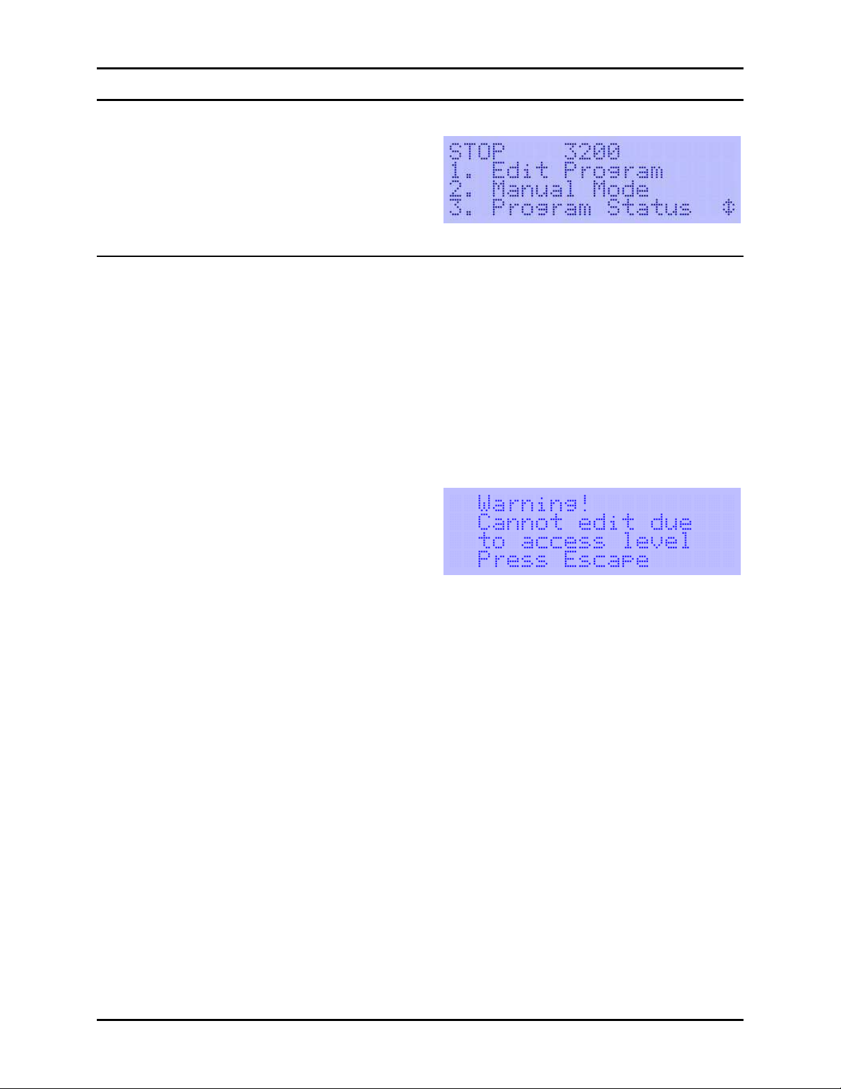
For most 200 operations you start from the startup main screen (shown above) and use function keys to
access other screens and functions. To return to the startup main screen from any other screen, press the
ESC key repeatedly until the main screen is displayed.
•To display the cause of the last chamber stop, press STOP. OTE: Pressing STOP while a program is
running will stop the program.
•To turn the chamber light(s) on or off from any screen, press the ESC (LIGHT) function key and hold
for one second.
•If you try to access a function that is not available
at the current access level, this screen will appear:
For more information on access levels, see
“Changing the access level or password” in Section
2 of this manual.

3200 Programmer/Controller Operator Manual Getting Starte
Thermotron In ustries This generic manual is not inten e to be use to operate your equipment. 1-3
3200 basic functions
The following sections provide brief descriptions of some of the 200 functions.
Control channels
Control channels receive inputs from thermocouples and/or other sensing devices used to monitor the
environmental conditions inside the chamber’s test space. The 200 adjusts its control outputs based on
those inputs.
•Typically, channel 1 uses a thermocouple mounted in the chamber airflow to sense air temperature. Its
outputs control the heating and cooling systems.
•Typically, channel 2 uses a solid-state humidity sensor to monitor chamber humidity. The reading from
the sensor is used together with the reading from the channel 1 thermocouple to calculate chamber
humidity. The channel 2 outputs control the humidity system’s steam generator and dehumidify coil.
•Channel , if available, can sense temperature or linear inputs. These channels commonly are
configured for such options as product temperature control or altitude.
•Channels 5 through 8 can be programmed at the factory as constant control channels. Each channel
can be set at the factory to sense either temperature or linear inputs.
Chamber con itioning system signals
The chamber conditioning signals are used by the controller to operate chamber systems such as heating,
cooling, and humidity. These signals are dedicated to the system and are internally programmed.
•The system, refrigeration, and humidity enable outputs allow their respective systems to turn on.
•The heat and cool outputs control their systems. For example, the channel 1 cool output normally
operates the solenoids that regulate the flow of refrigerant into the chamber’s evaporator coil.
•The auxiliary cool output operates any auxiliary cooling system, such as liquid nitrogen (LN
2
) or carbon
dioxide (CO
2
).
Alarm output signals
The alarm output transistor-transistor logic (TTL) signals indicate when the chamber temperature or
humidity exceeds the programmed limits. Two types of alarms are available for each channel:
•Deviation alarms are activated when the chamber temperature, humidity, or other process variable is
outside the channel’s deviation alarm band. A deviation alarm band restricts how far the process
variable can be from set point. For example, a deviation alarm band of 5°C activates the alarm output
if the chamber temperature is more than 5°C from set point.
Deviation alarms can be set for each manual mode test or program interval. For more information, see
“Running in manual mode” below, or Section later in this manual.
•Process alarms are activated when the chamber temperature, humidity, or other process variable is
outside the process limits. The process alarm settings restrict the high and low limits of a test. A
process alarm stops the programmer/controller. For example, if the high process alarm limit is +125°C,
the alarm is activated if the temperature equals or exceeds +125°C.
Process alarms are a configuration setting that can be adjusted only in setup mode. For more
information, see Section 2 later in this manual.

Getting Starte 3200 Programmer/Controller Operator Manual
1-2 This generic manual is not inten e to be use to operate your equipment. Thermotron In ustries
Auxiliary outputs
Auxiliary outputs provide programmable TTL level outputs. There can be up to two groups of eight
auxiliary outputs. These outputs are programmed on and off during each program interval or during
manual mode operation. These outputs normally are used to program systems on and off. For information
on your chamber’s auxiliary outputs, see your chamber manual.
Running in manual mo e
Manual mode allows you to operate the 200 controller functions. Manual mode operates the chamber
using set point settings. You can enter manual mode when the system is in stop mode.
Manual mo e
1. From the main screen select option 2. Manual
Mode. The manual mode screen will appear:
2. Use the up and down arrow keys to cycle through the following screens.
. The following list describes the manual mode values displayed:
•Set Point: Enter the desired value for each active channel. When the ramp rate is not zero, the set
point will change toward this new value at the selected rate.
•Aux Grp1 and Aux Grp2 (auxiliary groups 1 and 2): Enter the numbers of the auxiliary relays
you want to activate. Auxiliaries are active only when the 200 is running. For more information on
auxiliary relays, see “Auxiliary outputs” earlier in this section.

3200 Programmer/Controller Operator Manual Getting Starte
Thermotron In ustries This generic manual is not inten e to be use to operate your equipment. 1-5
•Hum (humidity): Enables the optional humidity system. OTE: Humidity is disabled if product
temperature control (PTC) is enabled.
•PTC (product temperature control): Enables the optional PTC control method. OTE: PTC is
disabled if humidity is enabled.
•Control Parameters: For more information on parameter groups, see “Adjusting standard control
parameters” or “Adjusting PTC control parameters” in Section 2 of this manual.
•Throttle: Positive values indicate heating or humidifying; negative values indicate cooling or
dehumidifying.
•Deviation: Enter the value for how far you will allow the temperature or other process variable to
be from set point. The deviation setting will be monitored and the deviation alarm will be
activated if the value is exceeded. Enter a positive number only; the 200 will monitor both
positive and negative deviations.
4. To start running in manual mode using the settings entered above, press RU .
5. To stop manual mode operation, press STOP.

Getting Starte 3200 Programmer/Controller Operator Manual
1-2 This generic manual is not inten e to be use to operate your equipment. Thermotron In ustries
Running a program
The programmer function operates the 200 using programs. Each program consists of a group of
intervals. In each interval the controller cycles the chamber toward a final temperature and/or other
process variable in a specified amount of time. Once the interval is completed, the 200 either transitions
to the next interval or loops back to an earlier interval.
Once a program is entered into memory it can be run immediately. To create a program, see Section of
this manual.
Program mo e
1. From any screen, press RU . ( OTE: The run
program screen will not appear when in program
edit mode or while a program is running.) The run
program screen will appear:
2. Select option 1 for program 1, interval 1. OTE: To
create a program, see Section of this manual.
. Select a starting interval. Then press the right
arrow key to run the selected program.
OTE: The start interval screen will only appear
when there is more than one interval created.
4. The 200 will enter run program mode and the
chamber status screen will appear:
For more information on the chamber status
screen, see “Chamber Status” later in this section.
5. To suspend the interval at its current settings,
press HOLD. The 200 will enter hold program
mode. From the top level menu, pressing the run
key, while RU P (run program) is displayed in the
top left corner, will display the message HOLD.
OTE: In hold program mode the 200 will maintain the chamber test space at the last set point.
6. To enter temporary values into the current interval, use the numeric keypad to enter a new value. For
additional information, go to step 4 of “Edit from hold” later in this section.
7. To resume running a suspended test, press RU .
8. To stop a running test, press STOP.
Table of contents
Other Thermotron Controllers manuals


Popular Controllers manuals by other brands

Digiplex
Digiplex DGP-848 Programming guide

YASKAWA
YASKAWA SGM series user manual

Sinope
Sinope Calypso RM3500ZB installation guide

Isimet
Isimet DLA Series Style 2 Installation, Operations, Start-up and Maintenance Instructions

LSIS
LSIS sv-ip5a user manual

Rockwell Automation
Rockwell Automation 1769-L31 installation instructions


