Thies CLIMA 5.4041 1.00 Series User manual

Precipitation Transmitter
Weighing scale principle
Instruction for Use
5.4041.x1.00x
Dok. No. 021857/01/21
T H E W O R L D O F W E A T H E R D A T A

© Adolf Thies GmbH & Co. KG · Hauptstraße 76 · 37083 Göttingen · Germany 021857/01/21
Tel. +49 551 79001-0 · Fax +49 551 79001-65 · [email protected]om ·www.thiesclima.com Seite 2 von 32
Safety Instructions
•Before operating with or at the device/product, read through the operating instructions.
This manual contains instructions which should be followed on mounting, start-up, and operation.
A non-observance might cause:
- failure of important functions
- endangerment of persons by electrical or mechanical effect
- damage to objects
•
Mounting, electrical connection and wiring of the device/product must be carried out only by a qualified
technician who is familiar with and observes the engineering regulations, provisions and standards
applicable in each case.
•Repairs and maintenance may only be carried out by trained staff or Adolf Thies GmbH & Co. KG.
Only components and spare parts supplied and/or recommended by Adolf Thies GmbH & Co. KG
should be used for repairs.
•Electrical devices/products must be mounted and wired only in a voltage-free state.
•Adolf Thies GmbH & Co KG guarantees proper functioning of the device/products provided that no
modifications have been made to the mechanics, electronics or software, and that the following points
are observed:
•All information, warnings and instructions for use included in these operating instructions must be
taken into account and observed as this is essential to ensure trouble-free operation and a safe
condition of the measuring system / device / product.
•The device / product is designed for a specific application as described in these operating instructions.
•The device / product should be operated with the accessories and consumables supplied and/or
recommended by Adolf Thies GmbH & Co KG .
•Recommendation: As it is possible that each measuring system / device / product may, under certain
conditions, and in rare cases, may also output erroneous measuring values, it is recommended using
redundant systems with plausibility checks for security-relevant applications.
Environment
•As a longstanding manufacturer of sensors Adolf Thies GmbH & Co KG is committed
to the objectives of environmental protection and is therefore willing to take back all
supplied products governed by the provisions of "ElektroG" (German Electrical and
Electronic Equipment Act) and to perform environmentally compatible disposal and
recycling. We are prepared to take back all Thies products concerned free of charge if
returned to Thies by our customers carriage-paid.
•Make sure you retain packaging for storage or transport of products. Should
packaging however no longer be required, please arrange for recycling as the
packaging materials are designed to be recycled.
Documentation
•© Copyright Adolf Thies GmbH & Co KG, Göttingen / Germany
•Although these operating instructions have been drawn up with due care, Adolf Thies GmbH & Co
KG can accept no liability whatsoever for any technical and typographical errors or omissions in this
document that might remain.
•We can accept no liability whatsoever for any losses arising from the information contained in this
document.
•Subject to modification in terms of content.
•The device / product should not be passed on without the/these operating instructions.

© Adolf Thies GmbH & Co. KG · Hauptstraße 76 · 37083 Göttingen · Germany 021857/01/21
Tel. +49 551 79001-0 · Fax +49 551 79001-65 · [email protected]om ·www.thiesclima.com Seite 3 von 32
Table of Contents
1Available Models............................................................................................................. 4
2Application...................................................................................................................... 5
3Construction and Mode of Operation............................................................................... 6
3.1 Measured Values and Electrical Output.....................................................................7
3.2 Heating......................................................................................................................8
4Recommendations Side Selection / Standard Installation ............................................... 8
5Installation....................................................................................................................... 9
5.1 Mechanical Mounting.................................................................................................9
5.2 Electrical Mounting..................................................................................................15
5.3 Plug Mounting .........................................................................................................15
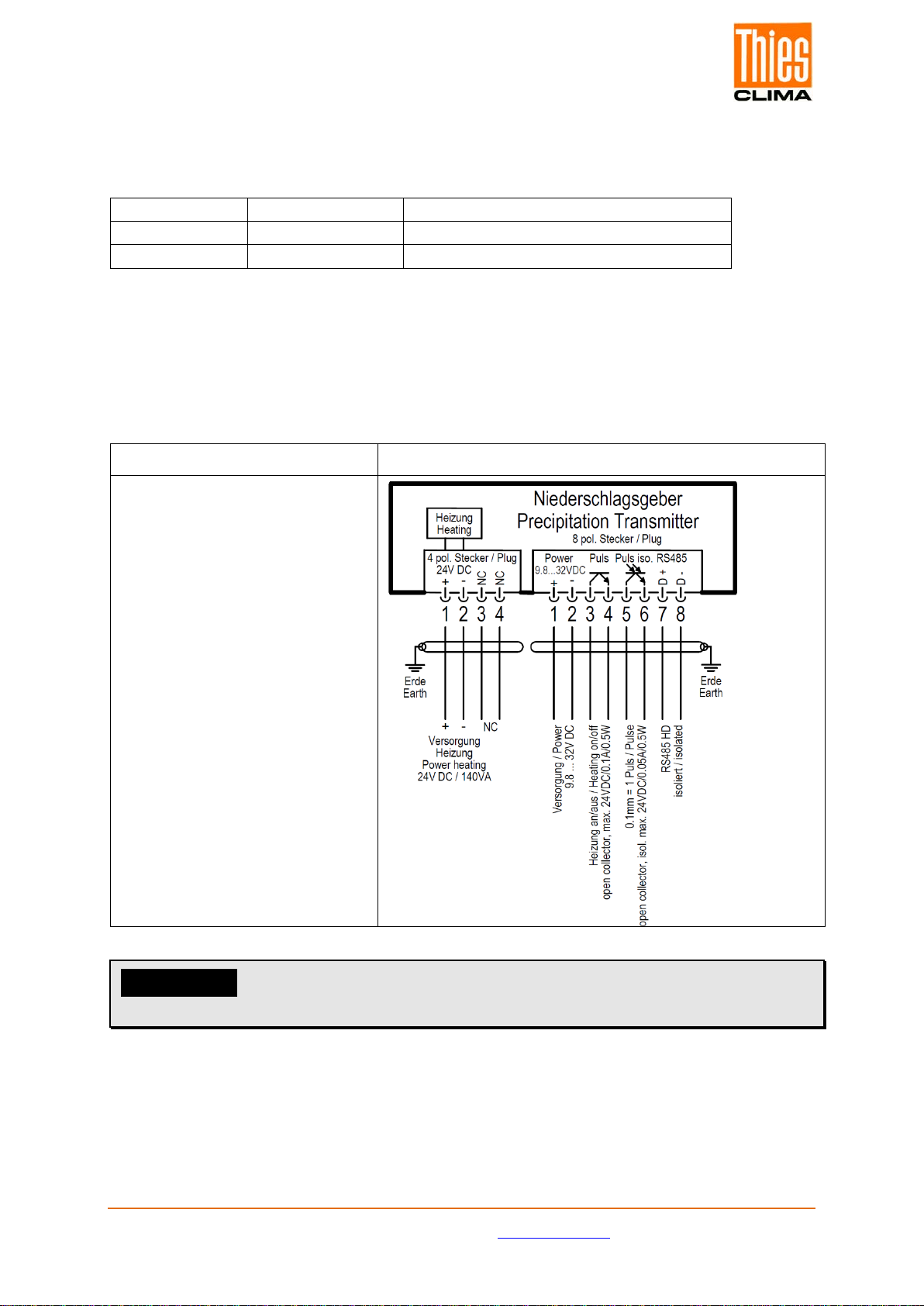
5.4 Power Connection and Signal Transmission............................................................16
5.4.1 Connection Order..............................................................................................17
Connections have to be carried out in the following order:............................................17
5.5 System Start............................................................................................................17
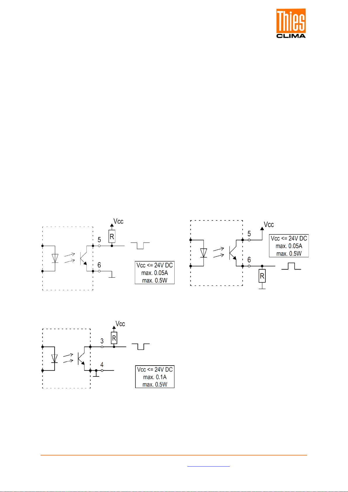
5.6 Interfaces ................................................................................................................18
5.6.1 Examples for the Connection to the Optocoupler ..............................................18
5.7 Factory Setting ........................................................................................................19
6Serial Communication....................................................................................................19
6.1 RS485-Interface......................................................................................................19
6.2 ASCII-Protocol.........................................................................................................19
6.2.1 Overview over Commands................................................................................21
6.2.1.1 Command a................................................................................................21
6.2.1.2 Command e................................................................................................21
6.2.1.3 Command i.................................................................................................22
6.2.1.4 Command m...............................................................................................22
6.3 Command Interpreter MODBUS-RTU......................................................................22
6.3.1 Measured Values (Input Register).....................................................................23
6.3.2 Configuration Parameters .................................................................................23
6.3.3 Mapping Register Modbus ................................................................................24
6.3.4Sensor Status (error) Explanation.....................................................................24
6.3.5 Quantity of Precipitation....................................................................................24
6.4 Pulse Output............................................................................................................25
7Maintenance, Checks and Troubleshooting ...................................................................25
8Technical Data...............................................................................................................27
9Accessories (optional)....................................................................................................28
10 Dimension Diagram .......................................................................................................29
11 EC-Declaration of Conformity ........................................................................................30
List of Figures
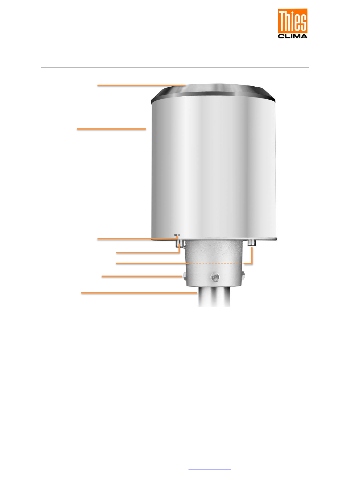
Figure 1: Construction............................................................................................................6
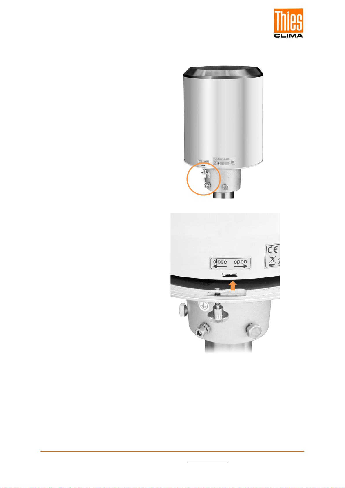
Figure 2: Open the device....................................................................................................10
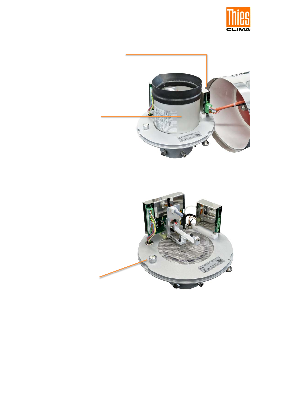
Figure 3: Inner parts and protective cylinder.........................................................................11
Figure 4: Installation of the collection vessel.........................................................................12
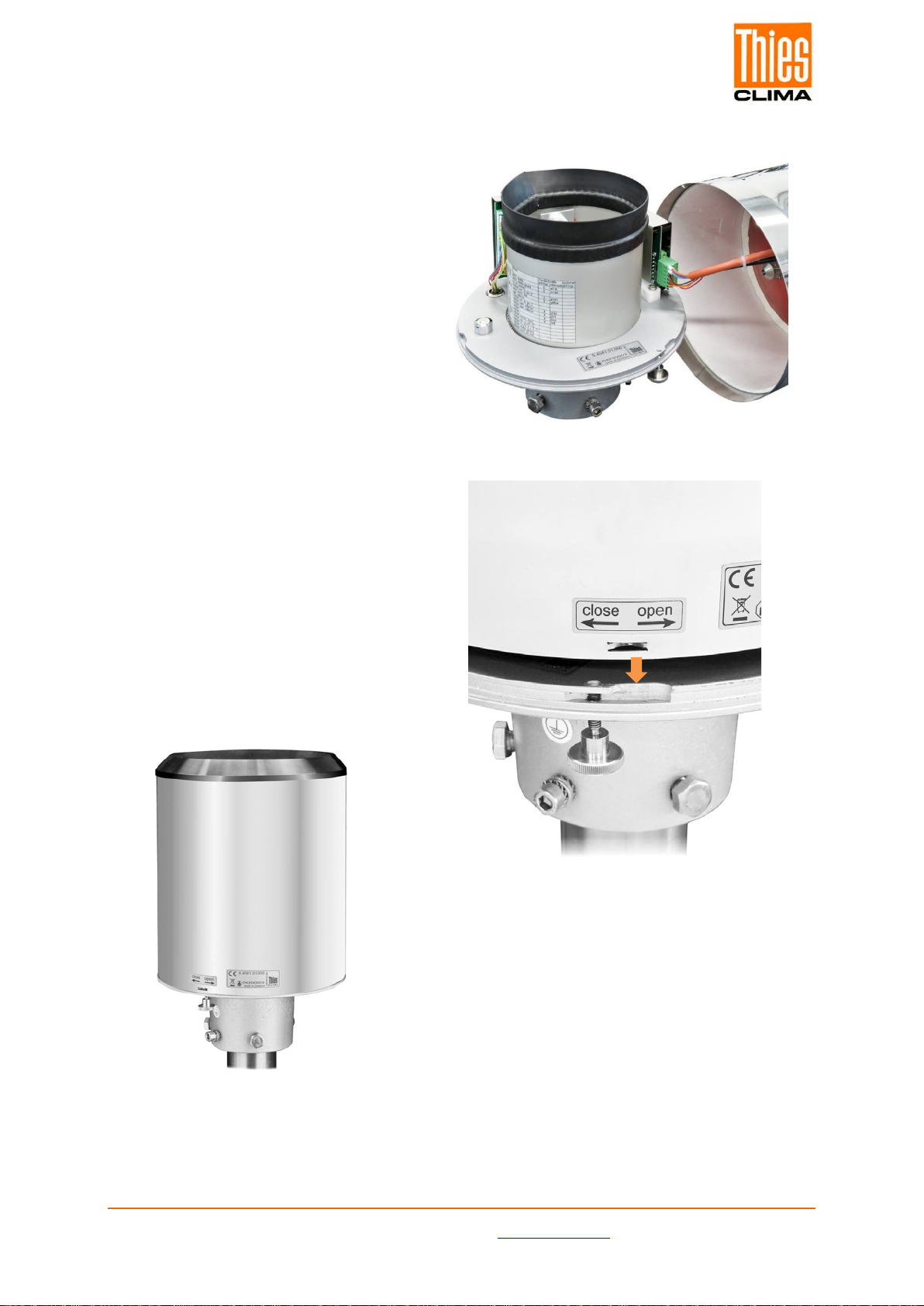
Figure 5: Re-assembly of the device ....................................................................................13
Figure 6: Dirt trap .................................................................................................................14
Figure 7: Examples for the Connection to the Optocoupler...................................................18
Figure 8: Dimension Diagram...............................................................................................29

© Adolf Thies GmbH & Co. KG · Hauptstraße 76 · 37083 Göttingen · Germany 021857/01/21
Tel. +49 551 79001-0 · Fax +49 551 79001-65 · [email protected]om ·www.thiesclima.com Seite 4 von 32
1 Available Models
Order no.
Heating
Power
supply
Heating
supply
Connection
type
Signal output
5.4041.01.000
Yes
9,8 … 32VDC
24VDC /
140 W
Plug
RS485 ASCII-
Protocol,-,
PULSE OUTPUT
5.4041.01.001
Yes
9,8 … 32VDC
24VDC /
140 W
Plug
RS485
MODBUS RTU,
PULSE OUTPUT
5.4041.11.000
No
9,8 … 32VDC
-
Plug
RS485 ASCII-
Protocol,-,
PULSE OUTPUT
5.4041.11.001
No
9,8 … 32VDC
-
Plug
RS485
MODBUS RTU,
PULSE OUTPUT
Scope of Supply:
- Precipitation transmitter, collection vessel included
- Operating instructions

© Adolf Thies GmbH & Co. KG · Hauptstraße 76 · 37083 Göttingen · Germany 021857/01/21
Tel. +49 551 79001-0 · Fax +49 551 79001-65 · [email protected]om ·www.thiesclima.com Seite 5 von 32
2 Application
The device combines cutting-edge weighing technology in a very small space with a self-
emptying collection vessel. The system provides excellent resolution and high precision.
Even minute drops will be measured.
The weighing precipitation transmitter is suited for use in meteorological and hydrological
monitoring networks as well as applications in the area of environmental monitoring.
Modbus RTU-interface facilitates installation of the sensor and its integration into networks.
The device is WMO-compliant and is equipped with interfaces which are compatible with
sensors with tipping bucket balances and other weighing systems. Other features are the
compact, robust design, a very low weight, stainless steel housing, weather resistance and
longevity. High connectivity is ensured by multiple interfaces as well as easy installation and
maintenance.
Scope of application:
•Meteorology
•Climatology
•Hydrology
•Industry
•Environmental monitoring

© Adolf Thies GmbH & Co. KG · Hauptstraße 76 · 37083 Göttingen · Germany 021857/01/21
Tel. +49 551 79001-0 · Fax +49 551 79001-65 · [email protected]om ·www.thiesclima.com Seite 6 von 32
Figure 1: Construction
3 Construction and Mode of Operation
Measuring edge
Housing
Locking screw
Connection for sensor
Connection for heating
Fastening screw
Stand pipe
The precipitation transmitter measures the quantity and intensity of precipitations. The
precipitation transmitter combines cutting-edge technology with a self-emptying collection
vessel. This allows the device to reach high resolution and precision with a significantly
smaller overall volume. The precipitation transmitter thus features higher resolution and
precision than traditional precipitation transmitters working on the basis of the tipping bucket
balance principle, as it does not require a catch tank.
The main sensor is a high-precision weighing cell with overload protection. If required, its
temperature coefficient is determined with a temperature probe inside the housing. The
pulses of the Reed contact triggered by the tipping movements of the collection vessel are
used for the correction of errors in case of high precipitation intensities. In addition, the self-
emptying mechanism of the collection vessel permits weighing without interruptions.

© Adolf Thies GmbH & Co. KG · Hauptstraße 76 · 37083 Göttingen · Germany 021857/01/21
Tel. +49 551 79001-0 · Fax +49 551 79001-65 · [email protected]om ·www.thiesclima.com Seite 7 von 32
3.1 Measured Values and Electrical Output
The precipitation transmitter measures/calculates the following values:
Quantity of precipitation (pulse)
The precipitation quantity is issued in real time with a maximum resolution of 0.01mm
via the pulse output.
Intensity of precipitation of the last minute (RS485-interface)
The precipitation transmitter performs six measurements per minute and adds
these values up in a moving sum. This means that every new measured value is
added to the previous five measured values, resulting in the new intensity value
of the last minute.
Intensity of precipitation since the last retrieval (RS485-interface)
The difference in quantity since the last retrieval is divided by the time that passed
since the last retrieval. If the last retrieval took place less than 30s ago, the
intensity of the last minute is used automatically.
Quantity of precipitation since the last retrieval (RS485-interface)
Difference of quantities between the new and the last retrieval.
Minimum precipitation intensity of the last X minutes (RS485-interface)
For X minutes, the value for the intensity of the last minute is compared every minute
with the one of the previous minute and the lower value of the two is retained.
Maximum precipitation intensity of the last X minutes (RS485-interface)
For X minutes, the value for the intensity of the last minute is compared every minute
with the one of the previous minute and the higher value of the two is retained.
Average intensity of the last X minutes (RS485-interface)
Counts the precipitation quantity over X minutes in steps of 0.01mm and divides the
result by the X minutes.
Variance (RS485-interface) variance of measured values over 4s
The two pulse outputs can be matched so that they output the quantity of precipitation with
a resolution of 0,01…1mm and closing times of 10...500ms.
Alternatively, they can be configurated in such a manner that they output the status of the
heating (heating ON/OFF) or the precipitation status (YES/NO).
The Rs485-interface at the precipitation transmitter can be operated in ASCII- or Modbus-
protocol. See chapter 1. Available Models.

© Adolf Thies GmbH & Co. KG · Hauptstraße 76 · 37083 Göttingen · Germany 021857/01/21
Tel. +49 551 79001-0 · Fax +49 551 79001-65 · [email protected]om ·www.thiesclima.com Seite 8 von 32
3.2 Heating
For applications in regions with seasonally or permanently low temperatures, the
precipitation transmitter is available in a heated version. The internal heating is divided into
two parts: a funnel heating along the inner surface of the catch funnel of the precipitation
transmitter melts solid precipitations and the outlet heating below the protection grille and
the collection vessel prevents complete freezing of the outlet. With operating temperatures
of -40 ... 70°C, the target temperature of the funnel surface of the heated precipitation
transmitter is 2 C. The operability is checked continuously and can be queried via the
Rs485-interface or the pulse output.
In the factory default setting, the heating is switched on (measuring device with heating).
The heating is supplied with power via a separate power supply line. Funnel heating and
outlet heating can get very hot. Danger of burns! Always switch off/separate the power
supply before opening the device.
4 Recommendations Side Selection
To minimize water splashing up, it is recommended to avoid installation sites with a hard
surface like concrete and to install the precipitation transmitter on grass or other soft
surfaces instead.
In general, the sensor should not be placed on roofs or slopes.
According to WMO-recommendations, precipitation gauges have to be installed at a distance
of no less than four times the height of the next obstacle. If this is not possible, care has to
be taken to maintain an elevation angle of less than 45° towards surrounding plants,
buildings etc.
The measuring device has to be set up in such a manner that the catch is aligned
horizontally and that its distance from the floor is 1m. When snow is to be regularly expected
in the area of the measuring device, this distance should be increased accordingly.
Please note:
Precipitation gauges have to be installed for vibration-free operation.

© Adolf Thies GmbH & Co. KG · Hauptstraße 76 · 37083 Göttingen · Germany 021857/01/21
Tel. +49 551 79001-0 · Fax +49 551 79001-65 · [email protected]om ·www.thiesclima.com Seite 9 von 32
5 Installation
Please note:
Electrical work has to be carried out by skilled staff.
The device may only be opened in dry surroundings.
Avoid damaging the exposed electronic parts. Open the device only when
power supply is off.
5.1 Mechanical Mounting
Please note:
The enclosed tipping bucket balance may only be operated with this
precipitation transmitter. Avoid damaging the upper funnel edge.
Required tools
- jaw wrench (13mm)
- Allen wrench (6mm)
- slotted screwdriver (approx. 2.5 blade width)
1. Place the precipitation transmitter on top of a tube or mast with an external diameter of
60mm. Use the jaw wrench (13mm) to pre-tighten the screws at the base evenly. Tighten
them completely only when step 17 has been completed.
2. To improve operational safety, we recommend to ground the sensor with the aid of the
integrated earth screw. This can be performed by means of a suitable earthing cable and
an earth bolt (not included in the scope of supply) or through a connection to an existing
grounding system.

© Adolf Thies GmbH & Co. KG · Hauptstraße 76 · 37083 Göttingen · Germany 021857/01/21
Tel. +49 551 79001-0 · Fax +49 551 79001-65 · [email protected]om ·www.thiesclima.com Seite 10 von 32
3. Open the device.
4. Unscrew the thumb screw at the
bottom.
5. Grasp upper edge of the funnel
and at the mast holder and turn the
upper part counter-clockwise (open
).
6. Lift the housing off carefully,
watch out for the clamping connector
of the heating.
Figure 2: Open the device

© Adolf Thies GmbH & Co. KG · Hauptstraße 76 · 37083 Göttingen · Germany 021857/01/21
Tel. +49 551 79001-0 · Fax +49 551 79001-65 · [email protected]om ·www.thiesclima.com Seite 11 von 32
7. Remove the clamping connector
of the heating.
8. Put the housing aside.
9. Lift off the internal protective
cylinder.
Internal protective cylinder
Inner parts without collection
vessel
Spirit level
Figure 3: Inner parts and protective cylinder

© Adolf Thies GmbH & Co. KG · Hauptstraße 76 · 37083 Göttingen · Germany 021857/01/21
Tel. +49 551 79001-0 · Fax +49 551 79001-65 · [email protected]om ·www.thiesclima.com Seite 12 von 32
Installation of the collection
vessel
13. Unpack the collection vessel
14. Push the collection vessel with
the side where the magnet is placed
(red marking) towards the Reed
contact (red marking), against the
bearing spring.
15. Insert the other side of the axle
into the other side of the bearing.
16. Make sure that the collection
vessel tips perfectly.
17. Level the device with the aid of
the bubble level (see figure 3),
tightening the hexagon bolts at the
base evenly.
Figure 4: Installation of the collection vessel

© Adolf Thies GmbH & Co. KG · Hauptstraße 76 · 37083 Göttingen · Germany 021857/01/21
Tel. +49 551 79001-0 · Fax +49 551 79001-65 · [email protected]om ·www.thiesclima.com Seite 13 von 32
Re-assembly of the device
19. Re-insert the internal protective
cylinder carefully.
20. Connect the clamping connector
of the heating.
21. Set the housing back on the
base plate – place embossed parts
into the recesses.
22. Push the housing downwards
and then turn it clockwise into the
direction „close“ .
23. Fasten the housing with the
thumb screw.
To protect the collection vessel against contamination, the dirt trap has to be installed in
the funnel.
Figure 5: Re-assembly of the device

© Adolf Thies GmbH & Co. KG · Hauptstraße 76 · 37083 Göttingen · Germany 021857/01/21
Tel. +49 551 79001-0 · Fax +49 551 79001-65 · [email protected]om ·www.thiesclima.com Seite 14 von 32
24. Insert the enclosed dirt trap into the
centre of the funnel. The cap on the dirt trap
also serves as protection against coarse
dirt. The dirt trap stands loosely in the
centre of the funnel.
Figure 6: Dirt trap

© Adolf Thies GmbH & Co. KG · Hauptstraße 76 · 37083 Göttingen · Germany 021857/01/21
Tel. +49 551 79001-0 · Fax +49 551 79001-65 · [email protected]om ·www.thiesclima.com Seite 15 von 32
5.2 Electrical Mounting
Type of cable
Plug
Cable specification
Signal cable
8-wire – 214127
PUR, shielded, 8 x 0.25mm² (Ø 6mm)
Heating cable
4-Wire – 214135
PUR, 4x1.5mm² (Ø 8,4mm)
To avoid malfunctions, all wires which are not used have to be connected to an unused
terminal or they have to be insulated. You can obtain configurated cables from us optional.
See 9. Accessories.
5.3 Plug Mounting
Order no.
Connection diagram
5.4041.01.00x
5.4041.11.00X without heating;
meaning that heating plug and heating
cable are not required.
Please note:
Observe connection order described in point 5.4.1.

© Adolf Thies GmbH & Co. KG · Hauptstraße 76 · 37083 Göttingen · Germany 021857/01/21
Tel. +49 551 79001-0 · Fax +49 551 79001-65 · [email protected]om ·www.thiesclima.com Seite 16 von 32
Signalling
cable plug 8-
pin-214127
View, mating plug
Heating cable
plug 4-pin –
214135
View, mating plug
5.4 Power Connection and Signal Transmission
For the connection of the measuring system to a data acquisition device as e. g. the data
logger, a connection cable with an M12-plug is required. A separate power cable is required
for the power supply to the heating. The cables have to be connected as shown in the
connection diagram.

© Adolf Thies GmbH & Co. KG · Hauptstraße 76 · 37083 Göttingen · Germany 021857/01/21
Tel. +49 551 79001-0 · Fax +49 551 79001-65 · [email protected]om ·www.thiesclima.com Seite 17 von 32
5.4.1 Connection Order
Connections have to be carried out in the following order:
1. Connect external power connection of heating.
2. Connect sensor cable.
The maximum possible distance between measuring device and data recording device
depends on the interface used. The standards applicable to the values obtained with RS485
(1000 m) apply.
Cable cross-section [mm²]
1.5
Length of cable [m] Heating output [VA] Line loss [VA]
1.0 138.5 1.5
1.5 137.7 2.3
5.0 132.6 7.4
10.0 125.8 14.2
This table provides an overview over output losses with different cable lengths. The output
loss has to be taken into account when considering the energy balance.
5.5 System Start
The device starts automatically as soon as the sensor cable is connected. After approx.
15s, the device is ready to operate, starts to measure and transmits data in accordance
with the device configuration.
Overview: Status LED (green) on the motherboard
System Start Uninterrupted lighting of LED for approx. 3 seconds
Operating Fast flashing of LED

© Adolf Thies GmbH & Co. KG · Hauptstraße 76 · 37083 Göttingen · Germany 021857/01/21
Tel. +49 551 79001-0 · Fax +49 551 79001-65 · [email protected]om ·www.thiesclima.com Seite 18 von 32
5.6 Interfaces
The precipitation transmitter is equipped with the following interfaces:
◦Serial interface:
◦RS485, (half duplex), ASCII- and MODBUS RTU-protocol,
◦Pulse output 1 precipitation:
◦1 galvanically isolated open collector output
◦Precipitation output according to factory-default resolution and closing time; on
request, the factory setting can be modified to customer specifications.
◦Pulse output 2 heating:
◦1 uninsulated open collector output
◦Heating ON/OFF
5.6.1 Examples for the Connection to the Optocoupler
Pulse output 1 precipitation
Pulse output 2 heating
Figure 7: Examples for the Connection to the Optocoupler

© Adolf Thies GmbH & Co. KG · Hauptstraße 76 · 37083 Göttingen · Germany 021857/01/21
Tel. +49 551 79001-0 · Fax +49 551 79001-65 · [email protected]om ·www.thiesclima.com Seite 19 von 32
5.7 Factory Setting
Relating to connection diagram (5.2. Electrical assembly), factory default settings.
1) Uninsulated pulse output as status output
2) Galvanically isolated pulse output
6 Serial Communication
6.1 RS485-Interface
To enable communication via the RS-485-interface, the precipitation transmitter is equipped
with a command interpreter which supports the following 2 modes:
- ASCII
- MODBUS RTU
Interface setting:
Baud rate: 19200 Baud
Data bits: 8
Parity: none
Stop bits: 1
6.2 ASCII-Protocol
The measuring system is able to reply with the defined ASCII-protocol via the RS485-
interface. In this protocol, the sensor may be addressed every 10s, while it is recommended
to work with intervals of 60s.
Basically, a command is set up as follows:
•<STX><Command><CR><LF>
<STX> Start protocol (Start text)
<Command> Command containing 1 character (please refer to list of commands)
<CR> Carriage Return (13dec; 0x0D)
<LF> Line Feed (10dec; 0x0A)
Order no.
Heating1
Resolution2
Closing
time
2
Protocol
Modbus ID
Baud-
rate
Frame
format
5.4041.01.000 A
0.1mm 300ms
ASCII
1 19200Bd 8E1
5.4041.01.001
MODBUS
RTU
5.4041.11.000 Off ASCII
5.4041.11.001
MODBUS
RTU

© Adolf Thies GmbH & Co. KG · Hauptstraße 76 · 37083 Göttingen · Germany 021857/01/21
Tel. +49 551 79001-0 · Fax +49 551 79001-65 · [email protected]om ·www.thiesclima.com Seite 20 von 32
Addressing is not possible in case of the precipitation transmitter, for this reason, it may not
be used in the bus system. It may only be used as single measuring system. (Bus operation
s.h. MODBUS-RTU).
When a command containing a parameter is transmitted, the parameter is checked. When it
is valid, the parameter is saved and acknowledged in the “echo telegram”. When it is invalid,
the parameter is ignored and the value set in the “echo telegram” is issued.
Example:
<STX>a<CR><LF> measured value query
0.059;0.073;0.031<CR><LF> reply
0.059 = Average intensity in mm/min
0.073 = Max. intensity in mm/min
0.031 = Min. intensity in mm/min
<STX>m<CR><LF> measured value query
1.120;67.200;1.120;67.200;11.200;25.400;0;12<CR><LF> reply
1.120 = Intensity in mm/min
67.200 = Intensity in mm/h
1.120 = Average intensity since last retrieval in mm/min
67.200 = Average intensity since last retrieval in mm/min
11.200 = Quantity since last retrieval in mm
25.400= Total precipitation volume* since system start in mm
0; = Status of heating (1 = ON, 0 = OFF)
12 = Temperature in °C
The measured values are separated by semicolon.
This manual suits for next models
4
Table of contents
Other Thies CLIMA Transmitter manuals

Thies CLIMA
Thies CLIMA 4.3515.5 Series User manual

Thies CLIMA
Thies CLIMA 4.3351.00.000 User manual

Thies CLIMA
Thies CLIMA 5.4103.10.000 User manual

Thies CLIMA
Thies CLIMA 4.3120.22.012 User manual

Thies CLIMA
Thies CLIMA 4.3151.x0.400 Series User manual

Thies CLIMA
Thies CLIMA 4.3515.30.000 User manual

Thies CLIMA
Thies CLIMA Modbus User manual

Thies CLIMA
Thies CLIMA 4.3519 Series User manual