Thies CLIMA Modbus User manual
Wind Direction Transmitter
>>First Class<<
Instruction for Use
4.3151.xx.401
- Device with digital output (MODBUS RTU), RS 485
- Wind velocity signal acquisition
Dok. No. 021887/12/20
T H E W O R L D O F W E A T H E R D A T A
© Adolf Thies GmbH & Co. KG · Hauptstraße 76 · 37083 Göttingen · Germany 021887/12/20
Phone +49 551 79001-0 · Fax +49 551 79001-65 · inf[email protected] · www.thiesclima.com 2 - 34
Safety Instructions
•Before operating with or at the device/product, read through the operating instructions.
This manual contains instructions which should be followed on mounting, start-up, and operation.
A non-observance might cause:
- failure of important functions
- endangerment of persons by electrical or mechanical effect
- damage to objects
•Mounting
, electrical connection and wiring of the device/product must be carried out only by a qualified
technician who is familiar with and observes the engineering regulations, provisions and standards ap-
plicable in each case.
•Repairs and maintenance may only be carried out by trained staff or Adolf Thies GmbH & Co. KG.
Only components and spare parts supplied and/or recommended by Adolf Thies GmbH & Co. KG
should be used for repairs.
•Electrical devices/products must be mounted and wired only in a voltage-free state.
•Adolf Thies GmbH & Co KG guarantees proper functioning of the device/products provided that no
modifications have been made to the mechanics, electronics or software, and that the following points
are observed:
•All information, warnings and instructions for use included in these operating instructions must be
taken into account and observed as this is essential to ensure trouble-free operation and a safe condi-
tion of the measuring system / device / product.
•The device / product is designed for a specific application as described in these operating instructions.
•The device / product should be operated with the accessories and consumables supplied and/or rec-
ommended by Adolf Thies GmbH & Co KG .
•Recommendation: As it is possible that each measuring system / device / product may, under certain
conditions, and in rare cases, may also output erroneous measuring values, it is recommended using
redundant systems with plausibility checks for security-relevant applications.
Environment
•As a longstanding manufacturer of sensors Adolf Thies GmbH & Co KG is committed
to the objectives of environmental protection and is therefore willing to take back all
supplied products governed by the provisions of "ElektroG" (German Electrical and
Electronic Equipment Act) and to perform environmentally compatible disposal and
recycling. We are prepared to take back all Thies products concerned free of charge if
returned to Thies by our customers carriage-paid.
•Make sure you retain packaging for storage or transport of products. Should packag-
ing however no longer be required, please arrange for recycling as the packaging ma-
terials are designed to be recycled.
Documentation
•© Copyright Adolf Thies GmbH & Co KG, Göttingen / Germany
•Although these operating instructions have been drawn up with due care, Adolf Thies GmbH & Co
KG can accept no liability whatsoever for any technical and typographical errors or omissions in this
document that might remain.
•We can accept no liability whatsoever for any losses arising from the information contained in this doc-
ument.
•Subject to modification in terms of content.
•The device / product should not be passed on without the/these operating instructions.

© Adolf Thies GmbH & Co. KG · Hauptstraße 76 · 37083 Göttingen · Germany 021887/12/20
Phone +49 551 79001-0 · Fax +49 551 79001-65 · inf[email protected] · www.thiesclima.com 3 - 34
Table of contents
1Available Models...........................................................................................................4
2Application....................................................................................................................4
3Mode of Operation........................................................................................................5
4Recommendation Site Selection / Standard Installation................................................6
5Installation ....................................................................................................................6
5.1 Wind Vane Mounting.................................................................................................7
5.2 Mechanical Mounting and Alignment.........................................................................8
5.3 Electrical Mounting..................................................................................................10
5.3.1 Cable ................................................................................................................10
5.3.2 Cable Shield......................................................................................................10
5.3.3 Plug and Cable Mounting..................................................................................12
6Connecting Diagram...................................................................................................13
6.1 Example Connection Diagram.................................................................................14
7Serial Interface (RS485) .............................................................................................15
8Placing into Operation ................................................................................................15
9Serial Communication.................................................................................................15
10 Commands and Description........................................................................................16
10.1 Command BR..........................................................................................................17
10.2 Command CI...........................................................................................................17
10.3 Command FB..........................................................................................................18
10.4 Command ID...........................................................................................................18
10.5 Command KY..........................................................................................................18
10.6 Command MI...........................................................................................................19
10.7 Command OR .........................................................................................................19
10.8 Command RD..........................................................................................................19
10.9 Command RS..........................................................................................................20
10.10 Command SF..........................................................................................................20
10.11 Command SN..........................................................................................................20
10.12 Command SV..........................................................................................................21
10.13 Command TR..........................................................................................................21
10.14 Command TT ..........................................................................................................21
11 Command Interpreter MODBUS RTU.........................................................................22
11.1 Messwerte (Input Register)......................................................................................23
11.2 Commands (Holding Register).................................................................................24
12 Data Telegram............................................................................................................25
12.1 Telegram 3..............................................................................................................25
12.2 Telegram 4..............................................................................................................25
12.3 Telegram 5..............................................................................................................26
13 Maintenance...............................................................................................................26
14 Technical Data............................................................................................................27
15 Dimensional Drawing..................................................................................................29
16 Accessories................................................................................................................30
17 EC-Declaration of Conformity .....................................................................................32

© Adolf Thies GmbH & Co. KG · Hauptstraße 76 · 37083 Göttingen · Germany 021887/12/20
Phone +49 551 79001-0 · Fax +49 551 79001-65 · inf[email protected] · www.thiesclima.com 4 - 34
Table overview
Table 1: Commands.............................................................................................................16
Table 2: MODBUS Frame ....................................................................................................22
Table 3: MODBUS Exceptions .............................................................................................22
Table 4: MODBUS Input Register.........................................................................................23
1 Available Models
*) see chapter 5.2 mechanical mounting and alignment or 15. dimensional drawing
2 Application
The wind direction transmitter serves for the detection of the horizontal wind direction in the
field of meteorology and the technology of environmental protection.
The measuring value is available in binary format on request as a serial data telegram via an
RS485 interface. The data telegram is able to operate, for e.g., wind displays, dataloggers,
process control systems.
The wind direction transmitter can also record the pulse signals from an anemometer and
can complete its serial data telegram by the parameter wind velocity.
Special characteristics:
•High level of measuring accuracy and resolution.
•High damping ratio at a small delay distance.
•Low starting threshold.
•Low current consumption (1,0mA @ 3,3 … 42V).
•Option for connecting an anemometer “First Class 4.335x.x0.000“.
•Data telegram additionally with wind velocity. (WV = 0,0462*f+0,21)
For wintertime use the wind direction transmitter (see chapter 1 models available) is optionally
equipped with an electronically regulated heating, which guarantees the smooth running of the
ball bearing, and prevents ice forming in the space between the external rotation parts.
Order - No.
Winddirection
Measuring range
Windvelocity
Input [Hz]
Interface /
Data output
Supply
Heating
South
bore*
4.3151.00.401
0 ... 360 ° 1082Hz
@ 50m/s
RS 485 /
Modbus RTU 3,3 … 42V DC
With Without
4.3151.01.401 With
4.3151.10.401 Without Without
4.3151.11.401 With

© Adolf Thies GmbH & Co. KG · Hauptstraße 76 · 37083 Göttingen · Germany 021887/12/20
Phone +49 551 79001-0 · Fax +49 551 79001-65 · inf[email protected] · www.thiesclima.com 5 - 34
3 Mode of Operation
Wind direction
The dynamic characteristics of the wind vane is achieved by the aluminum lightweight con-
struction. The co-action of wind vane and balance weight results in a high damping ratio with
small delay distance as excellent characteristic of the complete vane.
The axis of the wind vane is running in ball bearings and carries a diametrically magnetized
magnet at the inner end. The angle position of the axis is scanned contact-free by a mag-
netic angle sensor (TMR-Sensor, Tunnel Magneto Resistance) through the position of the
magnet field. As the sensor is operated in magnetic saturation, effects by external magnetic
fields can almost be eliminated. The connected electronics calculates the angle position of
the axis and provides the respective serial output signal.
Note:
The wind direction is recorded 4 times per second.
Acquisition of Wind Velocity
Additionally to the wind direction acquisition the wind direction transmitter offers the option of
supplying the wind velocity signal from the Wind transmitter First Class 4.335x.x0.000. The
wind velocity signal is acquired and analyzed and is available in the output register along
with the acquired wind direction.
The measured frequency is converted into the wind speed using the following straight line
equation
= 0,0462 ∗ + 0,21 :ℎ
:
With frequency of 0Hz the wind speed is set to 0m / s.
Note:
The wind speed (frequency) is recorded by means of a period duration measurement (inter-
nal reference clock: 4MHz).
General
An AC- or DC-voltage of 24V is intended for the separate supply of the optional heating. In all
probability, the heating guarantees a trouble-free function of the Wind Direction Transmitter
First Class even under extreme meteorological icing-conditions.
The outer parts of the instrument are made of corrosion-resistant anodized aluminum and
stainless steel. Highly effective labyrinth gaskets and O-rings protect the sensitive parts in-
side the instrument against humidity and dust.

© Adolf Thies GmbH & Co. KG · Hauptstraße 76 · 37083 Göttingen · Germany 021887/12/20
Phone +49 551 79001-0 · Fax +49 551 79001-65 · inf[email protected] · www.thiesclima.com 6 - 34
4 Recommendation Site Selection / Standard Installation
In general wind measurement instruments should be able to detect the wind conditions of a
large area. In order to obtain comparable values when determining the surface wind, meas-
urements should be taken at a height of 10 meters over an even area with no obstacles. An
area with no obstacles means that the distance between the wind direction transmitter and an
obstacle should be at least 10 times the height of the obstacle (s. VDI 3786 Part 2). If it is not
possible to fulfill this condition then the wind direction transmitter should be set up a height
where local obstacles do not influence the measured values to any significant extent (approx.
6 … 10m above the obstacle). The wind direction transmitter should be set up in the center of
flat roofs and not on the edge in order to avoid any preferential directions.
5 Installation
Attention:
Storing, mounting and operation under weather conditions is permissible only
in vertical position, as otherwise water can get into the instrument.
Remark:
When using fastening adapters (angle, traverses, etc.) please take a possible effect on the
measurements by turbulences into consideration.
Caution:
The device may only be supplied with a power supply of the "Class 2, limited
power”.
© Adolf Thies GmbH & Co. KG · Hauptstraße 76 · 37083 Göttingen · Germany 021887/12/20
Phone +49 551 79001-0 · Fax +49 551 79001-65 · inf[email protected] · www.thiesclima.com 7 - 34
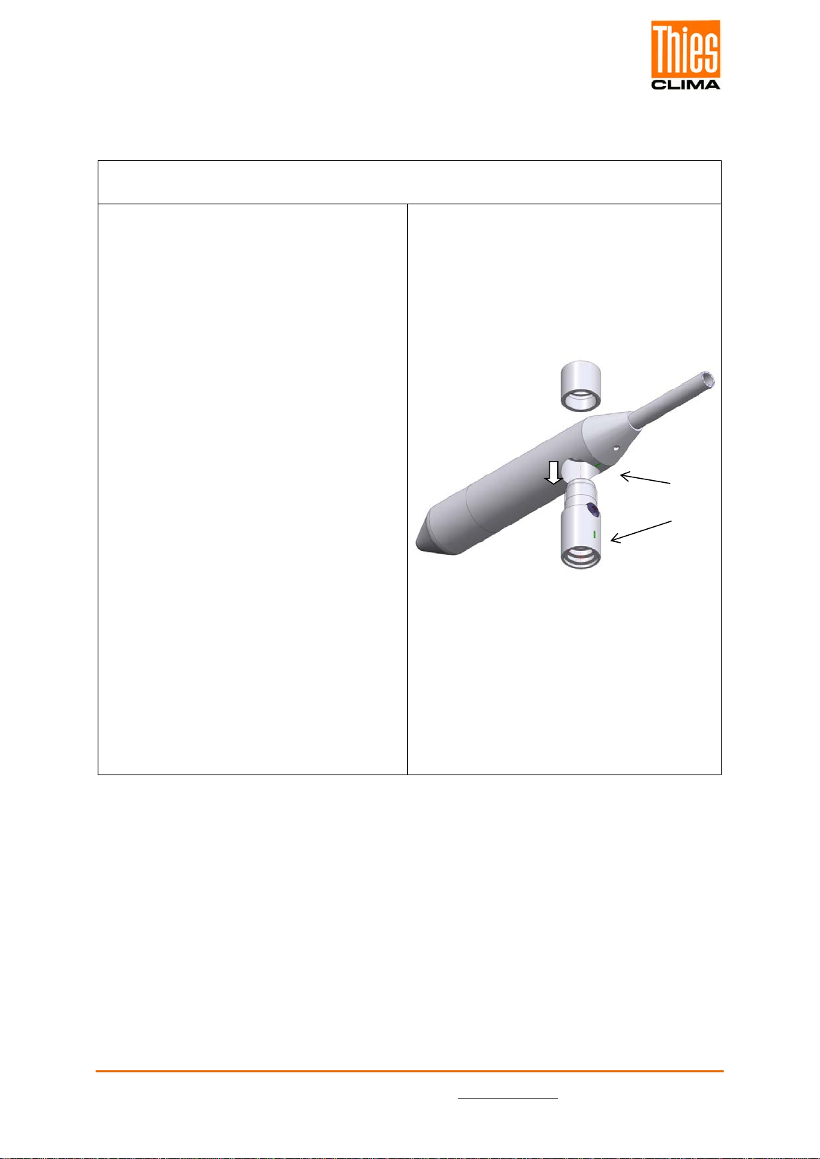
5.1 Wind Vane Mounting
Before the wind direction transmitter can be installed at its selected site, the wind vane
must be mounted on the housing.
Tool:
Not required.
Process
1. Remove wind transmitter shaft and
wind vane from the packing.
2. Remove capby left-hand rotation
of upper partof wind transmitter
shaft.
3. Put the wind vane onto the upper
part of the wind transmitter shaft.
Remark:
The longer part of the wind vane
blade must indicate upwards.
4. Keep hold of the wind vane by hand
to avoid twist movement, and turn
the upper part of the wind transmitter
shaft until the vane locks into the for-
cible control.
Remark:
The marking linesat the bottom of
wind vane counter weight, and at the
upper part of the wind transmitter
shaft, must be aligned.
5. Put the cap onto the thread, and
seize strongly by clockwise rotation
by hand ... ready

© Adolf Thies GmbH & Co. KG · Hauptstraße 76 · 37083 Göttingen · Germany 021887/12/20
Phone +49 551 79001-0 · Fax +49 551 79001-65 · inf[email protected] · www.thiesclima.com 8 - 34
5.2 Mechanical Mounting and Alignment
Remark:
The wiring must be prepared so far, that plug and cable have been pushed through instru-
ment carrier, mast, traverse etc., and can be connected to the wind direction transmitter at
the moment of the “Mechanical Mounting”, described in the following (please refer to
chapter 5.3.).
The wind direction transmitter must be mounted on an instrument carrier, which is suited for
the measurement. For dimensions of wind direction transmitter please refer to chapter 15
Dimension diagram.
Suitable instrument carriers are masts, tubes, traverses, arms, adapters, adapters of POM
for isolated mounting, which correspond to the mounting dimensions of the wind transmit-
ter, and to the static requirements.
The inner diameter of the instrument carrier should be ≥ 20mm based on plug- and cable
feed-through.
If the north alignment is carried out by compass, please consider the local declination
(= deviation of direction of the magnetic needle from the true north), and local magnetic in-
terferences (e.g. hardware, electric cable).
For alignment aid and for easy changing / replacement without readjustment:
With the help of the north-ring (accessory 509619):
The optional north ring part. no. 509619 can be used to mount the wind transmitter. The
north ring serves as an alignment aid and for easy changing / replacement without having
to re-adjustment of the north direction of wind direction indicators. The north ring uses the
north borehole of the mast holder for this. See chapter 15 Dimension diagram.
With the help of the south borehole:
The south borehole is used for alignment in the north / south direction. It serves as an
alignment aid and for easy changing / replacement without readjustment. For north orienta-
tion using the south hole, you have to construct your mounting mast specifically. See chap-
ter 15 Dimension diagram.
When aligning the wind direction transmitter on a moving object (e.g. vehicle, wind wheel,
ship etc) please consider that the “north point” to be determined, might possibly be located
on the object.
© Adolf Thies GmbH & Co. KG · Hauptstraße 76 · 37083 Göttingen · Germany 021887/12/20
Phone +49 551 79001-0 · Fax +49 551 79001-65 · inf[email protected] · www.thiesclima.com 9 - 34
Tools:
Hexagon socket wrench size 3
(Allen key).
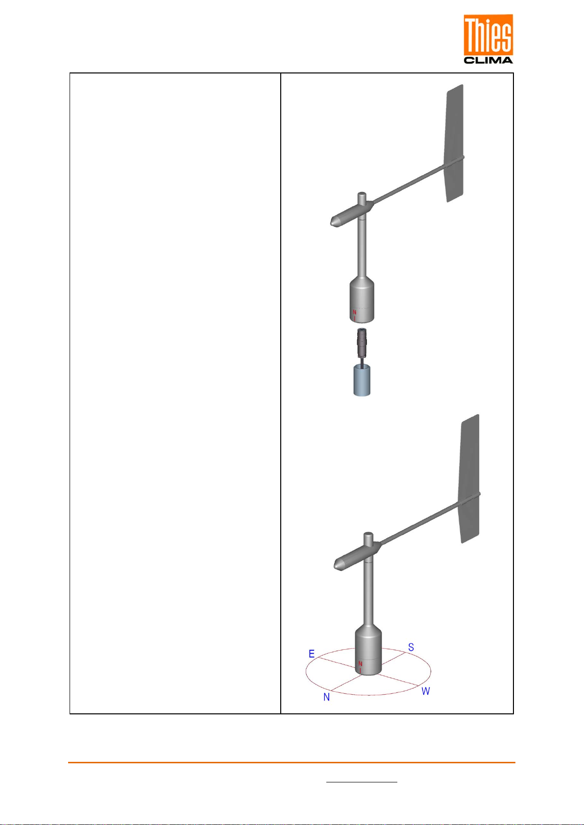
Procedure:
1. Push cable/ plug connector of the
wind direction transmitter through
the borehole of the mast, tube, arm
etc.
2. Put wind direction transmitter on
mast, tube, arm etc.
3. For the precise determination of
the wind direction the wind direc-
tion transmitter must be aligned
northwards (geographical north).
The north point (0 °) is at the point
where the output signal jumps from
the maximum value to the minimum
value.
4. Rotate north marking (I) at the
housing and wind vane axially one
above the other, acc. to figure.
5. Determine a prominent spot in the
surrounding area (tree, building
etc.) in northward direction, by
means of a compass.
6. Locate the prominent spot over
wind vane and balance weight of
the wind direction transmitter.
7. Align wind direction transmitter.
The north marking must indicate
the geographical north.
8. In case of conformity, safeguard
the wind direction transmitter by
two M6-Allen head screws.

© Adolf Thies GmbH & Co. KG · Hauptstraße 76 · 37083 Göttingen · Germany 021887/12/20
Phone +49 551 79001-0 · Fax +49 551 79001-65 · inf[email protected] · www.thiesclima.com 10 - 34
5.3 Electrical Mounting
5.3.1 Cable
Solder a shielded cable with diameter 7 … 8mm and a core cross-section of 0.5 ... 0.75mm²
to the enclosed coupling socket.
•The number of necessary wires is given in the connection diagram (chapter 7).
5.3.1.1 Cable Recommendation
No. of wires/ diameter / type / cable diameter
CABLE 8 x 0.5mm² LIYCY BLACK, UV- resistant, Ø 7.6mm
5.3.2 Cable Shield
The connection of the cable shield between sensor and data acquisition device should be se-
lected in way, that in case of over-voltages no equalizing currents will flow that might destroy
the electronic components.
The connection of the cable shield should depend on the selected isolated, or respectively,
non-isolated mounting of the sensors.

© Adolf Thies GmbH & Co. KG · Hauptstraße 76 · 37083 Göttingen · Germany 021887/12/20
Phone +49 551 79001-0 · Fax +49 551 79001-65 · inf[email protected] · www.thiesclima.com 11 - 34
5.3.2.1 Connecting Recommendation for the Cable Shield
Sensor Carrier Sensor Shielding / Ground Lightning Protection
1. Metallic measure-
ment mast, grounded Isolated mounting at
the measuring mast
(e.g. by non-metallic
brackets, holder etc.
or
by metallic brackets,
holder etc. with iso-
lated plastic adap-
tors).
Apply the cable shield
between sensor and
data acquisition device
(e.g. datalogger) both-
sided.
Ground data acquisi-
tion device.
Mount metallic lightning
protection rod on the
mast.
Alternatively:
Install separate lightning
protection rod beside
the measurement mast.
2. Metallic measure-
ment mast, grounded Non-isolated mount-
ing at the measure-
ment mast
(e.g. by metallic
brackets, holders
etc.).
Apply cable shield be-
tween sensor and data
acquisition device (e.g.
datalogger) only one-
sided at the acquisition
device..
Ground data acquisi-
tion device.
Mount metallic lightning
protection rod on the
mast in isolated condi-
tion, and ground light-
ning protection rod.
Alternatively:
Install separate lightning
protection rod beside
the measurement mast.
3. Metallic measure-
ment mast, not
grounded (mounted
in isolated condition,
e.g. on the attic)
Non-isolated mount-
ing at the measure-
ment mast.
(e.g. by metallic
brackets, holders
etc.).
Apply the cable shield
between sensor and
data acquisition device
(e.g. datalogger) both-
sided.
Ground data acquisi-
tion device.
Mount metallic lightning
protection rod on the
mast in isolated condi-
tion, and ground light-
ning protection rod.
Alternatively:
Install separate lightning
protection rod beside
the measurement mast.
4. Non-metallic measur-
ing mast (=isolated) Mounting at the
measurement mast.
(e.g. by metallic
brackets, holders
etc.).
Apply the cable shield
between sensor and
data acquisition device
(e.g. datalogger) both-
sided.
Ground data acquisi-
tion. device.
Mount metallic lightning
protection rod on the
mast, and ground light-
ning protection rod.
Alternatively:
Install separate lightning
protection rod beside
the measurement mast.
© Adolf Thies GmbH & Co. KG · Hauptstraße 76 · 37083 Göttingen · Germany 021887/12/20
Phone +49 551 79001-0 · Fax +49 551 79001-65 · inf[email protected] · www.thiesclima.com 12 - 34
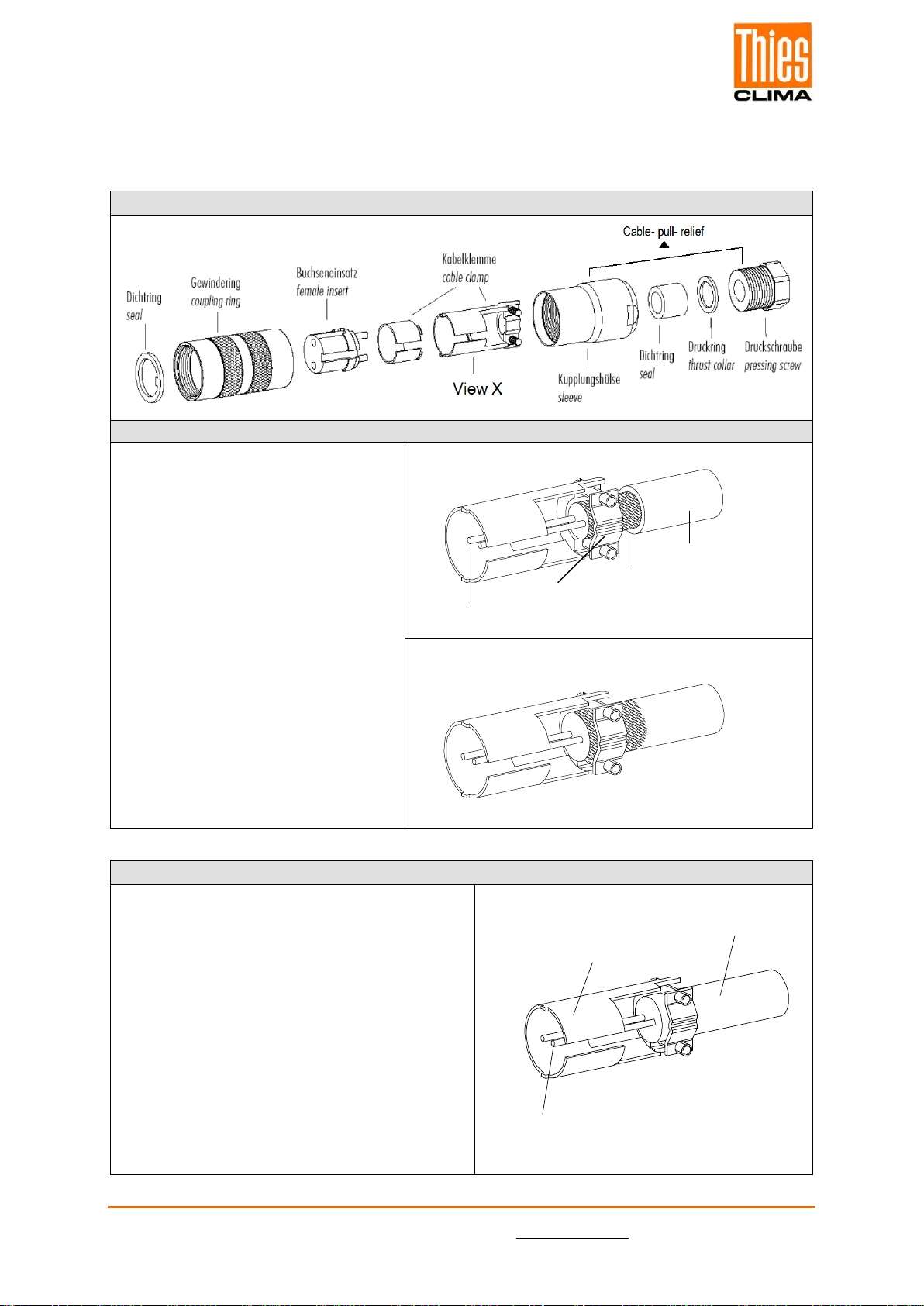
5.3.3 Plug and Cable Mounting
Coupling socket, Type: Binder, Serial 423, EMC with cable clamp
Cable connection: with cable shield
1. Stringing parts on cable acc. to
plan given above.
2. Stripping cable sheath 20mm
Cutting uncovered shield 15mm
Stripping wire 5mm.
Cable mounting 1:
Putting shrink hose or insolating
tape between wire and shield.
Cable mounting 2:
If cable diameter permits, put the
shield backward on the cable
sheath.
3. Soldering wire to the insert, posi-
tioning shield in cable clamp.
4. Screwing-on cable clamp.
5. Assembling remaining parts acc.
to upper plan.
6. Tightening pull-relief of cable by
screw-wrench (SW16 und 17).
Cable mounting 1
View X
wire
Cable clamp
shield
Cable shield
Cable mounting 2
View X
Cable connection:
without
cable shield
1. Stringing parts on cable acc. to plan given
above.
2. Stripping cable sheath 20mm.
3. Cutting uncovered shield 20mm.
4. Stripping wire 5mm.
5. Soldering wire to the insert.
6. Positioning shield in cable clamp.
7. Screwing-on cable clamp.
8. Assembling remaining parts acc. to upper
plan.
9. Tightening pull-relief of cable by screw-
wrench (SW16 und 17).
Cable clamp
Cable sheath
Wire
© Adolf Thies GmbH & Co. KG · Hauptstraße 76 · 37083 Göttingen · Germany 021887/12/20
Phone +49 551 79001-0 · Fax +49 551 79001-65 · inf[email protected] · www.thiesclima.com 13 - 34
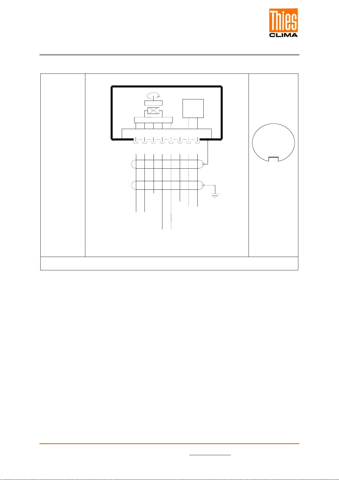
6 Connecting Diagram
Connection diagram acc. to chapter 5.3.2.1 no. 1, 3 and 4:
Order-No.
4.3151.0X.401
4.3151.1X.401*
3
4
Vers. / Power 3,3...42 VDC
8 pol. Binder Steckverb. / Plug
RS485 A
RS485 B
Digital Masse / Ground
2
1
N
S
Masse / Ground
5
6
7
Schirm
Shield
Erde / Earth
8
Versorgung / Power
Heizung / Heating
24 V AC / DC 25 W
Heizung
Heating
25 W
C P U
WG-Frequenz
View on the sol-
dered joint of
the counter plug
1
2
3
4
5
6
7
8
•*Order-no 4.3151.10.xxx (w/o heating) PIN 7 and 8 are not connected.

© Adolf Thies GmbH & Co. KG · Hauptstraße 76 · 37083 Göttingen · Germany 021887/12/20
Phone +49 551 79001-0 · Fax +49 551 79001-65 · inf[email protected] · www.thiesclima.com 14 - 34
Pin
Name
Function
1 WV-frequency Input wind velocity
2 GND Supply ground
3
+Vcc
Supply 3.3 ... 42V DC
4
Serial B
RS 485 (B)
5 Serial A RS 485 (A)
6 DGND Digital ground / ground wind velocity
7 HZG Heating supply:
Voltage: 24V AC/DC
Power: 25W
8
*Order-no 4.3151.10.xxx (w/o heating) PIN 7 and 8 are not connected.
6.1 Example Connection Diagram
© Adolf Thies GmbH & Co. KG · Hauptstraße 76 · 37083 Göttingen · Germany 021887/12/20
Phone +49 551 79001-0 · Fax +49 551 79001-65 · inf[email protected] · www.thiesclima.com 15 - 34
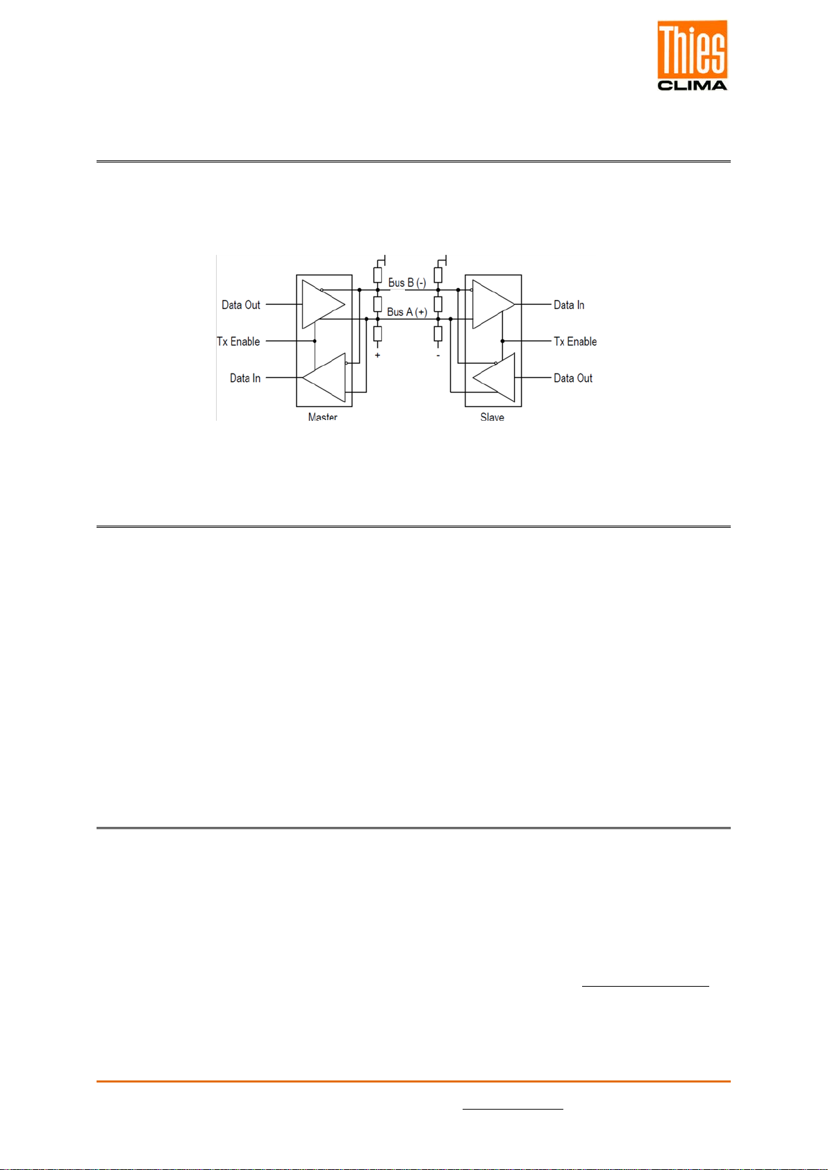
7 Serial Interface (RS485)
The wind direction transmitter has an RS485 interface, which is operated in half-duplex
mode. For a respective termination (terminating resistance) of the connecting cable must be
provided externally (no termination in the wind direction transmitter).
8 Placing into Operation
The wind direction transmitter is to be connected to a power supply and a RS485 interface,
as given in the connection diagram. With the connection of the supply voltage, and after a
delay of 5sec, the output of serial data starts automatically with the following setting/or the
MODBUS register are accessible:
Setting of interface:
Baud rate 9600 baud
Data bits 8 bit
Parity bit no
Stop bit 1
9 Serial Communication
The communication from the wind direction sensor has a command interpreter, which sup-
ports the following mode (see Command CI):
- MODBUS RTU
With the command interpreter can be read measurements and the behavior of the device can
be changed. This includes e.g. baud rate, framing, device ID and startup behavior.
In order to avoid an unwanted parameter adjustment some Commands (see Command list)
are secured by a password. This password must be sent before the actual command.
The wind direction sensor supports 1 password level.
•User-level (Password “1“).
Principle circuit diagram

© Adolf Thies GmbH & Co. KG · Hauptstraße 76 · 37083 Göttingen · Germany 021887/12/20
Phone +49 551 79001-0 · Fax +49 551 79001-65 · inf[email protected] · www.thiesclima.com 16 - 34
Attention:
The password-protected commands are released until one of the following
conditions is met:
- switch the supply voltage
- the command 00KY0 <CR> is sent
The register addresses of the command interpreter in MODBUS-RTU mode according to the
supported commands are listed in Table 1.
10 Commands and Description
For the wind direction transmitter the following commands are available:
Command Initial value
factory setting MODBUS
Register-
adress
Description Password
read1/ write2
Command BR
5
40005
Set the baudrate
Without
User
Command CI
0
40013
Selection of the command inter-
preter
Without
User
Command FB
1
40001
Quick start mode
Without
User
Command ID
1 (MODBUS)
40003
Set wind sensor ID
Without
User
Command KY
0
40009
Key / Password
Without
Without
Command MI
10
40027
Averaging interval
Without
User
Command OR
100
-
Output interval
Without
User
Command RS
0
40021
Check reset source or perform
reset
Without
User
Command SF
0
40019
Frame format
Without
User
Command SN
0
40007
Serial number
Without
-
Command SV
-
45005
Software-version.
Without
-
Command TR
-
-
Telegram request
Without
Without
Command TT
0
-
Automatic telegram output
Without
User
Table 1: Commands

© Adolf Thies GmbH & Co. KG · Hauptstraße 76 · 37083 Göttingen · Germany 021887/12/20
Phone +49 551 79001-0 · Fax +49 551 79001-65 · inf[email protected] · www.thiesclima.com 17 - 34
10.1Command BR
<id>BR<parameter><CR> Set the baudrate
Access: Read / write
Description: With command BR get/set the baudrate.
Parameter Description:
Parameter
Description
2
1200baud
3
2400baud
4
4800baud
5
9600baud
6
19200baud
7
38400baud
8
57600baud
Value range: 2 / 3 / 4 / 5 / 6 / 7 / 8
Initial value: 5
10.2 Command CI
<id>CI<parameter><CR> Selection of the command interpreter
Access: Read / write
Description: With Command CI get set the command interpreter.
Note:
If the identification number ID 0, switching to the MODBUS RTU interpreter is
not possible!
Parameter Description:
Parameter Description
1 MODBUS RTU
Value range: 0 bis 1
Initial value: 0

© Adolf Thies GmbH & Co. KG · Hauptstraße 76 · 37083 Göttingen · Germany 021887/12/20
Phone +49 551 79001-0 · Fax +49 551 79001-65 · inf[email protected] · www.thiesclima.com 18 - 34
10.3 Command FB
<id>FB<parameter><CR> Quick start mode
Access: Read / write
Description: With command “FB“ get set the quick start mode
Parameter Description: 0: quick start modus off
1: quick start modus on
Value range: 0...1
Initial value: 1
10.4 Command ID
<id>ID<parameter><CR> Identification Number
Access: Read / write
Description: This command sets the slave address (MODBUS RTU Inter-
preter). Only if the 'id' contained in the command matches the
one set in the sensor will send a telegram. After the 'id' has
been changed, the device immediately reacts only to com-
mands with the new ID.
'id'.Parameter Description: 0 Broadcast Slave-Addresse (MODBUS RTU Interpreter)
Value range: 1 … 247 (MODBUS RTU Interpreter)
Initial value: 1 (MODBUS RTU Interpreter)
10.5 Command KY
<id>KY<parameter><CR> Key / Password
Access: Read / write
Description: With command “KY“ get set the value of the key / password. To
chance parameters, the required password must be set.
Parameter Description: 0 no password
1 key / password at user level
Value range: 0 / 1
Initial value: 0

© Adolf Thies GmbH & Co. KG · Hauptstraße 76 · 37083 Göttingen · Germany 021887/12/20
Phone +49 551 79001-0 · Fax +49 551 79001-65 · inf[email protected] · www.thiesclima.com 19 - 34
10.6Command MI
<id>MI<parameter><CR> Averaging intervall
Access: Read / write
Description: With this command, the averaging interval for the sliding aver-
aging of the wind direction is set in seconds. The wind direction
is vectorially averaged with the unit vector (i.e., the magnitude
of the vector is 1).
Parameter Description: Averaging interval in seconds
Value range: 0...600
Initial value: 10
10.7 Command OR
<id>OR<parameter><CR> Output interval
Access: Read / write
Description: With command “OR” you set or query the output interval for the
automatic telegram output.
Parameter Description: Output interval in milliseconds
Value range: 100...60000
Initial value: 100
10.8Command RD
<id>RD<parameter><CR> Response delay
Access: Read / write
Description: With command “RD“ you set and query the response delay be-
tween receiving and command.
Parameter Description: Delay in milliseconds
Wertebereich: 0…50
Initialwert: 20

© Adolf Thies GmbH & Co. KG · Hauptstraße 76 · 37083 Göttingen · Germany 021887/12/20
Phone +49 551 79001-0 · Fax +49 551 79001-65 · inf[email protected] · www.thiesclima.com 20 - 34
10.9Command RS
<id>RS<parameter><CR> Reset
Access: Read / write
Description: Command “RS” queries the reset source (reading without pa-
rameter) or performs a reset (writing with any parameter).
The following reset sources can be output
Output
Meaning
POR
Power on reset
BODCORE
Brownout reset (µC core voltage)
BODVDD
Brownout reset (µC Vdd voltage)
EXT
External reset
WDT
Watchdog reset
SYST
System reset
Parameter Description: 1 Software Reset run
2 Watchdog Reset run
Value range: 1…2
Initial value: -
10.10 Command SF
<id>SF<parameter><CR> Frame format
Access: Read / write
Description: With command “SF“ set the frame format of the interface
Parameter Description: 0: 8N1 (8 data bits, no parity, 1 Stop bit)
1: 8N2 (8 data bits, no parity, 2 Stop bits)
2: 8E1 (8 data bits, straight parity, 1 Stop bit)
3: 8E2 (8 data bits, straight parity, 2 Stop bits)
4: 8O1 (8 data bits, uneven parity, 1 Stop bit)
5: 8O2 (8 data bits, uneven parity, 2 Stop bits)
Value range: 0…5
Initial value: 0
10.11 Command SN
<id>SN<CR> Serial number
Access: Reading
Description: With command “SN“ could read the serial number.
Parameter Description: -
Value range: -
Initial value: 0
This manual suits for next models
1
Table of contents
Other Thies CLIMA Transmitter manuals

Thies CLIMA
Thies CLIMA 5.4103.10.000 User manual

Thies CLIMA
Thies CLIMA 4.3120.22.012 User manual

Thies CLIMA
Thies CLIMA 4.3515.5 Series User manual

Thies CLIMA
Thies CLIMA 5.4041 1.00 Series User manual

Thies CLIMA
Thies CLIMA 4.3519 Series User manual

Thies CLIMA
Thies CLIMA 4.3515.30.000 User manual

Thies CLIMA
Thies CLIMA 4.3151.x0.400 Series User manual

Thies CLIMA
Thies CLIMA 4.3351.00.000 User manual


