7
R0 = valid R0-setting (f.ex. Pt100=100)
Ron = corrected R0-setting (equation below)
Ts = Uncorrected sensor temperature measured by
transmitter
Tn = corrected temperature to display; true
temperature
Kpt = Temp. coefficient of platin in RTD-table
corresponding temp. in question (abt. 0.385
ohm/°C)
Calculate new R0:
Ron = R0 * ( Ts * Kpt + 1 ) / (Tn * Kpt + 1)
F.ex. Sensor true temp. Tn = 100 °C and 6720 shows
Ts = 99.7 °C, R0 = 100 (basic value).
Calculate correction Ron = 100 * ( 99.7 * 0.385 + 1 /
(100 * 0.385 + 1) = 99.71
Potentiometers
Potentiometer resistance value is 50…500 ohm by 3-
wire connection and 0…1000 ohm by 2-wire
connection. When potentiometer glide moves from one
end to the other of the potentiometer range , display
value turns into Lo…Hi.
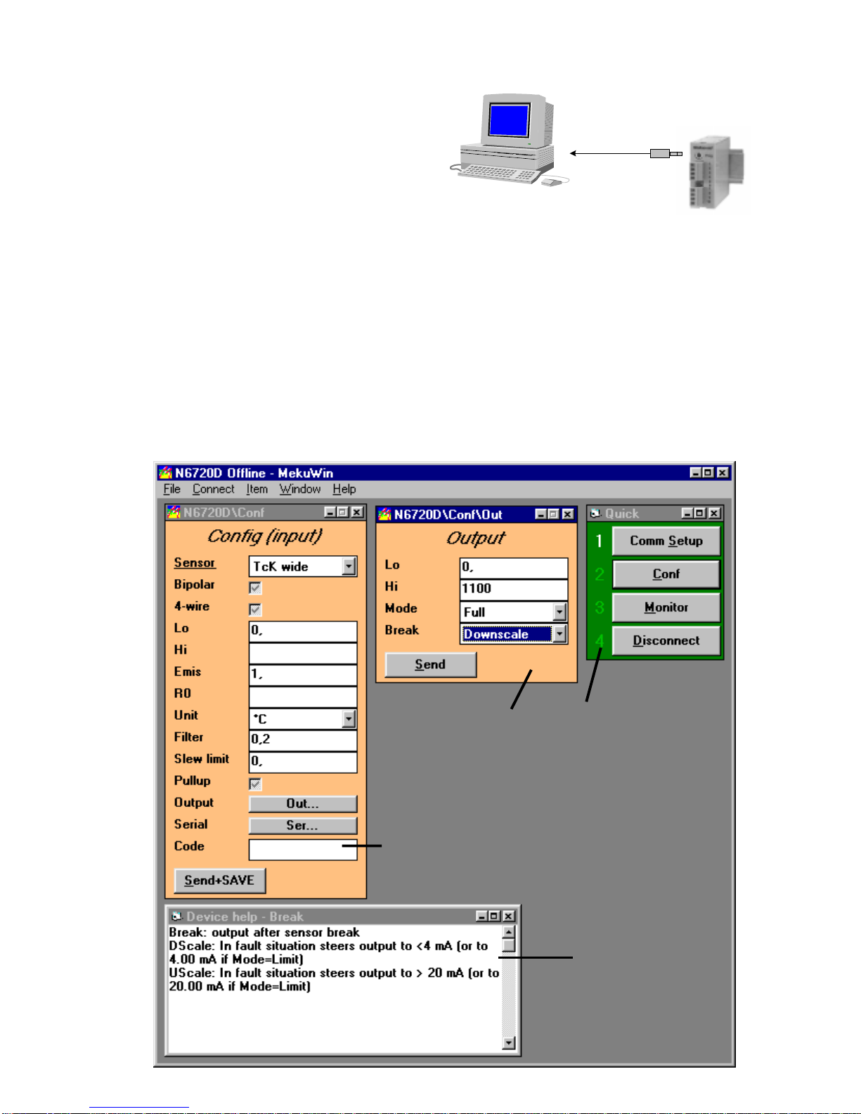
As you do not always use the whole potentiometer
range, this must be noticed in scaling. The easiest way
is to exploit output scaling as follows: set in input
window f.ex. Lo=0 and Hi=100. Drive potentiometer
from beginning to end and notice display values of 6720
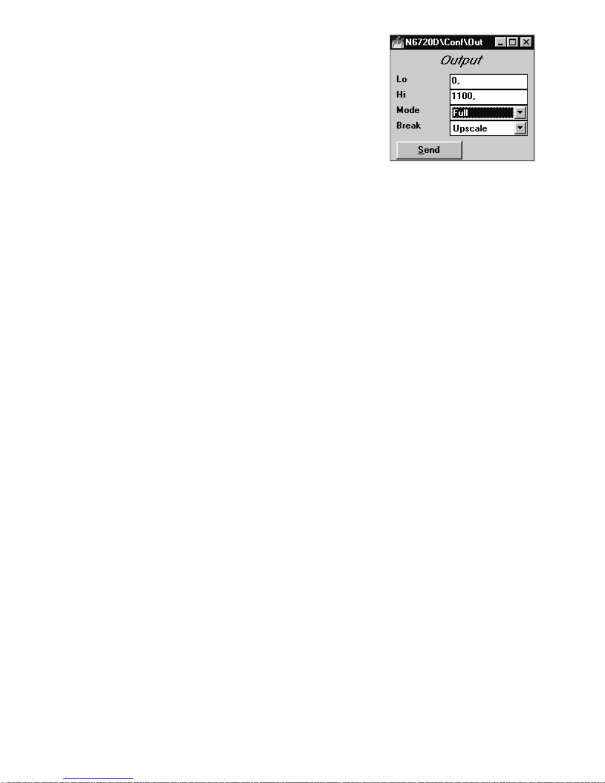
(monitor). Set these values in output window as Lo- and
Hi-values of mA-output.
When performing variable resistance measurement
(0…1000 ohm), the scaling is done like in point Abs.
sensor inputs.The sensor selection in menu = ohm.
0/4..20 mA and 0..5/10V process inputs
Input ranges: 0-5V, 0-10V, 0-20mA, 4-20mA. When
process signal is selected, scale the input first directly
as engineering units on monitor display. Set min. (Lo)
and max. (Hi) corresponding value, f.ex. input 0-10V
corresponds in display range 200-500. Set Lo=200 and
Hi=500 (output range is set in its own window). In case
of V-input, the jumper of the measuring card must be in
position 1-2 (mV-inputs do not need jumper setting).
Abs. inputs V, ±10 V, 20 mA and ohm
The abs. inputs as not scale in the same way as
process inputs simply by giving wanted display values to
monitor-display. In abs. inputs Hi-setting acts as
coefficient to which Lo-value is added. If input starts
from zero set Lo = 0 V (Ma, ohm), input is multiplied in
this case only by Hi-value.
You may select bipolar input by making cross to square
(Bip) in menu. If you do not need bipolar input, select
always unipolar input because then max. resolution of
A/D-conversion (1/64000) is available.
mV-inputs
mV inputs may be uni- or bipolar on range +-100 mV
(Bip). Unipolar range is more accurate because max.
resolution of A/D-conversion (1/64000) is available.
SelectionBip=Bipolar.
Infrared-sensors
Non contacting IR-sensor ranges are linearized on
whole measuring range for sensor types Exergen
140F-K (-40..+350°C) and 440F-K (-30..+600°C).
Emission coefficient corrects measured value to show
true temperature according to emissivity of target
object. Exergen sensors are calibrated for emission
coefficient 0.9 (grey body). If object emision coefficient
is 0.7 set Emis-value 0.7/0.9 = 0.77.
More details in point Thermocouple and IR-sensor
correcting coefficients (experimental Emis-control).
Other settings
Bip: Bipolarmeasurementis possible byunscaledinputs
(mV, V and mA). Measuring range covers also negative
value, f.ex. ±100mA.
4-wire: 4-wire measurement is possible by inputs ohm,
Pt or Ni. You must select 4-wire measurement also
measuring card (jumper).
Lo: Min. input value (process inputs, f.ex. 4 mA). By
unscaled inputs function Lo acts as zero shift and can
be used to correct sensor error. Value is given in
engineering unit f.ex. -5 °C. Zero shift is added first
eventually set Hi-coefficient.
Hi: Max. input value (process inputs, f.ex. 20 mA). By
unscaled inputs Hi acts as input multiplier by which you
can scale input value.Lo: You may correct sensor error
by zero shift.Value is given in sensor units, f,ex. -5 °C.
Zero shift is added first after eventually set Hi-value.
Emis: Emission or input multiplier, 1 = multiplier 1.
R0: RTD's 0 °C resistance value (f.ex. set Pt100 = 100
ohm)
Unit: C/F selection only with temperature sensors (Tc/
Pt/Ni).
Filt: filter
Notinuse=1.000.Normalfiltering0.200means(1/0.2=5)
thatthelatestmeasurementincludesonenewandfourold
measurements. Diminishing the filter value increases the
damping effect. Filtering behaves like RC-circuit.
Slew: slew rate
One measurement can not change measuring result
more than slew-value allows.
It can be used to eliminate interference peaks. One
measurement lasts abt.0.25 second so if slew value is
1, the measuring result can raise 4 units in one second
(f.ex. 4C/s). If you prefer not to to use this limiter, set
value larger than measuring range or value 0.