8
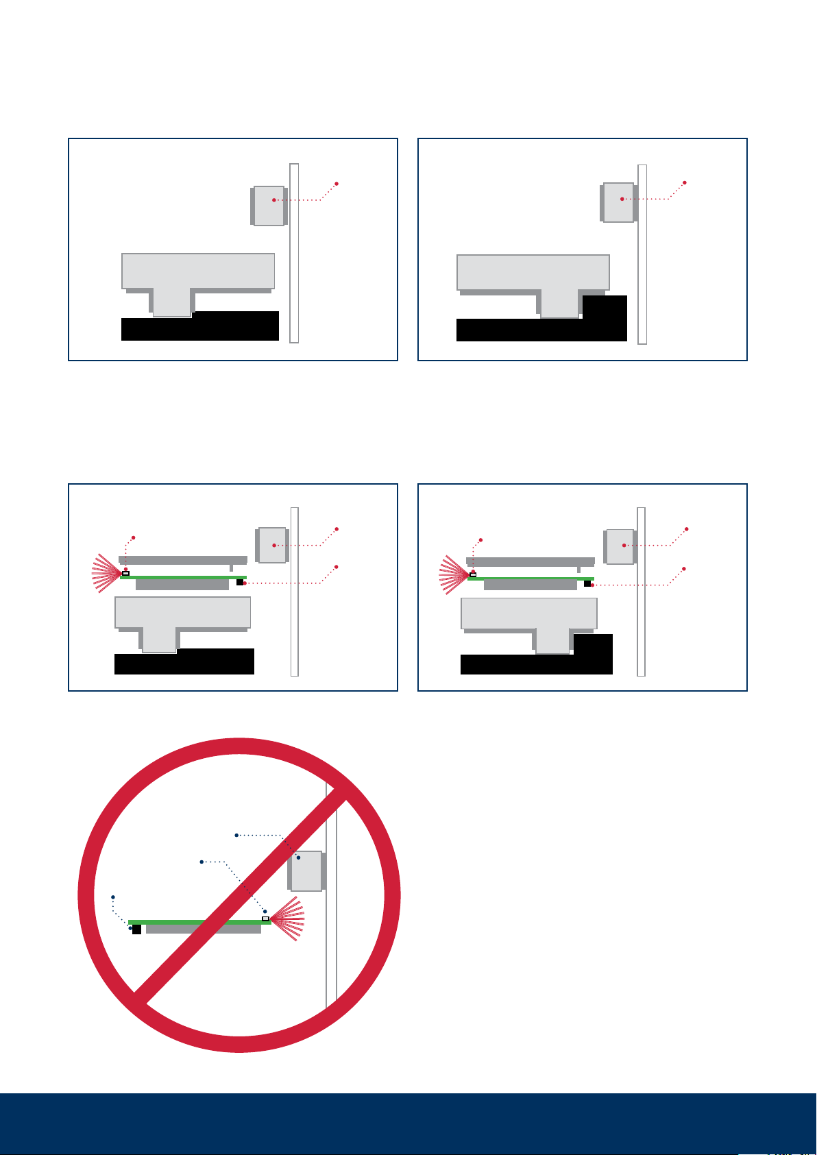
Variant upright
Windowpane
Windowpane
Variant
windowpane
Should upright mounting on the window frame
or mounting on the windowpane be neces-
sary, e.g., for space reasons, the transmitter
LED must also be aligned pointing away from
the magnet.
Alternative mounting variants
Door or hatch mounting
Ideally, the transmitter housing is aligned and
fixed on the frame and the magnet is attached
to the door leaf or the hatch. The specifica-
tions in the section ‘Positioning the magnet’
must be observed.
The circuit board must not be aligned
with the transmitter LED pointing to-
wards the magnet! If it is, then teach-
in, but no alarm, will be possible.
For bridging larger distances to
hatches or for optimal alignment of
the transmitter antenna, the use of
mounting adaptors (art. no. 100428,
100729) is recommended.
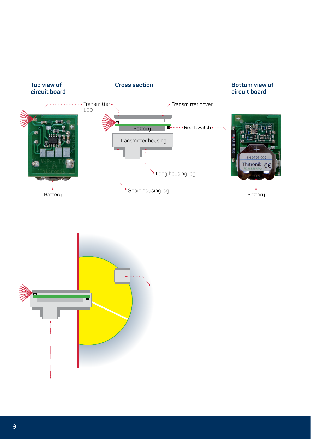
Fixing options
The wireless magnetic contacts are ideally
mounted with the help of the supplied adhe-
sive pads.
The mounting surface must be clean, dry and
grease-free. Please pretreat with a suitable
cleaning agent
as the wireless magnetic contacts may fall off
and thus unexpectedly trigger an alarm after
weeks or months of operation.
Do not process at temperatures below 15 °C.
The adhesive pads only reach their ultimate
strength after approx. 24 hours.
Should mounting with the adhesive pads not
be possible (e.g. to a door or hatch), screw
fixing is also possible. The corresponding
markings can be found on the inside of the
transmitter housing.
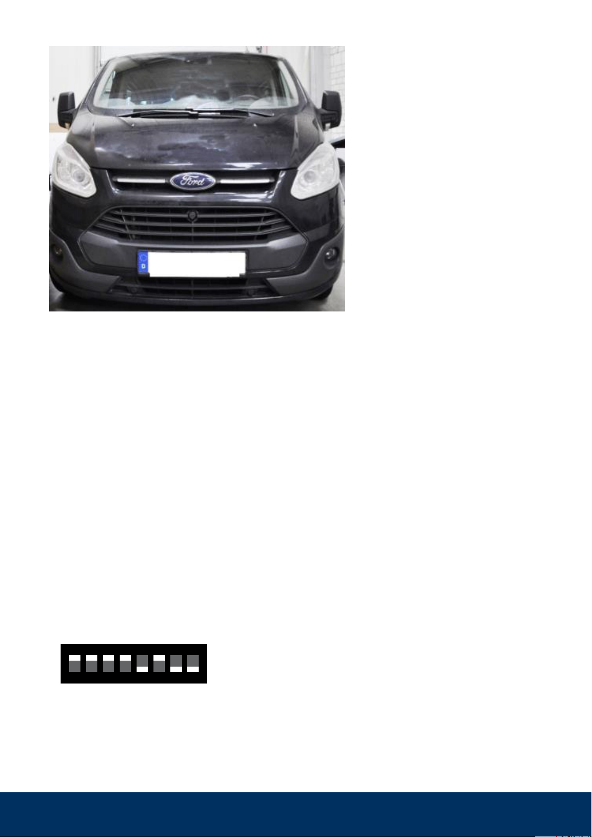
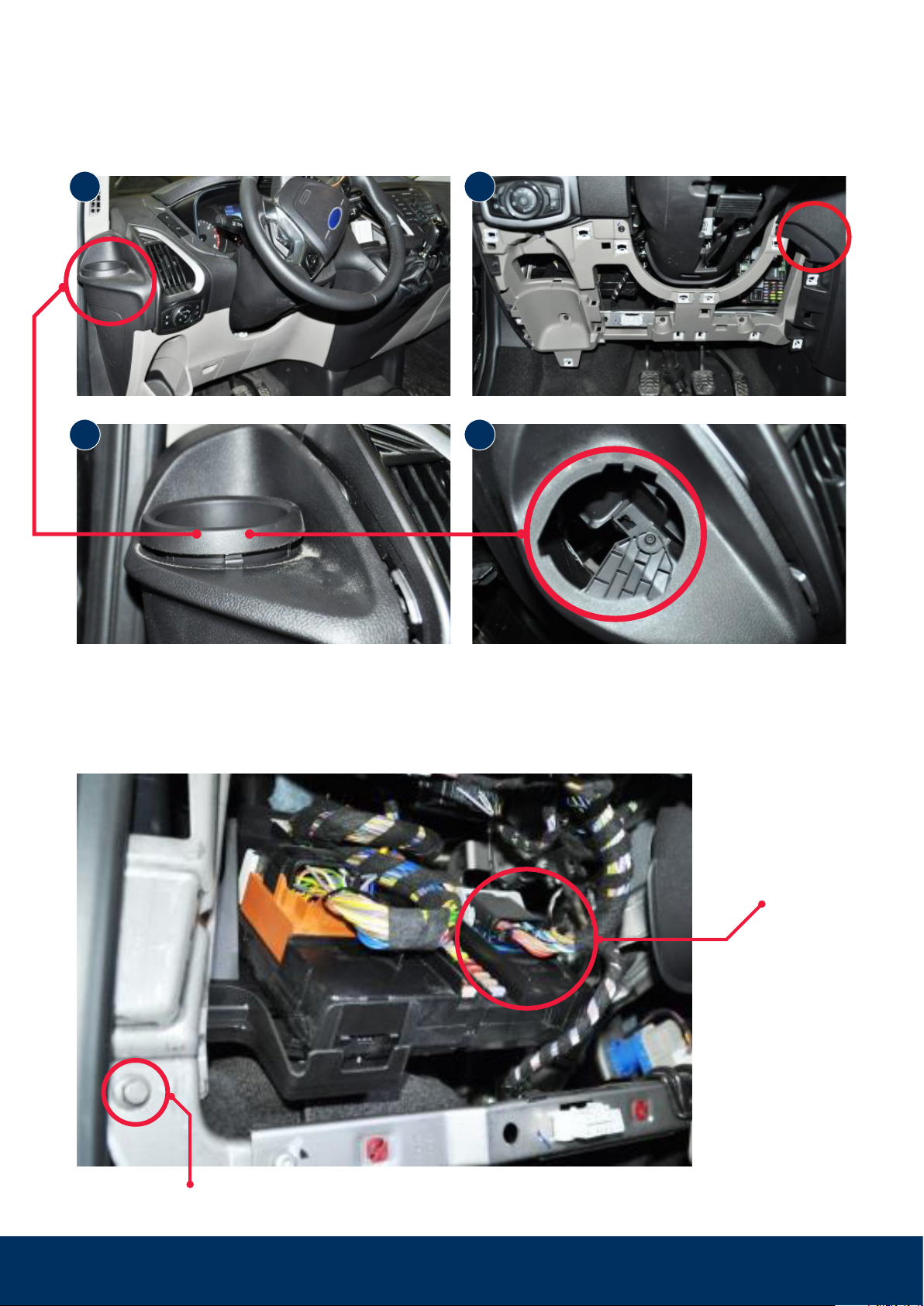
Mounting of wireless magnetic contacts 868 to windows, doors, hatches etc.