Thitronik WiPro III User manual

1
Updated 12/20
WiPro III Installation Manual
Ford Transit
2006+
Disclaimer:
This installation manual is intended for profes-
sional service companies. Appropriate back-
ground knowledge about work on vehicle elec-
trics and electronics is therefore required.
Improper interventions into the vehicle elec-
tronics and their components can under cer-
tain circumstances cause them to no longer
function as intended. This can considerably
endanger the installer (work, e.g., on the airbag
system) and the roadworthiness of the vehicle
and can result not only in property damage, but
also in personal injury.
Therefore, have all work on the vehicle elec-
tronics carried out by a qualified shop.
Thitronik GmbH is not liable for damage to
property and/or personal injury resulting from
improper, incorrect or only partially completed
installation work. The installing service compa-
ny is obligated to ensure that its connection
work neither is faulty in itself nor can lead to
faults or dangers on the vehicle.
The instructions in the WiPro installation man-
ual remain applicable. Unused inputs and out-
puts must be isolated.
Should the given vehicle conditions differ from
those described herein, please contact the
manufacturer or our technical support team.

WiPro III Installation Manual – Ford Transit from year of manufacture 2006.
2
We recommend a check of the vehicle conditions:
Is the horn working? Does the vehicle have electronic (e.g. warning lights, fault memory) or elec-
trical (e.g. lighting) faults? This should be recorded beforehand.
Aids/tools:
• Combination pliers, wire cutter
• 8 mm box spanner
• Cordless drill driver
• 8mm drill bit
Teach-in of wireless components (handheld transmitter, contacts etc.)
(before installation!)
1. Press the button to the right of the connector and hold it down until the system beeps. The
status LED is continuously lit.
2. Now activate each contact and gas alarm or radio cable loop to be stored several (2–3) times.
Successful storing is acknowledged through a beep and the LED goes out briefly.
Setting the CAN bus interface for vehicle type Transit
1. Remove the power supply.
2. On the 8-way DIP switch on the circuit board, set switches 1, 2 and 6 to the ‘on’ position.
1
↑
on
42 5 73 6 8
3. Close the housing again and continue with the installation.
The WiPro can be activated or deactivated via the original handheld radio transmitter for the ve-
hicle if the deadlock function is present (also double locking system; through this the cab doors
also cannot be opened from the inside). If this is not present, the WiPro is operated via the grey
handheld transmitter; the CAN connection continues to serve towards door evaluation.

WiPro III Installation Manual – Ford Transit from year of manufacture 2006.
3
Step 1: Remove dashboard panelling (glove compartment)
Release the glove compartment: press the clips in.
Release the fuse box.
Localise connectors C2, C5 and C6.
Remove the glove compartment.
Press the clips outwards and fold down.
C2 (brown)
C5 (light brown)
C6 (white)
5
1
3
2
4

WiPro III Installation Manual – Ford Transit from year of manufacture 2006.
4
Step 2: Fix mounting plate and make
connection to earth
An earthing point can be found to the right
of the central electronics box.
Loosen the screw with an 8mm spanner (screw is
very tight).
Slide in the mounting plate there and then screw
on the ring eyelets already present together with
the earthing eyelet through the metal holder and
tighten.
Be sure to screw the earthing screw in tightly.
Ring eyelets must not be loose!
Step 3: Make CAN connection and turn
signal actuation connection (connector
C6)
Use blue gel-filled branch connectors for all
connections.
Step 4: Make central locking system
evaluation connection (connector C2)
Use red branch connectors for both connections.
Pin Wire colour for
Ford
Cable colour on
WiPro
21 grey/orange → white/orange
31 violet/orange → violet/orange
19 brown/yellow → red/pink
Pin Wire colour on
Ford
Cable colour on
WiPro
24 grey/brown → blue
23 violet/orange → blue/black

WiPro III Installation Manual – Ford Transit from year of manufacture 2006.
5
Step 6: Install status LED
Drill an 8mm hole and insert the LED. Connect the
wire to the counterpart on the WiPro.
Step 7: Carry out a function test
Press the ‘lock’ button (deadlock) on the vehicle
key twice to arm the system. If a driver’s cab door
is open, the vehicle does not lock (and the horn
sounds, built-in vehicle function) and the system
is not activated.
The central control unit acknowledges the acti-
vation through a beep, flashing of the direction
indicators and flashing of the status LED.
Pressing the ‘unlock’ button on the vehicle key
disarms the system or interrupts the alarm.
The central control unit acknowledges the deac-
tivation through two beeps and flashing of the di-
rection indicators. The status LED stops flashing.
Trigger the alarm
With the system activated, open a driver’s cab
door or a door secured with a magnetic contact.
Alarm duration
The alarm sounds for approx. 30 seconds. The
visual alarm lasts approx. 180 seconds.
Alarm indication
The vehicle turn signal lights flash, the vehicle
horn sounds and the internal beeper emits a siren
tone. Pressing the ‘unlock’ button on the vehicle
key disarms the system or interrupts the alarm.
Signals during arming
If a series of short beeps is emitted during lock-
ing, one of the taught-in magnetic contacts is
open. However, the system is armed anyway.
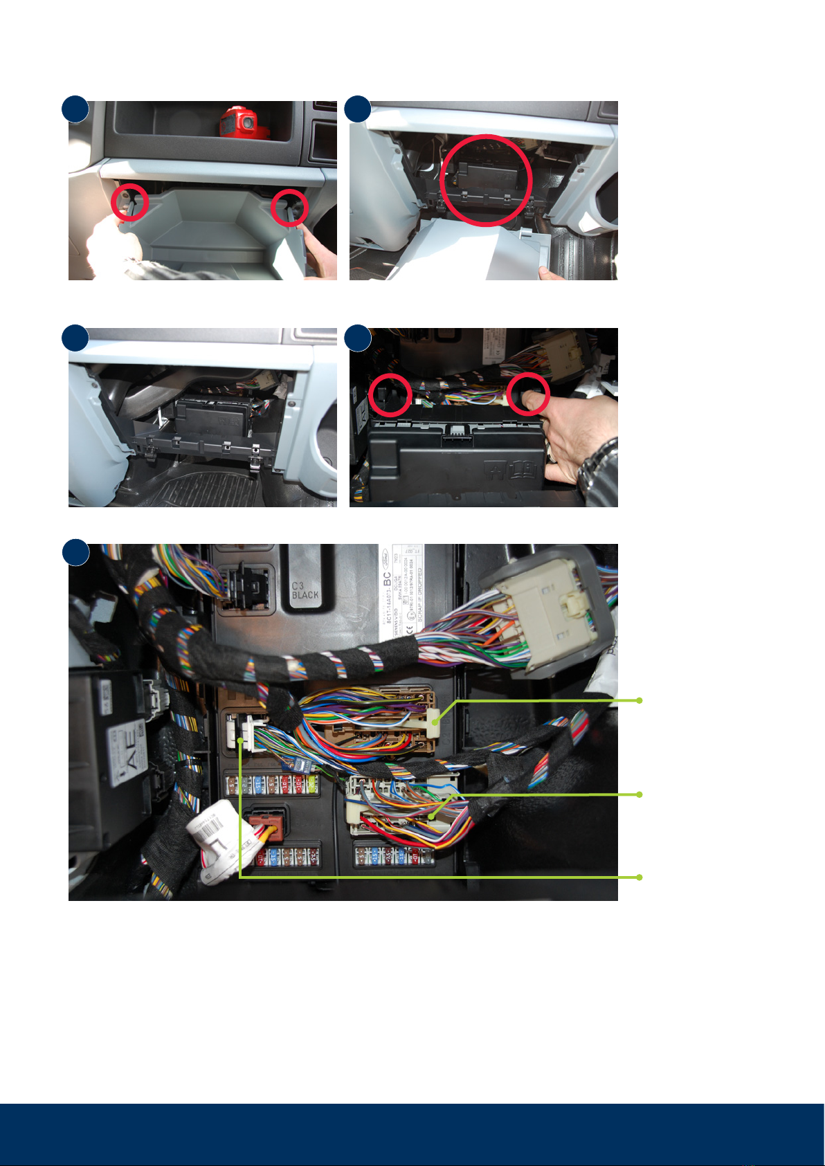
Step 5: Make connections for horn actuation,
ignition and power supply (connector C5)
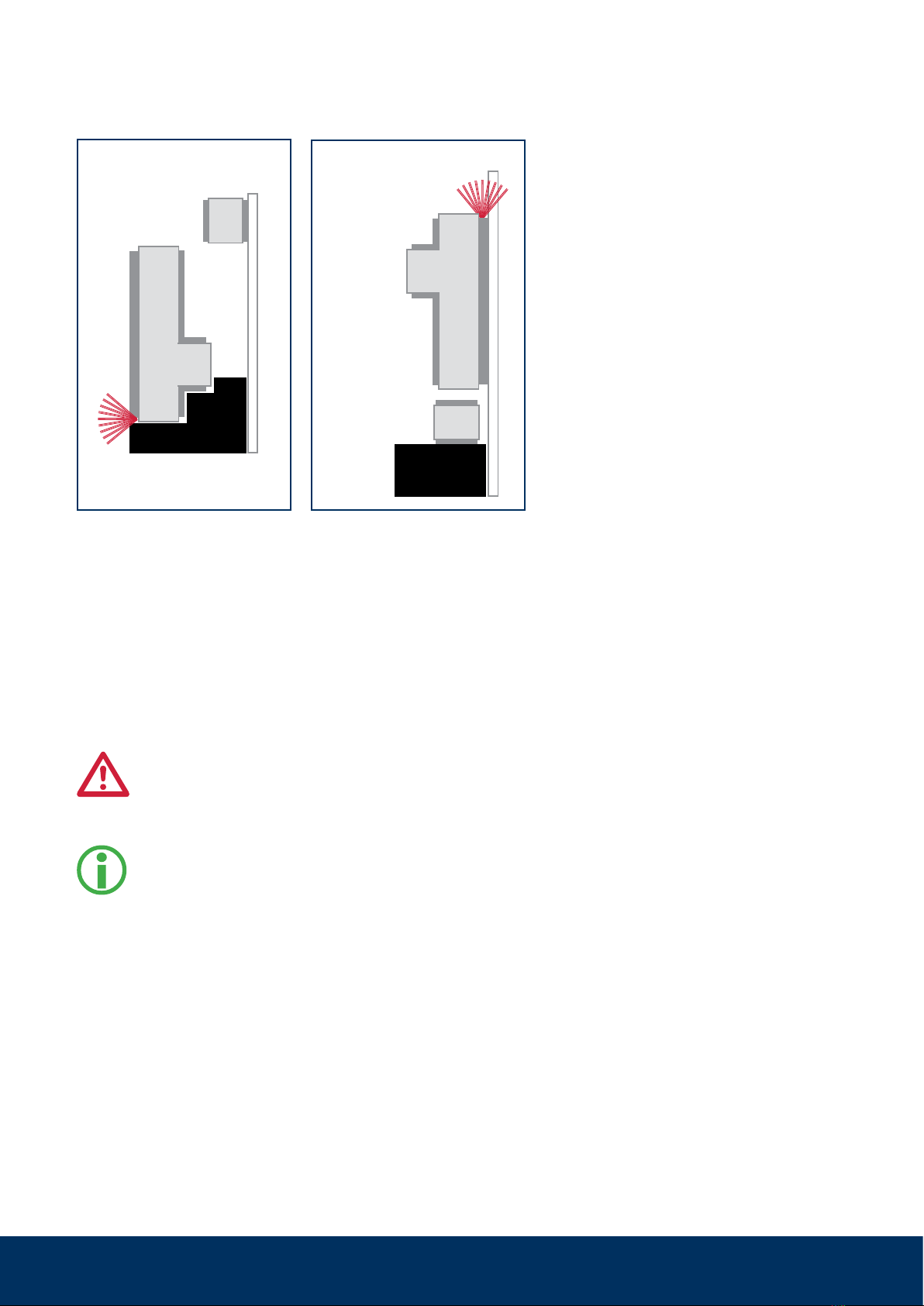
Connector C5 number is upside down:
The WiPro is protected via fuse F73 (15 A) – please enter into the operating manual
(customer’s copy). The WiPro buzzer sounds as soon as there is a power supply. The siren
may also sound and/or the flashing warning lights may be activated. Deactivate the latter
by pressing the hazard light switch.
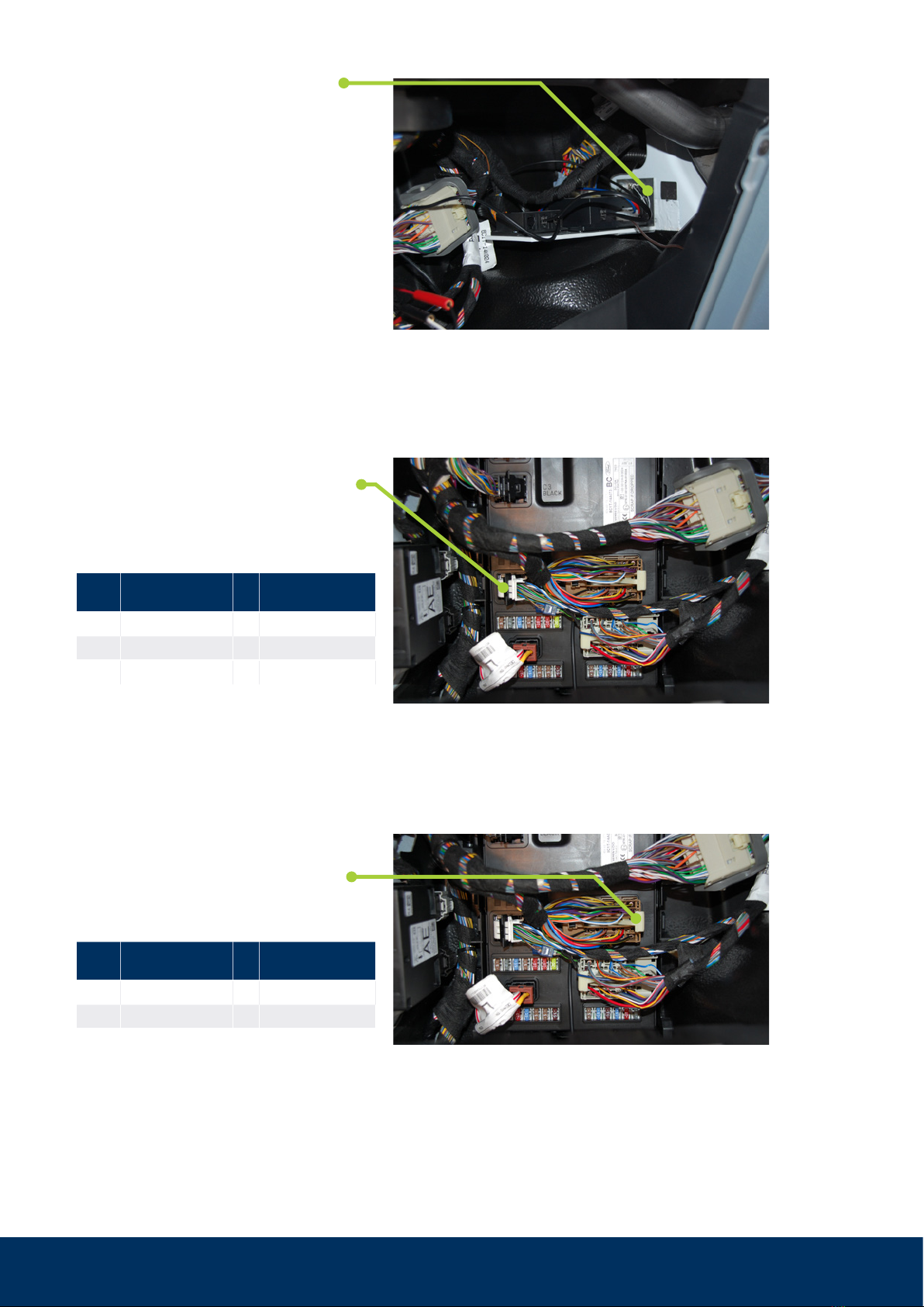
Pin Wire colour on
Ford
Cable colour on
WiPro
9 blue/white → pink
5 grey/orange → yellow
red →red
For pin 9 be sure to use the single blue/white wire.
Use red branch connectors for all connections.

6
Mounting of wireless magnetic contacts
868 to windows, doors, hatches etc.
Item no.: 100757, 100758

7
2. The circuit board is inserted into the transmitter housing (transmitter LED oriented upwards pointing away from
magnet) and the transmitter cover is snapped on.
The circuit board must not be
aligned with the transmitter LED
pointing towards the magnet!
If it is, then teach-in, but no alarm, will be possible.
Reed switch
Transmitter
LED
Magnet
1. The orientation of the transmitter housing on the window frame depends on the available space (frame profile,
distance to the roller blind or window).
Variant lying
left
Window frame
Windowpane
Transmitter housing
Magnet Magnet
Window frame
Windowpane
Transmitter housing
Variant lying
right
Magnet
Window frame
Transmitter LED
Windowpane
Transmitter housing
Reed
switch
Battery Battery
Variant lying left
Magnet
Window frame
Windowpane
Transmitter LED
Transmitter housing
Reed
switch
Variant lying right
Mounting of wireless magnetic contacts 868 to windows, doors, hatches etc.

8
Variant upright
Windowpane
Windowpane
Variant windowpane Should upright mounting on the window
frame or mounting on the windowpane
be necessary, e.g., for space reasons,
the transmitter LED must also be aligned
pointing away from the magnet.
Alternative mounting variants
Door or hatch mounting
Ideally, the transmitter housing is aligned and
fixed on the frame and the magnet is attached
to the door leaf or the hatch. The specifica-
tions in the section ‘Positioning the magnet’
must be observed.
The circuit board must not be aligned with the
transmitter LED pointing towards the
magnet! If it is, then teach-in, but no
alarm, will be possible.
For bridging larger distances to
hatches or for optimal alignment of the trans-
mitter antenna, the use of mounting
adaptors (art. no. 100428, 100729) is
recommended.
Fixing options
The wireless magnetic contacts are ideally
mounted with the help of the supplied adhe-
sive pads.
The mounting surface must be clean, dry and
grease-free. Please pretreat with a suitable
cleaning agent
as the wireless magnetic contacts may fall off
and thus unexpectedly trigger an alarm after
weeks or months of operation.
Do not process at temperatures below 15 °C.
The adhesive pads only reach their ultimate
strength after approx. 24 hours.
Should mounting with the adhesive pads not
be possible (e.g. to a door or hatch), screw
fixing is also possible. The corresponding
markings can be found on the inside of the
transmitter housing.
Mounting of wireless magnetic contacts 868 to windows, doors, hatches etc.

9
Transmitter
LED
Reed
switch
Transmitter housing
Transmitter cover
Battery
Battery Battery
Long housing leg
Short housing leg
Top view of
circuit board
Bottom view of
circuit board
Cross section
Battery
Magnet
22-30mm
Positioning the magnet
As long as the magnet is in the yellow area, its
magnetic field keeps the reed switch closed. If the
magnet moves from there into the blue area, the
reed switch is opened and a transmission opera-
tion is triggered (transmitter LED flashes). With an
armed alarm system, this leads to an alarm.
The magnet should not be mounted past the red
line and should later only move between the yellow
and blue areas.
The orientation of the transmitter housing (long leg /
short leg) is not important in this representation.
Alignment of circuit board in transmitter housing
(as-delivered condition) and positions of components.
Mounting of wireless magnetic contacts 868 to windows, doors, hatches etc.
Other manuals for WiPro III
3
This manual suits for next models
2
Other Thitronik Automobile Accessories manuals