Kleinn GMHD20-734 User manual


Install Guide GMHD20-734
Page | 2 Revision: BETA
Table of Contents
1. Application Chart .................................................................................................................................. 4
1.1. List of compatible vehicles............................................................................................................ 4
1.2. Incompatible Vehicle Features & Trim Packages.......................................................................... 4
1.3. Aftermarket Product Compatibility .............................................................................................. 4
2. Before You Start.................................................................................................................................... 5
3. Installation Overview ............................................................................................................................ 5
3.1. Kit Layout & Location.................................................................................................................... 5
4. List of Tools & Supplies ......................................................................................................................... 6
4.1. Standard Tools .............................................................................................................................. 6
4.2. Specialty Tools .............................................................................................................................. 6
4.3. Consumables................................................................................................................................. 6
5. Parts List................................................................................................................................................ 7
5.1. Primary Kit Components ............................................................................................................... 7
5.2. Fittings & Related Items................................................................................................................ 8
5.3. Electrical Components & Related Items ....................................................................................... 9
5.4. Mounting Brackets........................................................................................................................ 9
5.5. Hardware & Related Items.......................................................................................................... 11
6. Recommended Routing of Air Tubing & Wire ....................................................................................13
7. Bench Assembly ..................................................................................................................................14
7.1. Rubber Trim – Cutting & Installation .......................................................................................... 14
7.2. Air Horns – Disassembly & Preparation...................................................................................... 15
7.3. Air Horns – Bracket Install & Preparation...................................................................................17
7.4. Air Tank – Fitting Installation ......................................................................................................18
7.5. Compressor – Fitting Installation................................................................................................ 19
7.6. INF-1 – Fitting Installation........................................................................................................... 19
8. On-Vehicle Assembly ..........................................................................................................................20
8.1. Air Horn – Driver Side Installation .............................................................................................. 20
8.2. Air Horn – Passenger Side Installation........................................................................................ 24
8.3. Air Horn – Center Horn Installation ............................................................................................26
8.4. Compressor Installation..............................................................................................................27
8.5. Tank Installation.......................................................................................................................... 32
8.6. Air Tank Installation ....................................................................................................................35

Install Guide GMHD20-734
Page | 3 Revision: BETA
8.7. 1302 Remote Air Quick Connect.................................................................................................36
8.8. Final System Plumbing ................................................................................................................36
9. On-Vehicle Electrical Installation ........................................................................................................37
9.1. Solenoid Connector – Reconfigure the Housing & Wiring..........................................................37
9.2. Attach Relay & Fuse to Vehicle ................................................................................................... 38
9.3. Install Horn Button...................................................................................................................... 38
9.4. Route Wiring & Make Connections.............................................................................................39
10. Testing the Air System ....................................................................................................................40
10.1. Air Compressor Test................................................................................................................40
10.2. Air Horn Test ...........................................................................................................................40
10.3. Quick Connect Coupler Test.................................................................................................... 40
11. Maintenance ...................................................................................................................................41
12. Warranty Information.....................................................................................................................42

Install Guide GMHD20-734
Page | 4 Revision: BETA
1. Application Chart
This kit is a direct bolt-on aftermarket product. The vehicles listed in the below table are considered to
be compatible with this aftermarket kit. Every effort has been made to verify fitment on these vehicles
in their factory condition.
WARNING: Before unpacking your kit, review this manual in full & verify the correct space & mounting
locations exist with your trim package.
1.1. List of compatible vehicles
Year
Make
Model
Drivetrain
Engine
Cab
Bed
Trim
2020 + Chevy
Silverado
2500HD
2WD
4WD
Vortec 6.6L
Duramax 6.6L Crew
Standard
Long
Work Truck
Custom
LT
LTZ
High Country
Silverado
3500HD
2020 + GMC
Sierra
2500HD Standard
Long
Pro
SLE
SLT
AT4
Denali
Sierra
3500HD
NOTE: Drilling holes may be required for installing ground wires and switches based on the installer’s
preference.
1.2. Incompatible Vehicle Features & Trim Packages
This kit may not be compatible with the following vehicle features / trim packages:
•All OEM chassis cab frames with service boxes or flat beds, as purchased from dealerships.
1.3. Aftermarket Product Compatibility
This kit has been designed to be compatible with the following products from leading manufacturers:
•Amp Research Power Steps
This kit has not been designed to be compatible with the following products:
•N/A

Install Guide GMHD20-734
Page | 5 Revision: BETA
2. Before You Start
Read this manual in its entirety before starting installation. Verify you have all the parts listed & that you
clearly understand the installation procedure. Contact KLEINN Technical Support with any questions you
may have.
Installation of this kit requires moderate mechanical aptitude.
Use the proper tools, supplementary lighting, and safety equipment when installing this kit.
3. Installation Overview
3.1. Kit Layout & Location
Item
No. Description Mounting Location
Approx.
Install
Time
1 6450RC Air Compressor
Along the passenger side frame rail, between
driver & passenger door
1 Hour
2 6353RT Air Tank
Suspended under vehicle, between driver & rear
passenger seat
1 Hour
3 730 Air Horns
Inside cavity of bedside steps | Suspended under
vehicle, between fuel tank & exhaust system
2 Hours
4
1302 Relocation Kit
TBD by Installer/Customer
(Not Illustrated)
N/A
Note: Wiring time is not factored into the overall install time of this kit. See Section 6 for suggested
wiring & plumbing routes.
Figure 1- Kit Layout

Install Guide GMHD20-734
Page | 6 Revision: BETA
4. List of Tools & Supplies
4.1. Standard Tools
•Mechanic’s 1/4" & 3/8” Drive & Socket Set – Imperial & Metric
•Combination wrenches – Imperial & Metric
•Hex wrenches – Imperial & Metric
•Screwdriver Set – #1, #2
•Wire Cutters
•Wire Strippers
•Wire Crimpers
•Utility Knife or Equivalent
•Precision Screwdriver or Small Pry Tool
4.2. Specialty Tools
•1/4” & 3/8” Universal Joints
•1/4" & 3/8” Extensions
•Multimeter, Test Light, or Equivalent
•Heat Gun
•Trim Panel Removal Tools
•Drill Driver & Bits
•Impact Driver & Bits
•Wire Running Kit or Equivalent
4.3. Consumables
•Quality Electrical Tape
•Medium Strength Thread Locker
•Sandpaper, Wire Brushes or Equivalent
•Extra Zip Ties
•Touch-up Paint

Install Guide GMHD20-734
Page | 7 Revision: BETA
5. Parts List
Unpackage & organize the kit contents and verify all parts listed below are included. Contact KLEINN
Support if any questions arise.
5.1. Primary Kit Components
NOTE: Items in this section may come in their own packages which may include additional items,
hardware, or documentation.
Item
No.
Qty Part No. Description Picture
1.
1 6450RC 150 PSI Waterproof Air Compressor
Kit
2.
1 6353RT 2.6 Gal. Air Tank, 9-Port
3.
1 730 730 Series Air Horn Kit
4.
1 1302 Quick Disconnect Air Relocation Kit
NOTE: May be located within INF-1 Kit
5.
1 INF-1 Tire Inflator Kit

Install Guide GMHD20-734
Page | 8 Revision: BETA
5.2. Fittings & Related Items
Item
No.
Qty Part No. Description Picture
F1
1 51414F ¼” NPT Female to ¼” Compression
F2
1 51414L ¼” NPT Male to ¼” Compression,
Elbow
F3
1 51414NPTL ¼” NPT Male to ¼” NPT Female,
Elbow
F4
1 52175 175 PSI Pop-Off Safety Valve
F5
3 50040 ¼” NPT Male, Hex Plug
F6
1 52835 ¼” NPT Male Drain Plug
F7
1 51214L ¼” NPT Male to ½” Compression,
Elbow
F8
1 2151 Pressure switch,
110 PSI On – 145 PSI Off
F9
12 ft
&
12 ft
25014 1/4" Air Tubing
NOTE: May be located within INF-1 Kit
F10
10 ft PFT38A 3/8” Air Tubing
F11
2 JUICE NPT Thread Sealant
Install Guide GMHD20-734
Page | 9 Revision: BETA
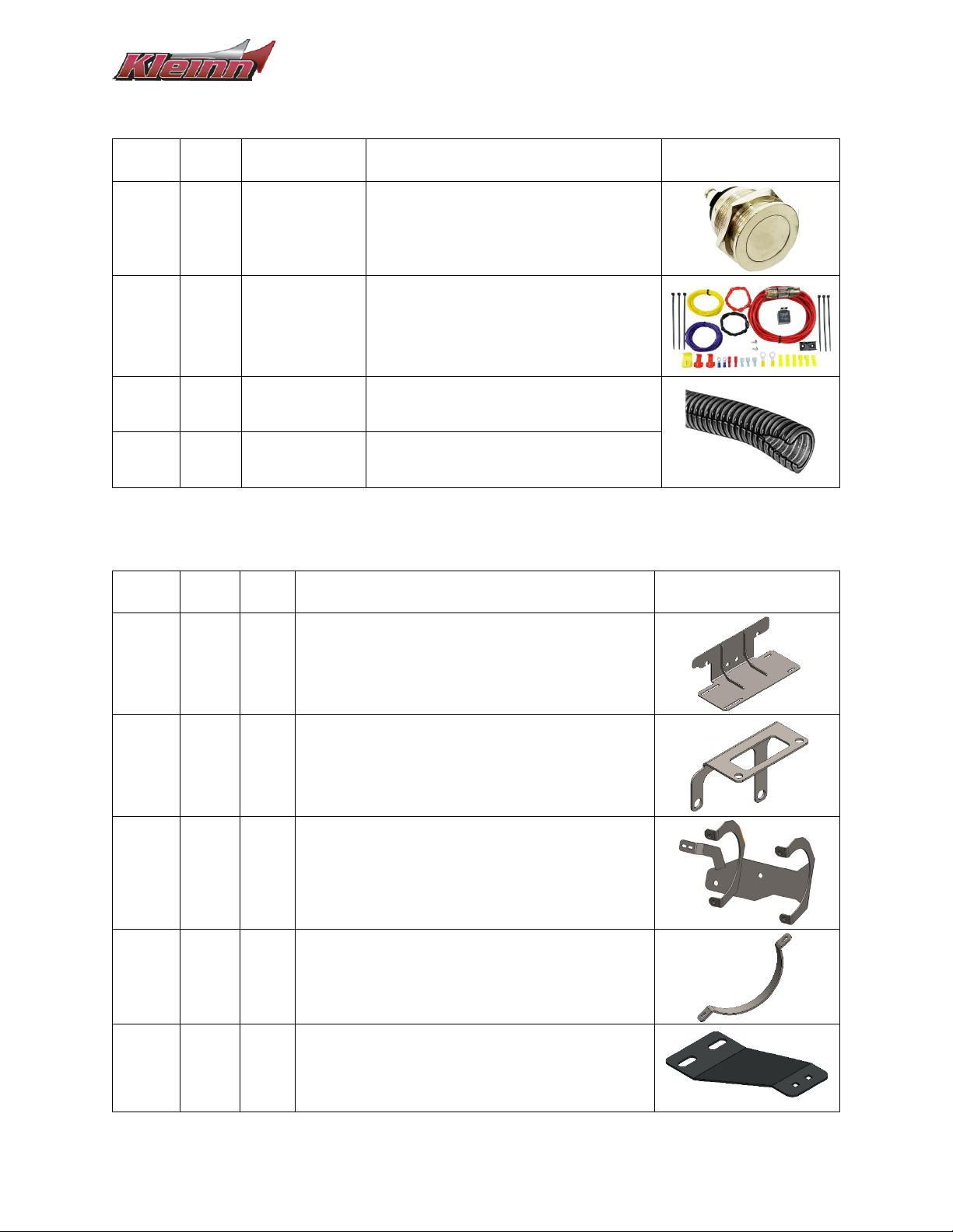
5.3. Electrical Components & Related Items
Item
No.
Qty Part No. Description Picture
-
1 320 Momentary Switch, NO
-
1 N/A Wire Kit
-
30 ft N/A 3/8” Loom Pack
-
10 ft N/A 1/4" Loom Pack
5.4. Mounting Brackets
Item
No.
Qty
Part
No.
Description Picture
-
1 - Compressor Bracket
-
1 - Module Relocation Bracket
-
1 - Tank Bracket
-
2 - Tank Strap
-
1 - Passenger Side Horn Bracket, Front

Install Guide GMHD20-734
Page | 10 Revision: BETA
-
1 - Passenger Side Horn Bracket, Rear
-
1 - Driver Side Horn Bracket, Front
-
1 - Driver Side Horn Bracket, Rear
-
1 - Center Horn Bracket

Install Guide GMHD20-734
Page | 11 Revision: BETA
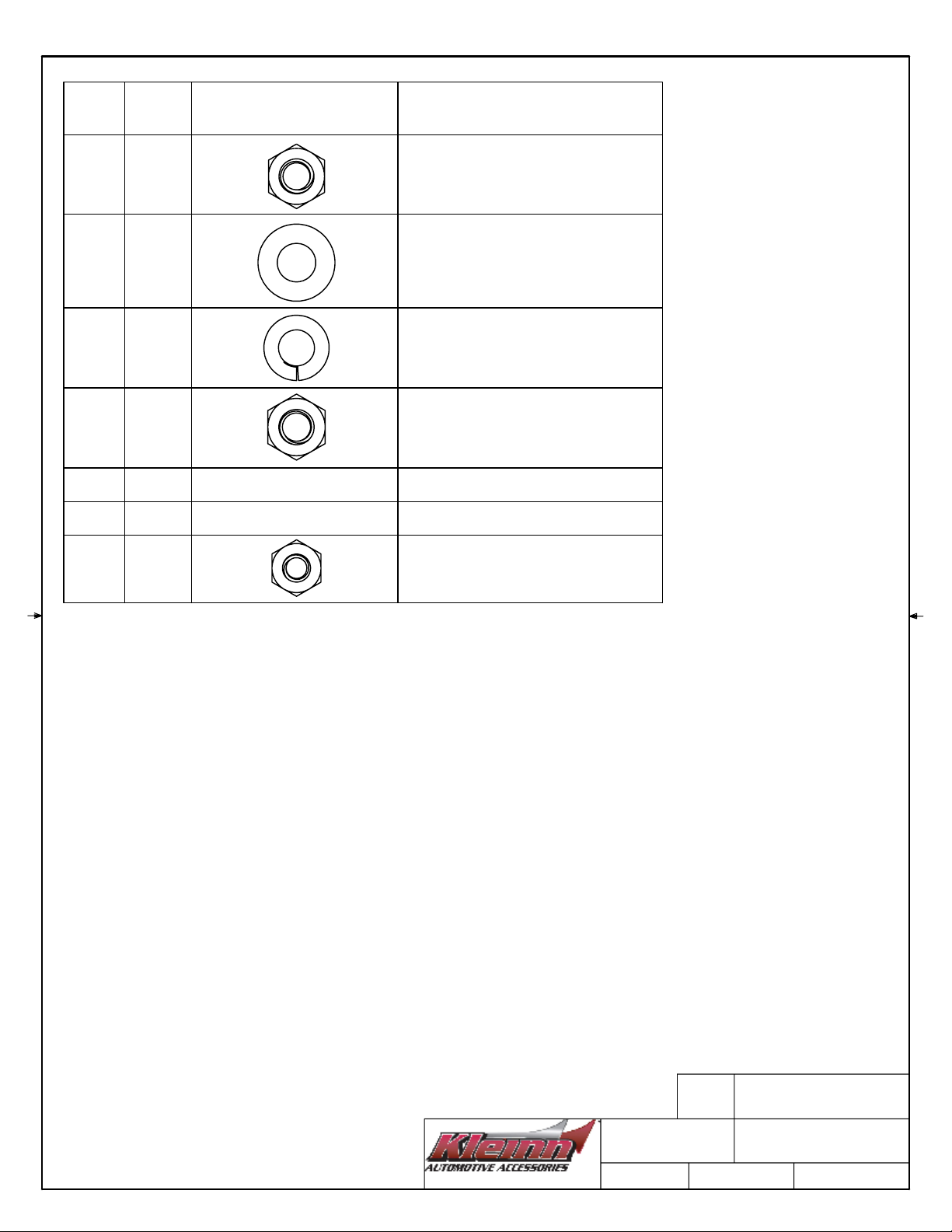
5.5. Hardware & Related Items
Print out the hardware sheets at the end of this section at 100% Scale to facilitate hardware
identification.
Item
No.
Qty Hardware Size Description Picture
H1
4 M10 x 1.5, 100mm
Length Hex Head Bolt
H2
4 M10 x 1.5 Hex Nut
H3
8
M10
Flat Washer
H4
4 Split-Lock Washer
H5
6 1/4"-20, 1” Length Socket Head Cap Screw
H6
8
1/4"
SAE Washer
H7
6 Split-Lock Washer
H8
4 5/16”-18, .75” Length Square Neck Carriage Bolt
H9
4 5/16”-18 Hex Nut
H10
4
5/16”
SAE Washer
H11
4 Split-Lock Washer
H12
6 M8 x 1.25 Hex Nut
H13
3 M6 x 1 Nylon Lock Nuts*

Install Guide GMHD20-734
Page | 12 Revision: BETA
H14
2 ft - Narrow U-Strip, Rubber *
H15
2 1/4"-20 Hex Nut
*Not Illustrated on the Scale Sheets

NOTE:
SCALE IMAGES OF PRE-PACKAGED HARDWARE INCLUDED WITH
THE COMPRESSOR ARE NOT ILLUSTRATED.
SCALE IMAGES OF UNIQUE & EASILY IDENTIFIABLE HARDWARE ARE
NOT ILLUSTRATED.
THIS DOCUMENT IS DESIGNED TO BE VIEWED / PRINTED AT 100% OR
"ACTUAL SIZE".
ITEM
#
QTY
SCALE IMAGE
H1
4
H2
4
H3
8
H4
4
H5
6
H6
8
H7
6
H8
4
4/14/2023
SCALE HARDWARE
GMHD20-734
0
NOTE:
SCALE IMAGES OF PRE-PACKAGED HARDWARE INCLUDED WITH
THE COMPRESSOR ARE NOT ILLUSTRATED.
SCALE IMAGES OF UNIQUE & EASILY IDENTIFIABLE HARDWARE ARE
NOT ILLUSTRATED.
THIS DOCUMENT IS DESIGNED TO BE VIEWED / PRINTED AT 100% OR
"ACTUAL SIZE".
ITEM
#
QTY
SCALE IMAGE
NOTES
H9
4
EASILY CONFUSED WITH H12,
CHECK THREADS BEFORE
INSTALL
H10
4
-
H11
4
-
H12
6
EASILY CONFUSED WITH H9,
CHECK THREADS BEFORE
INSTALL
H13
3
ITEM NOT ILLUSTRATED
-
H14
2 FT
ITEM NOT ILLUSTRATED
-
H15
2
-
4/14/2023
SCALE HARDWARE
GMHD20-734
0

Install Guide GMHD20-734
Page | 13 Revision: BETA
6. Recommended Routing of Air Tubing & Wire
The below figures are a recommendation of the routing paths for both the air tubing & the wiring. Verify
routing paths, wire lengths, & fuse/relay component locations before cutting the included wire.
Reference Section 9 (On-Vehicle Electrical Installation) for a detailed electrical connection guide.
Figure 2- Recommended Air Tubing Routing
Figure 3- Recommended Electrical Routing (Grounding Points Not Shown)

Install Guide GMHD20-734
Page | 14 Revision: BETA
7. Bench Assembly
7.1. Rubber Trim – Cutting & Installation
1. Cut hardware H14 & run the channel along the curved portions of the tank bracket as shown
below.
Figure 4- Rubber Trim Installation

Install Guide GMHD20-734
Page | 15 Revision: BETA
7.2. Air Horns – Disassembly & Preparation
1. Remove all three (3) air horns form the mounting base.
2. Discard the (white) plastic shipping covers on each air horn driver & discard the mounting plate.
3. Retain the hardware used to secure the air horns to the mounting plate.
4. Detach the air tubing that connects the center horn from the left & right horns.
Figure 5- Air Horn Disassembly & Separation
5. Unscrew each trumpet from its respective air horn driver and set aside.
6. Completely remove the air tubing from the center horn solenoid assembly
Figure 6- Trumpet Removal & Solenoid Installation
7. Using KLEINN JUICE, apply a few drops onto the male threads of the (middle) horn driver and
install the solenoid valve (included in the horn box) with the arrow pointing towards the horn
driver. Reference the following figure.
8. Using KLEINN JUICE, install the included compression fitting onto the other end of the solenoid
as shown in the following figure.
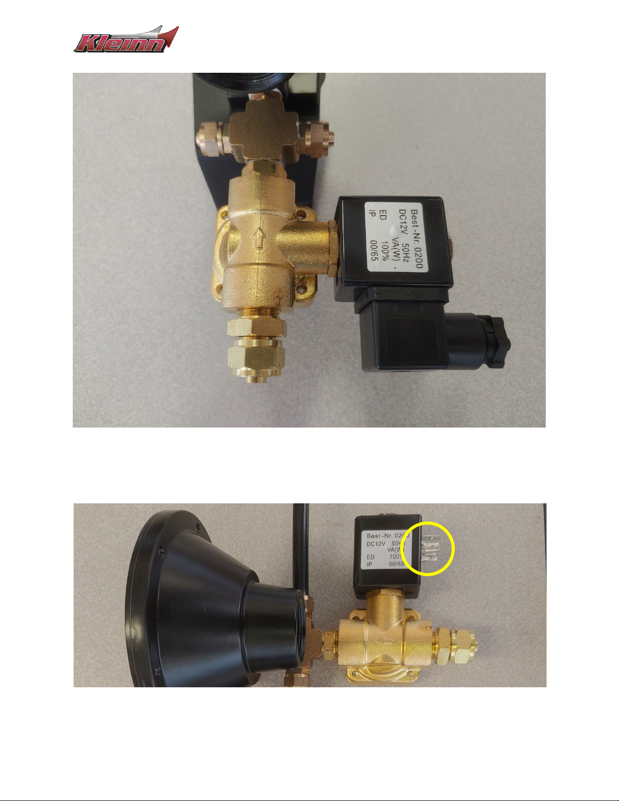
Install Guide GMHD20-734
Page | 16 Revision: BETA
Figure 7- Solenoid Installation (Close Up)
9. Detach & retain the electrical connector for the solenoid as shown below.
Figure 8- Solenoid Electrical Connector Removal

Install Guide GMHD20-734
Page | 17 Revision: BETA
7.3. Air Horns – Bracket Install & Preparation
1. Using the retained air horn mounting hardware & Qty 6 of additional hardware, H12, install the
air horn drivers to their respective mounting bracket as shown in the below figures.
2. Tighten the fasteners snug so the drivers do not move freely but can be adjusted with force.
Figure 9- Air Horn Drivers, Hardware Stacking Order
Figure 10- Air Horn Drivers, Bracket Match-Up (Center Horn Bracket, Driver Side Horn Bracket, Passenger Side Horn Bracket)

Install Guide GMHD20-734
Page | 18 Revision: BETA
3. Cut the 3/8” air tubing (Item F10) in half to create two (2) 5ft pieces of the tubing.
4. Install the cut tubing onto the compression fittings on each side of the horn driver with the
solenoid valve.
NOTE: The use of a heat gun is recommended to facilitate pressing the tubing onto the barbed end of the
fitting.
Figure 11- Tubing Installation on Solenoid Valve
7.4. Air Tank – Fitting Installation
Using KLEINN Juice, install the associated fittings onto the air tank as shown in the below figures.
Hand tighten the fittings, then further tighten 1/4 - 1/2 turn (or as needed) to match the orientation
shown.
Figure 12- Air Tank Fittings, Orientation & Location
Table of contents
Other Kleinn Automobile Accessories manuals


