16 17
FRANÇAIS FRANÇAIS
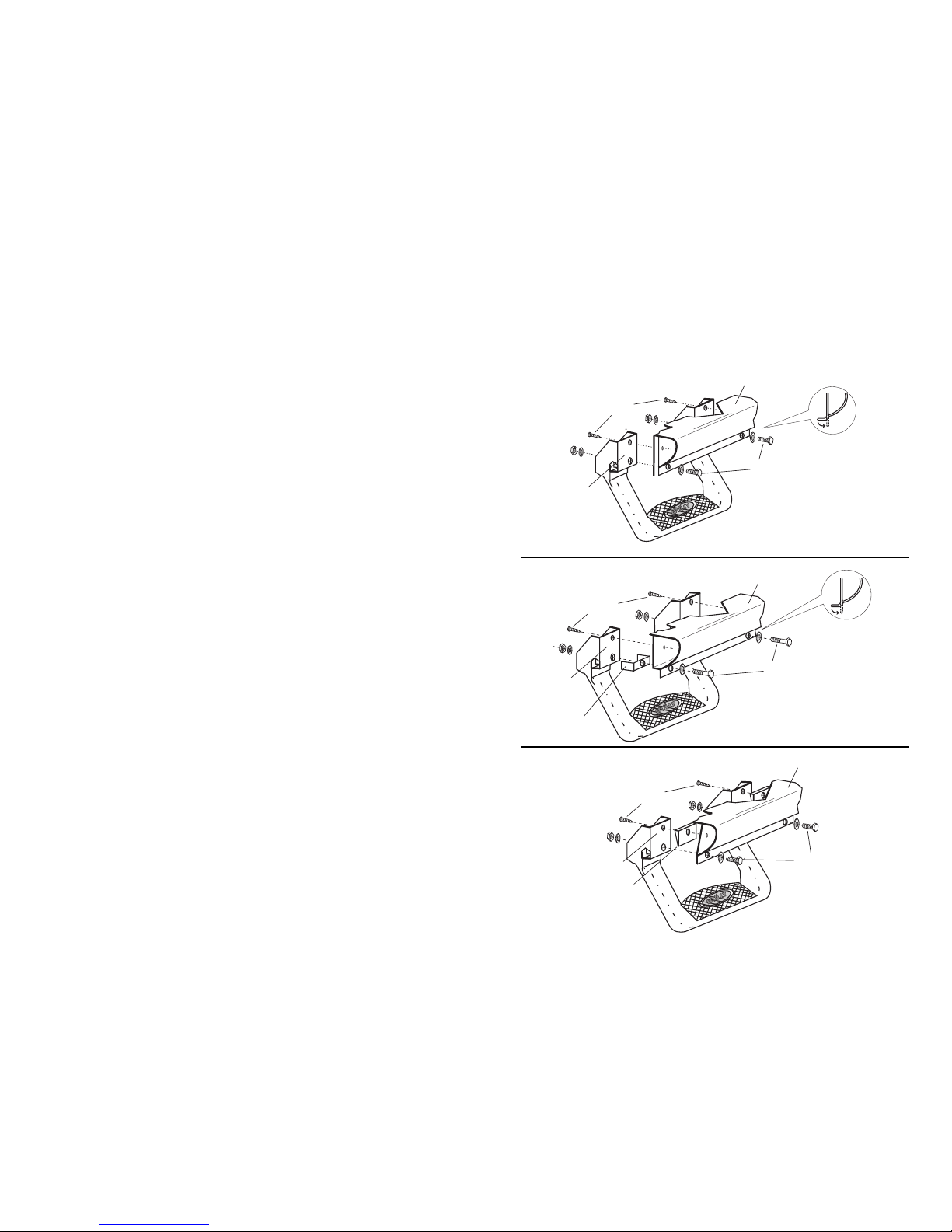
1. Examinez les illustrations pour le groupe E à la page suivante (voir les figures E-2 et E-4)
pour identifier celle qui correspond à votre véhicule.
2. Si la plaque de montage n’atteint pas le bas de caisse, utilisez le support en C fourni
pour l’installation.
3. Placez le marchepied en position et tracez une ligne verticale au centre du marchepied
sur le rebord du joint de soudure du bas de caisse. Mesurez une distance de 4 1/16 po de
chaque côté de la ligne que vous avez tracée et faites un repère de ces points sur le rebord
du joint de soudure. La distance qui sépare ces deux points extérieurs devrait être de 8 1/8 po.
4. À partir des lignes externes, mesurez une distance de 1/2 po vers l’intérieur (1/4 po pour
le modèle Suburban) à partir du rebord intérieur du joint de soudure et faites un repère sur
chacune des deux lignes. Pour de meilleurs résultats, servez-vous d’un pointeau et d’un
foret de 1/8 po pour percer un avant-trou. Percez ensuite un trou de 3/8 po à ces deux points.
Important : Assurez-vous que la zone à percer est exempte de toute obstruction
(p. ex., conduites de climatisation et faisceaux de fils) (voir les figures E-3 et E-4).
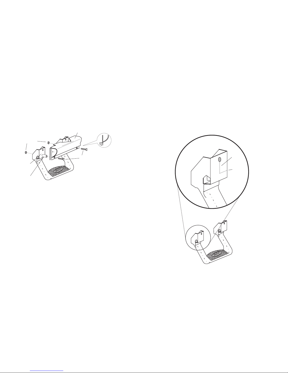
5. Placez le support en C contre le bas de caisse (voir les figures E-1 et E-3). Acheminez
délicatement les supports jusqu’à leur position. Faites un repère sur le support en C à travers
le trou de 3/8 po que vous avez percé sur le rebord du joint de soudure. Enlevez le support
et percez un trou de 3/8 po au point marqué.
6. Fixez les supports en C au marchepied en insérant les vis à tôle de 1 po dans les trous
supérieurs pratiqués dans le marchepied et dans les petits trous pratiqués dans les supports
en C. Assurez-vous que les supports sont alignés avec les rebords du marchepied.
Remarque : Si le trou inférieur du support en C n’est pas aligné, il suffit de fléchir vers
l’intérieur le support jusqu’à ce que le trou inférieur soit centré à environ 3/8 po vers le haut du
marchepied. Faites un repère sur le marchepied à travers le trou inférieur des supports.
Enlevez les supports du marchepied et vérifiez la distance entre les deux points marqués
sur le marchepied, qui devrait être de 8 1/8 po.
7. Percez un trou de 3/8 po aux points marqués du marchepied.
8. Remettez les supports en C à leur position de montage. Insérez le boulon de 5/16 po avec
la rondelle correspondante dans les trous de 3/8 po du joint de soudure (voir le n° 1 de la
figure E-2). Remarque : Si les trous ne s’alignent pas, limez-les de sorte que le boulon
puisse être inséré librement dans la carrosserie et le support. Ne serrez pas les boulons
maintenant. Tenez solidement le support en place et faites un repère sur la carrosserie du
véhicule à travers le trou supérieur du support en C. Retirez les supports en C de leur
position de montage.
9.En vous reportant à la figure E-5, enlevez la plaque en plastique du seuil de porte et
déplacez le faisceau de fils en prévision du perçage.
10.Percez un trou de 1/8 po aux points de la carrosserie que vous avez marqués à l’étape 8.
Assurez-vous que tous les fils sont bien éloignés.
INSTRUCTIONS D’INSTALLATION POUR LE GROUPE E :
1. Repérez un bon endroit pour monter le marchepied. Remarque : Pour un bon ajustement,
le centre du marchepied doit être aligné avec le rebord avant de l’armature du siège et la plaque
de montage du marchepied doit pouvoir reposer à plat sur le bas de caisse.
2. Placez le marchepied en position et tracez une ligne verticale au centre du marchepied sur
le rebord du joint de soudure du bas de caisse. Mesurez une distance de 4 1/16 po de chaque
côté de la ligne que vous avez tracée et faites un repère de ces points sur le rebord du joint de
soudure. La distance qui sépare ces deux points extérieurs devrait être de 8 1/8 po.
3. Percez un trou de 3/8 po à ces points. Avant de percer un trou de 3/8 po sur le rebord, pour
de meilleurs résultats, servez-vous d’un pointeau et d’un foret de 1/8 po pour percer un
avant-trou. Important : Assurez-vous que la zone à percer est exempte de toute obstruction
(fils, canalisations de carburant, conduites de frein, etc.).
4. Alignez les trous de montage du marchepied aux trous de 3/8 po que vous avez percés sur
le rebord. En utilisant les boulons de 5/16 po x 1 1/8 po avec les écrous et les rondelles
correspondants, montez le marchepied à la carrosserie et serrez les fixations à la main
pour l’instant (voir la figure D). Si les boulons de 1 1/8 po ne s’insèrent pas en ligne droite,
vous devrez peut-être vous servir d’une petite lime ronde pour agrandir l’ouverture.
5. À l’aide d’un foret de 1/8 po, percez un trou dans la carrosserie en utilisant comme
guide le trou supérieur de 1/4 po pratiqué dans le marchepied. Posez les vis à tôle de
1 po dans les trous supérieurs et serrez-les. Serrez ensuite tous les boulons déjà
posés pour compléter l’installation.
INSTRUCTIONS D’INSTALLATION POUR LE GROUPE D :
Carrosserie
Boulon
de 1 1/8 po
Figure D
Vis à tôle
Trou de
montage
de l’ancrage