manuals.online logo
Brands
  1. Home
  2. •
  3. Brands
  4. •
  5. Thitronik
  6. •
  7. Automobile Accessories
  8. •
  9. Thitronik WiPro III safe.lock User manual

Thitronik WiPro III safe.lock User manual

1
Updated 05/22
WiPro III safe.lock
Installation Manual Fiat Ducato 8
(Model year 2022+)
Disclaimer:
This installation manual is intended for
professional service companies. Appropri-
ate background knowledge about work on
vehicle electrics and electronics is there-
fore required.
Improper interventions into the vehicle
electronics and their components can un-
der certain circumstances cause them to
no longer function as intended. This can
considerably endanger the installer (work,
e.g., on the airbag system) and the road-
worthiness of the vehicle and can result
not only in property damage, but also in
personal injury.
Therefore, have all work on the vehicle
electronics carried out by a qualified shop.
Thitronik GmbH is not liable for damage to
property and/or personal injury resulting
from improper, incorrect or only partially
completed installation work. The installing
service company is obligated to ensure
that its connection work neither is faulty
in itself nor can lead to faults or dangers
on the vehicle.
The instructions in the WiPro installation
manual remain applicable. Unused inputs
and outputs must be isolated.
Should the given vehicle conditions differ
from those described herein, please con-
tact the manufacturer or our technical
support team.
WiPro III safe.lock Installation Manual – Fiat Ducato 8 and identical from model year 2022)2
We recommend a check of the vehicle
conditions:
1. Is a wireless remote control available
for the vehicle and is it working?
It may only be necessary to insert a
button cell to get the vehicle to ‘flash’.
Then the WiPro can be activated/deac-
tivated with it (without safe.lock!).
2. Does the vehicle have a central locking
system and is it working?
3. Make sure that the check mark for
“Flashing lights when locking” is set in
the vehicle settings of the base vehicle.
This can be found in the central display
under Vehicle->Settings.
The menu items could be named
differently.
4. If the car has original doors, open doors
should be indicated on the speedome-
ter during ignition. With fully integrated
motorhomes, the doors/hatches are
also sometimes included on the CAN
bus. In such cases no wireless magnet
contact has to be used there.
5. Is the horn working? Does the vehicle
have electronic (e.g. warning lights,
fault memory) or electrical (e.g. lighting)
faults?
Aids/tools:
• WiPro III safe.lock from serial number
1050-018 Art.Nr. 101050)
• Additional wireless accessories or sirens
• Combination pliers / water pump pliers
• PH2 Phillips screwdriver and/or T25 star
screwdriver
• 10mm box spanner
• 3mm Allen key
• Cordless screwdriver with 8 mm drill bit
for status LED
Setting the CAN bus interface for vehicle
type Ducato:
1. Disconnect the power supply for the
WiPro and open the housing.
2. Set the DIP switch as follows:
3. Close the housing again and continue
with the installation.
1
↑
on
42 5 73 6 8
WiPro III safe.lock
WiPro III safe.lock Installation Manual – Fiat Ducato 8 and identical from model year 2022)3
Step 2: Dismantling of the on-board computer
• Exposed on-board computer
• Press the tab (marked yellow) slightly to the right,
the on-board computer can be lowered towards the driver‘s seat
Step 1: Remove the dashboard panelling
Remove the three screws (PH2 or T25) as shown in the photos.
Pull the panel towards the driver’s seat to remove it; also remove the small
storage compartment (an additional screw).
Later backup for
WiPro III (7.5, 10 or 15A)
→
WiPro III safe.lock Installation Manual – Fiat Ducato 8 and identical from model year 2022)4
Step 3: Adhere WiPro to on-board computer
Remove the cover strips on the self-adhesive pads on the WiPro III and adhere the system to the
on-board computer with the plug connection pointing to the driver’s door (to the left).
Step 4: Make electrical connection to earth (terminal 31)
The next earthing point is on the left in the extension of the A-pillar. Remove the nut (M10),
leaving the original ring eyelets in place, and add the black wire from the WiPro III.
Then put the nut back on and tighten!
WiPro III safe.lock Installation Manual – Fiat Ducato 8 and identical from model year 2022)5
Step 5: Make electrical connection to CAN and flashing warning lights
Remove the larger connector on the rear side of the on-board computer (red mark-
ing in figure). Pull out the plug inserts to access the wires. Make the connections
according to the pinout with the blue gel-filled branch connectors:
Pinout for Fiat Wire colour for Fiat Cable colour on WiPro III Function
Pin 59 violet/orange →red/pink flashing warning
lights
Step 6: Make electrical connection to 12 V (30) and ignition (15)
Remove the smaller plug on the back of the on-board computer (green marking in the
figure). Pull the insert out of the plug to access the cables.
Make connections with blue, gel-filled branch connectors:
Pinout for Fiat Wire colour for Fiat Cable colour on WiPro III Function
Pin 18 red/green → red (terminal 30)
Pin 17 blue/grey →yellow (terminal 15)
Replace both inserts and provide strain relief again via cable tie.
Due to the removal of the small connector, the Fiat clock has to be reset.
WiPro III safe.lock Installation Manual – Fiat Ducato 8 and identical from model year 2022)6
Step 7: safe.lock control of central locking system and CAN-BUS
On-board computer back in place; remove green connector on the lower left. Pull the
insert out of the plug to access the cables. Make connections with blue, gel-filled
branch connectors:
Pinout for Fiat Wire colour for Fiat Cable colour on WiPro III Function
Pin 9 blue/yellow → blue/black central locking system front
Pin 41 grey/white → blue central locking system rear
Pin 42 white → violet/orange CAN
Pin 43 blue → white/orange CAN
Possible errors in the central locking system at the end of installation:
Error: All doors can be locked, but they cannot be unlocked at the front or the rear.
Solution: Blue and blue/black wires mixed up – check and change connection if
necessary.
Error: All doors can be locked, but they can only be unlocked at the front.
Solution: Blue wire has no or incorrect connection – check and fix.
Error: Doors cannot be locked:
Solution: Blue/black wire has no connection – check/fix.
WiPro III safe.lock Installation Manual – Fiat Ducato 8 and identical from model year 2022)7
Step 8:
Make electrical connection to vehicle horn
Remove steering column cover panel (four
screws, 3mm Allen key). Black connector
(see red circle): strip about 10 cm of insula-
tion off of the wiring harness directly under
the steering wheel. (Caution! Air bag wires
are also present.) Then connect with the
blue gel-filled branch connector. This wire
is at 0 V when the horn button is pressed;
otherwise 12 V can be measured there.
Wire colour for
Fiat Cable colour on
WiPro III Function
green/white
(Pin 9) → pink horn
Step 9: Install status LED
The customer may want a different posi-
tion – please clarify this beforehand.
Drill an 8mm hole, insert the LED and
reconnect the red/black wire of the LED
with a white connector to the counterpart
on the WiPro III cable set.
Step 10: Teach in wireless accessories
All wireless accessories (including the
components included with the central
control unit) must be taught in on the
WiPro III once. The accessories must bear
the extension ‘868’ – this is the frequen-
cy in MHz.
1. Press the button to the right of the
connector and hold it down until the
system beeps. The status LED is con-
tinuously lit.
2. Now activate each wireless magnetic
contact 868, handheld radio transmit-
ter 868 and radio cable loop 868 as
well as wireless gas alarm 868 to be
stored several (2–3) times: to do so,
move the magnets more than 30 mm
away from the transmitter unit, press
the handheld radio transmitter buttons,
switch on the gas alarm and take the
cable loop out of the holder. Successful
storing is acknowledged through a beep
and the LED goes out briefly.
3. To end the teach-in mode, briefly
disconnect the system or press the
button on the WiPro.
The memory is not volatile, so long-term
interruption of the power supply is also
possible. Even in this case, the accesso-
ries remain stored.
Should deletion be necessary, please
refer to the section ‘Deleting wireless
components’ in the installation manual.
WiPro III safe.lock Installation Manual – Fiat Ducato 8 and identical from model year 2022)8
Step 11: Mount the wireless accessories
Install the wireless magnetic contacts, taking into account the attached installation instructions.
Install the wireless gas alarm and radio cable loop according to the corresponding instructions.
Step 12: Final function test
Test original remote control / vehicle doors.
1. The „lock“ button on the original vehicle remote control arms the system. If you hear a series
of short beeps when locking, one of the taught-in magnetic contacts is open. However, the
system armed anyway.
After installation, it may be necessary to lock and unlock several times until the system reacts,
as the CAN bus data must first be synchronized.
The control center acknowledges activation with a beep and the direction indicators flash.
The status LED flashes.
If a driver‘s door is open, the vehicle does not lock (vehicle‘s own function) and the system is
not activated.
2. Trigger the alarm by mechanically opening the driver‘s door - unlock from the inside with the
door handle or from the outside with the mechanical key and open the door.
3. The acoustic alarm sounds for approx. 30 seconds. The visual alarm lasts approx. 180 seconds.
4. The “unlock” button disarms the system or interrupts the alarm.
Test Thitronik wireless accessories
1. The Thitronik handheld radio transmitter 868 activates/deactivates the system through the
corresponding pressing of the buttons. Depending on the setting of jumper 6, this occurs with
or without an acknowledgement tone from the WiPro.
(See Section 1.2 of the operating manual.)
2. Holding both buttons down for about one second activates the panic alarm.
With this WiPro variant (safe.lock), the central locking system locks in parallel to arming and
unlocks upon disarming. The complete central locking system is always actuated
(front and rear together)!
3. The wireless magnetic contacts trigger an alarm with an armed WiPro and opening.
(see Section 1.9.1 of the operating manual)
4. Arming the WiPro with one or more opened contacts triggers the vent function: Repeated
signal tones followed by the ‘armed’ signal tone. The opened wireless magnetic contacts are
excluded from the alarm. They become active again approx. four seconds after being closed.
(See Section 1.4 of the operating manual.)
5. The wireless gas alarm needs approx. four minutes of pre-running. Once its LED is flashing
green, it detects, e.g., lighter gas for test purposes. The alarm can be triggered with an armed
or disarmed WiPro. The acoustic alarm sounds with pauses.
(see Section 1.9.2 of the operating manual)
6. The radio cable loop reports the removal from the holder. To test, press gently on the lower
edge and take the device out upwards.
(see Section 1.9.8 of the operating manual)
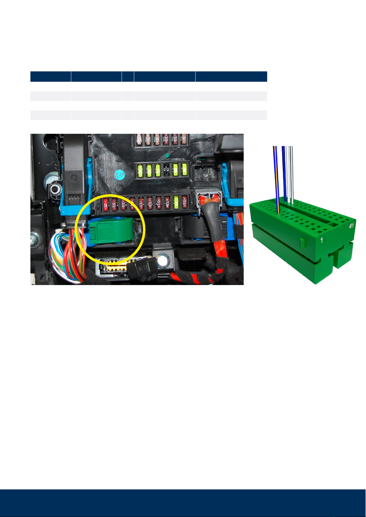
We recommend making a note of the corresponding fuse in the installation manual for the user.
Entering the serial number of the WiPro in one of the two manuals is also helpful for later clarifica-
tion, e.g. in case of questions.
WiPro III safe.lock Installation Manual – Fiat Ducato 8 and identical from model year 2022)9
Possible mistakes
Failure:
The system does not react to the commands from the remote control key, but emits a
beep when the power supply is applied.
Solution:
1. Check CAN connection (white/orange and purple/orange).
2. Shortly pressing the button on the circuit board activates the diagnostic mode.
If the radio key is operated or another process generates data traffic on the CAN
bus, this is indicated by the status LED flickering. If no data traffic is displayed, the
bus is inactive or the connection is incorrect.
3. Make sure that the check mark for “Flashing lights when locking” is set in the vehicle
settings of the base vehicle. This can be found in the central display under Vehi-
cle->Settings.
The menu items could be named
differently.
Failure:
The system does not react to the commands from the remote control key and does not
emit a beep when the power supply is applied.
Solution
:
1. Check power supply.
2. Correct pin assigned on the front connector?
3. Is the „crimp-connection“ carried out correctly?
4. Ignition switched on? When the ignition is active, the system is deactivated.
5. Is the fuse (see step 2 on page 3) present and intact?
Failure:
All contacts are closed. Nevertheless, an open contact is signaled when arming.
Solution:
1. Check the distance between the transmitter and the magnet.
2. Open and close all contacts several times, then arm again.
3. Open contact is still signaled
> Pull the plug for the power supply when the contacts are closed or remove the
fuse (see step 2 on page 3)
> Restore the power supply.
10
Mounting of wireless magnetic contacts
868 to windows, doors, hatches etc.
Item no.: 100757, 100758
11
2. The circuit board is inserted into the transmitter housing (transmitter LED oriented upwards pointing away from
magnet) and the transmitter cover is snapped on.
The circuit board must not be
aligned with the transmitter LED
pointing towards the magnet!
If it is, then teach-in, but no alarm, will be possible.
Reed switch
Transmitter LED
Magnet
1. The orientation of the transmitter housing on the window frame depends on the available space (frame profile,
distance to the roller blind or window).
Variant lying
left
Window frame
Windowpane
Transmitter housing
Magnet Magnet
Window frame
Windowpane
Transmitter housing
Variant lying
right
Magnet
Window frame
Transmitter LED
Windowpane
Transmitter housing
Reed switch
Battery
Variant lying left
Magnet
Window frame
Windowpane
Transmitter LED
Transmitter housing
Reed
switch
Variant lying right
Battery
12
Variant upright
Windowpane
Windowpane
Variant
windowpane
Should upright mounting on the window
frame or mounting on the windowpane
be necessary, e.g., for space reasons,
the transmitter LED must also be aligned
pointing away from the magnet.
Alternative mounting variants
Door or hatch mounting
Ideally, the transmitter housing is aligned and
fixed on the frame and the magnet is attached
to the door leaf or the hatch. The specifica-
tions in the section ‘Positioning the magnet’
must be observed.
The circuit board must not be aligned
with the transmitter LED pointing to-
wards the magnet! If it is, then teach-
in, but no alarm, will be possible.
For bridging larger distances to
hatches or for optimal alignment of
the transmitter antenna, the use of
mounting adaptors (art. no. 100428,
100729) is recommended.
Fixing options
The wireless magnetic contacts are ideally
mounted with the help of the supplied adhe-
sive pads.
The mounting surface must be clean, dry and
grease-free. Please pretreat with a suitable
cleaning agent
as the wireless magnetic contacts may fall off
and thus unexpectedly trigger an alarm after
weeks or months of operation.
Do not process at temperatures below 15 °C.
The adhesive pads only reach their ultimate
strength after approx. 24 hours.
Should mounting with the adhesive pads not
be possible (e.g. to a door or hatch), screw
fixing is also possible. The corresponding
markings can be found on the inside of the
transmitter housing.
13
Transmitter
LED
Reed switch
Transmitter housing
Transmitter cover
Battery
Battery Battery
Long housing leg
Short housing leg
Top view of
circuit board
Bottom view of
circuit board
Cross section
Battery
Magnet
22-30mm
Positioning the magnet
As long as the magnet is in the yellow area, its
magnetic field keeps the reed switch closed. If the
magnet moves from there into the blue area, the
reed switch is opened and a transmission opera-
tion is triggered (transmitter LED flashes). With an
armed alarm system, this leads to an alarm.
The magnet should not be mounted past the red
line and should later only move between the yellow
and blue areas.
The orientation of the transmitter housing (long leg/
short leg) is not important in this representation.
Alignment of circuit board in transmitter housing
(as-delivered condition) and positions of components.

Other Thitronik Automobile Accessories manuals

Thitronik WiPro III User manual

Thitronik

Thitronik WiPro III User manual

Thitronik WiPro III User manual

Thitronik

Thitronik WiPro III User manual

Popular Automobile Accessories manuals by other brands

Cruz Airo R Assembly instructions

Cruz

Cruz Airo R Assembly instructions

Yakima LOCKN'LOAD FIRST TIME INSTALLATION

Yakima

Yakima LOCKN'LOAD FIRST TIME INSTALLATION

Spike 58-4250 quick start guide

Spike

Spike 58-4250 quick start guide

QA1 52363 installation instructions

QA1

QA1 52363 installation instructions

Compass 238 280 instruction manual

Compass

Compass 238 280 instruction manual

Classic Accessories RV Ladder Cover Instructions & Care

Classic Accessories

Classic Accessories RV Ladder Cover Instructions & Care

Curt Group 3025101 installation manual

Curt Group

Curt Group 3025101 installation manual

Tesla HOME CONNECTOR user manual

Tesla

Tesla HOME CONNECTOR user manual

BASETech KUC-1000 operating instructions

BASETech

BASETech KUC-1000 operating instructions

OMT SW-5928 User's installation guide

OMT

OMT SW-5928 User's installation guide

Acewell ACE-27 series user manual

Acewell

Acewell ACE-27 series user manual

Westin 22-1775 instructions

Westin

Westin 22-1775 instructions

GReddy 12529001 instruction manual

GReddy

GReddy 12529001 instruction manual

EUFAB CROW BASIC operating instructions

EUFAB

EUFAB CROW BASIC operating instructions

MVG 2040 F owner's manual

MVG

MVG 2040 F owner's manual

Mynew Portable Car Umbrella user guide

Mynew

Mynew Portable Car Umbrella user guide

Nav TV GVIF-CTS manual

Nav TV

Nav TV GVIF-CTS manual

Navman N-series B2+ user manual

Navman

Navman N-series B2+ user manual

manuals.online logo
manuals.online logoBrands
  • About & Mission
  • Contact us
  • Privacy Policy
  • Terms and Conditions

Copyright 2025 Manuals.Online. All Rights Reserved.