manuals.online logo
Brands
  1. Home
  2. •
  3. Brands
  4. •
  5. Cessna
  6. •
  7. Aircraft
  8. •
  9. Cessna 750 User manual

Cessna 750 User manual

Other manuals for 750

2

Other Cessna Aircraft manuals

Cessna Skyhawk 1970 User manual

Cessna

Cessna Skyhawk 1970 User manual

Cessna 150 1968 User manual

Cessna

Cessna 150 1968 User manual

Cessna 1971 Super Skymaster User manual

Cessna

Cessna 1971 Super Skymaster User manual

Cessna 1973 177 User manual

Cessna

Cessna 1973 177 User manual

Cessna 172 P Technical specifications

Cessna

Cessna 172 P Technical specifications

Cessna 680 User manual

Cessna

Cessna 680 User manual

Cessna 1980 182Q Technical specifications

Cessna

Cessna 1980 182Q Technical specifications

Cessna Skywagon 185 User manual

Cessna

Cessna Skywagon 185 User manual

Cessna 172S Skyhawk User manual

Cessna

Cessna 172S Skyhawk User manual

Cessna 182 User manual

Cessna

Cessna 182 User manual

Cessna 150 STANDARD User manual

Cessna

Cessna 150 STANDARD User manual

Cessna 1978 Skyhawk 172N Manual

Cessna

Cessna 1978 Skyhawk 172N Manual

Cessna 182 Installation guide

Cessna

Cessna 182 Installation guide

Cessna 1978 Skyhawk 172N User manual

Cessna

Cessna 1978 Skyhawk 172N User manual

Cessna 152 1978 Owner's manual

Cessna

Cessna 152 1978 Owner's manual

Cessna 172 Skyhawk SERIES Installation guide

Cessna

Cessna 172 Skyhawk SERIES Installation guide

Cessna Skyhawk 172N 1980 Owner's manual

Cessna

Cessna Skyhawk 172N 1980 Owner's manual

Cessna 152 Quick setup guide

Cessna

Cessna 152 Quick setup guide

Cessna 152 Installation guide

Cessna

Cessna 152 Installation guide

Cessna Grand Caravan 208B G1000 User manual

Cessna

Cessna Grand Caravan 208B G1000 User manual

Cessna A150M Owner's manual

Cessna

Cessna A150M Owner's manual

Cessna Hawk XP Owner's manual

Cessna

Cessna Hawk XP Owner's manual

Cessna 172R User manual

Cessna

Cessna 172R User manual

Cessna SKYMASTER 336 1964 User manual

Cessna

Cessna SKYMASTER 336 1964 User manual

Popular Aircraft manuals by other brands

Skywalk Mescal 4 instruction manual

Skywalk

Skywalk Mescal 4 instruction manual

Cirrus SR22 Maintenance manual

Cirrus

Cirrus SR22 Maintenance manual

Schleicher ASK 21 Assembly & Disassembly

Schleicher

Schleicher ASK 21 Assembly & Disassembly

Cirrus SR20 Maintenance manual

Cirrus

Cirrus SR20 Maintenance manual

Skywalk Tequila 2 Manual/service

Skywalk

Skywalk Tequila 2 Manual/service

MAULE M-7-235B Airplane Flight Manual

MAULE

MAULE M-7-235B Airplane Flight Manual

Tecnam P92 Echo Super Maintenance manual

Tecnam

Tecnam P92 Echo Super Maintenance manual

Wills Wing HP II Owner's and service manual

Wills Wing

Wills Wing HP II Owner's and service manual

MAULE MX-7-180B Airplane Flight Manual

MAULE

MAULE MX-7-180B Airplane Flight Manual

Ozone ZENO 2 Pilot's manual

Ozone

Ozone ZENO 2 Pilot's manual

Boeing 737 Quick reference handbook

Boeing

Boeing 737 Quick reference handbook

MHD MHDFLY TINY GLIDER Z5630 Manual and using instructions

MHD

MHD MHDFLY TINY GLIDER Z5630 Manual and using instructions

Ozone Roadster Pilot's manual

Ozone

Ozone Roadster Pilot's manual

SpeedWing Mini SpeedWing EX Assembly instructions

SpeedWing

SpeedWing Mini SpeedWing EX Assembly instructions

Daher-Socata TBM 900 Pilot's information manual

Daher-Socata

Daher-Socata TBM 900 Pilot's information manual

Aircraft REIMS F152 Flight manual

Aircraft

Aircraft REIMS F152 Flight manual

Dudek NEMO2 user manual

Dudek

Dudek NEMO2 user manual

Pipistrel ALPHA Trainer Operator's manual

Pipistrel

Pipistrel ALPHA Trainer Operator's manual

manuals.online logo
manuals.online logoBrands
  • About & Mission
  • Contact us
  • Privacy Policy
  • Terms and Conditions

Copyright 2025 Manuals.Online. All Rights Reserved.

CESSNA AIRCRAFT COMPANY
AIRCRAFT DIVISION
WICHITA, KANSAS 67277
Magnetometer Relocation
ICA Supplement
MODEL NO: 750
SUPPLEMENT NO: ICA-750-34-00002
SUPPLEMENT DATE: 11/20/2014
© Cessna Aircraft Company
Form 2261 Rev 1
CESSNA AIRCRAFTCOMPANY
AIRCRAFT DIVISION
WICHITA, KANSAS 67277
REVISIONS
ICA-750-34-00002 Rev: - Date: 11/20/2014
ICA Summary Pages 1-6
Manuals Affected Description Title
Maintenance Manual 34-15-00 pages
1-3
STANDBY INSTRUMENTS - DESCRIPTION AND
OPERATION
• Updates the location where the magnetometer is installed.
Maintenance Manual 34-15-20 pages
401-403
L-3 COMMUNICATIONS MAG-3000 MAGNETOMETER
- REMOVAL/INSTALLATION
• Updates the location where the magnetometer is installed.
Appendix A: Illustrated Parts
Catalog
NOT USED
Appendix B: Wiring Diagram
Manual
NOT USED
1. Export Compliance
A. This publication contains technical data and is subject to U.S. export regulations. This information has
been exported from the United States in accordance with export administration regulations. Diversion
contrary to U.S. law is prohibited.
ECCN: 9E991
2. Revision Bars
A. Revision bars in this ICA supplement identify new ICAs and/or changes to the current ICAs in the
released maintenance manual.
• New ICAs that are not in the current maintenance manual will have a revision bar from top to
bottom along the left margin.
• ICAs that are in the current maintenance manual and have information added, deleted or revised
will have a revision bar(s) in the left margin adjacent to the added, deleted or revised information.
• New or changed illustrations will have a change bar for the entire length of the page.
3. Page Numbering
A. The page number system for ICA included in this supplement have three-element numbers that are
separated by dashes. The three-element number is found at the bottom right corner of the page, left
of the page number. The date is found below the page number.
B. When the chapter/system element number is followed with zeros in the section/subsystem and
subject/unit element number (28-00-00), the information is applicable to the entire system.
Page 1 of 6
Nov 20/2014
© Cessna Aircraft Company
ICA-750-34-00002 Form 2261 Rev 1
CESSNA AIRCRAFT COMPANY
AIRCRAFT DIVISION
WICHITA, KANSAS 67277
C. When the section/subsystem element number is followed with zeros in the subject/unit element
number (28-21-00), the information is applicable to the subsystems in the system.
D. The subject/unit element number is used to identify information applicable to units in the subsystems.
The subject/unit element number continues in sequence from the number -01- with the number of
subsystem units in which maintenance information is necessary.
E. All system/subsystem/unit (chapter/section/subject) maintenance data is separated into specified
types of information: Description and Operation, Troubleshooting, Maintenance Practices, etc.
Blocks of page numbers that are in sequence are used to identify the type of information:
(1) Description and Operation or Troubleshooting information may not be included if the procedure
is easy. When subtopics are short, they may be put together into the Maintenance Practices
section. Maintenance Practices can have a mix of subtopics that includes information to service,
remove, install, adjust, test, clean, paint or do approved repairs.
(2) Longer procedures that are not as easy to do may be included in a specified section.
Page 1 through 99 - Description and Operation
Page 101 through 199 - Troubleshooting
Page 201 through 299 - Maintenance Practices
Page 301 through 399 - Servicing
Page 401 through 499 - Removal/Installation
Page 501 through 599 - Adjustment/Test
Page 601 through 699 - Inspection/Check
Page 701 through 799 - Cleaning/Painting
Page 801 through 899 - Approved Repairs
F. A typical page number:
G. Illustrations use the same figure numbers as the page block in which they appear. For example, Figure
202 would be the second figure in a Maintenance Practices section.
4. Supplement Revisions
A. Revisions to this supplement may be accomplished if changes to this supplement are required after
release of the original issue and prior to incorporation into the manuals listed in the REVISIONS table.
B. All revisions to this supplement will have changes identified in detail in the revision block(s) above.
C. All pages in this ICA supplement will have the same date and are valid as of the date shown.
Page 2 of 6
Nov 20/2014
© Cessna Aircraft Company
ICA-750-34-00002 Form 2261 Rev 1
CESSNA AIRCRAFTCOMPANY
AIRCRAFT DIVISION
WICHITA, KANSAS 67277
5. ICA Incorporation into Applicable Manuals
NOTE: Most ICA supplements will be incorporated in the next available revision to the manuals listed
above and should be used in conjunction with those manuals until the next available revision is
released.
A. The ICA Supplement List located in the Introduction section of each manual listed in the REVISIONS
table will indicate the incorporation status as of the release date of the published revision.
B. The manual revision level of the supplement incorporation will be listed in the "Manual Incorporation
Status" column in the ICA Supplement List, when those ICAs associated with that manual have been
incorporated. After ICAs are incorporated, the manual that they are incorporated in must now be used
for those ICAs instead of the supplement.
• Based on revision cycle times for the affected manuals, MM ICAs, WDM ICAs, etc. in this
supplement may be incorporated in the manuals at different times.
• There will not be a revision to this supplement to indicate incorporation in the manuals. Users are
required to check the ICA Supplement List for each manual affected to determine incorporation
status.
C. This supplement will be completely superseded by the manuals listed in the REVISIONS table when
it has been incorporated in all of the manuals.
Page 3 of 6
Nov 20/2014
© Cessna Aircraft Company
ICA-750-34-00002 Form 2261 Rev 1
CESSNA AIRCRAFT COMPANY
AIRCRAFT DIVISION
WICHITA, KANSAS 67277
INTRODUCTION
1. Purpose
A. The purpose of this Supplement is to provide the maintenance technician with the information
necessary to ensure the correct functionality and performance of the Magnetometer Relocation on
the Cessna Model 750 until this information gets incorporated into the next revision to the manuals
listed in the "REVISIONS" section of this supplement.
B. This ICA supplement is designed to satisfy the requirements of 14 CFR 25.1529 "Instructions for
Continued Airworthiness" associated with this installation. This document is a supplement to the
Model 750 Maintenance Manual and will be incorporated in the next revision to the manual.
C. When this information is incorporated in the next revision to the manuals listed in the "REVISIONS"
section, those manuals shall take precedence over this supplemental document. Refer to the "ICA
Supplement List" in the "Introduction" section of the respective manual for the status of all applicable
ICA Supplements.
D. Revisions to this supplement may occur if there is a change to any of the ICAs in this supplement
prior to incorporation into all of the affected manuals.
NOTE: This document must be placed with the aircraft operator's Technical Library CD-ROM
or Model 750 Maintenance Manual and incorporated into the operator's scheduled
maintenance program.
2. Effectivity
A. These Instructions for Continued Airworthiness (ICA) are effective for the following aircraft model and
serialization.
Model Beginning Effectivity Ending Effectivity
750 -0501 and On.
3. Complete ICA Documents
A. The following document(s), in conjunction with this supplement, constitute the Instructions for
Continued Airworthiness for the Magnetometer Relocation on the Cessna Model 750. All items must
be available to the operator at initial delivery.
(1) Model 750 (0501 & On) Maintenance Manual
(2) Model 750 (0501 & On) Wire Diagram Manual
4. System Components
A. Refer to Appendix A: Illustrated Parts Catalog
Page 4 of 6
Nov 20/2014
© Cessna Aircraft Company
ICA-750-34-00002 Form 2261 Rev 1
CESSNA AIRCRAFTCOMPANY
AIRCRAFT DIVISION
WICHITA, KANSAS 67277
LIST OF INSTRUCTIONS FOR CONTINUED AIRWORTHINESS
1. Model 750 Maintenance Manual
A. Chapter 34 Navigation
(1) Refer to 34-15-00, Standby Instruments - Description and Operation
(2) Refer to 34-15-20, L-3 Communications MAG-3000 Magnetometer - Removal/Installation
Page 5 of 6
Nov 20/2014
© Cessna Aircraft Company
ICA-750-34-00002 Form 2261 Rev 1
CESSNA AIRCRAFT COMPANY
AIRCRAFT DIVISION
WICHITA, KANSAS 67277
INSPECTION PROGRAM AND AIRWORTHINESS LIMITATIONS
1. Continuous Inspection Program
A. This ICA Supplement does not affect the current inspection program.
2. Airworthiness Limitations
A. Cessna Aircraft Company Model 750 (0501 & On) Maintenance Manual, Chapter 4, Airworthiness
Limitations, contains the system and airframe limitations for the Model 750.
NOTE: The Airworthiness Limitations section is FAA-approved and specifies maintenance
required under Section 43.16 and 91.403 of Title 14 Code of Federal Regulations, unless
an alternative program has been FAA approved.
(1) There are no new (or additional) airworthiness limitations associated with this equipment and/or
installation.
Page 6 of 6
Nov 20/2014
© Cessna Aircraft Company
ICA-750-34-00002 Form 2261 Rev 1
CESSNA AIRCRAFT COMPANY
MODEL 750 (SERIAL -0501 AND ON)
MAINTENANCE MANUAL
STANDBY INSTRUMENTS - DESCRIPTION AND OPERATION
1. General
A. This section gives a description and the operation of the standby instrument system. The line
replaceable units (LRU's) in the standby instrument system are the L-3 Communications GH-3900
Secondary Flight Display (SFD), L-3 Communications GH-3900 Detachable Configuration Module
(DCM), L-3 Communications ADC-4000 Standby Air Data Computer (ADC), L-3 Communications
MAG-3000 Magnetometer, standby pitot probe, standby static port, and standby emergency power
supply.
B. Refer to Figure 1 for a general view of the standby instrument system.
2. Description
A. L-3 Communications GH-3900 Secondary Flight Display (SFD)
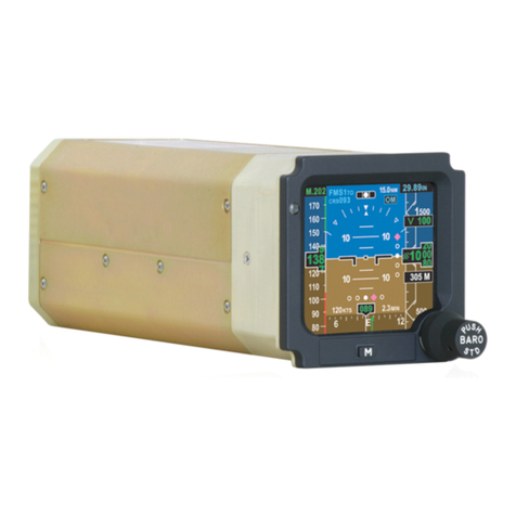
(1) The SFD is installed in the instrument panel in the cockpit, above the Garmin GDU 1400W
Multifunction Display (MFD).
(2) The SFD has two controls on its face, a BARO knob and an M button. The M button is used to
select or adjust the SFD Menu functions.
(3) The SFD unit is a stand-alone unit that has inertial sensors that give attitude data on an active
matrix color liquid crystal display (AMLCD) screen. Also, it shows:
• Altitude and airspeed data received from the standby air data computer (ADC) through an
ARINC 429 data bus
• Magnetic heading data received from the MAG-3000 Magnetometer through an RS-422
data bus and the internal inertial sensors
• Navigational data received from the Garmin G5000 avionics system through an RS-422
data bus.
(4) Electrical power to the SFD is supplied by the airplane's electrical system. If the airplane's
electrical power is not available, the standby emergency power supply in the nose compartment
will supply the electrical power.
B. L-3 Communications GH-3900 Detachable Configuration Module (DCM)
(1) The DCM is attached to the wiring harness at the rear of the SFD.
(2) The DCM has sufficient memory to record data that is special to the hardware and software
configurations for each installation, such as panel angle, navigation interface, aircraft heading
calibration, and display format. When the SFD is removed from the airplane, the DCM stays
connected to the airplane wiring harness. When the DCM is connected to a new or different
SFD, it is not necessary to configure the unit.
C. L-3 Communications ADC-4000 Standby Air Data Computer (ADC)
(1) The standby ADC is installed on the right side of the airplane, behind the refreshment center,
at approximately FS 150.00. An electrical connector, pitot hose, and static tube connect to the
bottom of the ADC.
(2) The ADC receives pitot-static pressure from the standby pitot probe and the standby static ports.
It sends this data to the SFD through an ARINC 429 data bus.
D. L-3 Communications MAG-3000 Magnetometer
(1) The magnetometer is installed in the vertical stabilizer under the bullet fairing.
(2) The magnetometer is a three-axis magnetic sensor that converts magnetic field data into a digital
format. This digital data is sent to and shown on the SFD.
E. Standby Pitot Probe
(1) The standby pitot probe is installed on the right side of the airplane, behind the refreshment
center, at FS 150.00 and WL 127.08. A hose connects to the rear side of the pitot probe. The
pitot probe supplies pitot pressure to the standby ADC.
(2) The pitot probe is electrically heated. This prevents the formation of ice on the inlet port.
34-15-00 Page 1
© Cessna Aircraft Company Nov 20/2014
ICA-750-34-00002 Form 2261 Rev 1
CESSNA AIRCRAFT COMPANY
MODEL 750 (SERIAL -0501 AND ON)
MAINTENANCE MANUAL
Standby Instrument System
Figure 1 (Sheet 1)
34-15-00 Page 2
© Cessna Aircraft Company Nov 20/2014
ICA-750-34-00002 Form 2261 Rev 1