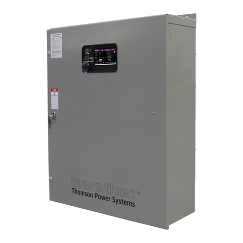
Thomson Power Systems TS 970 Service manual


TS 970 Transfer Switch
PM163 REV 0 20/02/05 1 Thomson Power Systems
TABLE OF CONTENTS
1. PRODUCT REVISION HISTORY 3
2. EQUIPMENT STORAGE 3
2.1. ENVIRONMENTAL CONDITIONS 3
3. NOTES TO INSTALLER 4
3.1. INSTALLATION CODES/PERMITS 4
3.2. APPLICATION 4
3.3. INSTALLATION LOCATION 4
3.4. POWER CABLING 5
3.5. CONTROL WIRING 5
3.6. GENERATOR SET AUTOMATIC OPERATION 5
3.7. LOAD TYPES 5
3.8. UPSTREAM OVER CURRENT PROTECTION 5
3.9. WITHSTAND/INTERRUPTING CURRENT RATINGS 6
3.10. TRANSFER SWITCHES WITH MULTI-TAP VOLTAGE CAPABILITY 6
3.11. REMOTE START CONTACT FIELD WIRING 6
3.12. DIELECTRIC TESTING 7
3.13. SEISMIC ANCHORING 7
4. GENERAL DESCRIPTION 10
4.1. TSC 900 ATS CONTROLLER 10
4.2. POWER CONTACTOR ATS 11
4.3. PRODUCT MODEL CODE 12
4.4. TYPICAL COMMISSIONING PROCEDURES 13
5. AUTOMATIC SEQUENCE OF OPERATION 13
5.1. STANDARD ATS - OPEN TRANSITION 13
5.2. TEST MODES 14

TS 970 Transfer Switch
PM163 REV 0 20/02/05 2 Thomson Power Systems
6. GENERAL NOTES ON SERVICING POWER CONTACTOR ATS 14
6.1. EQUIPMENT INSPECTION 14
6.2. RECOMMENDED MAINTENANCE 15
7. ATS MANUAL OPERATING INSTRUCTIONS 23
7.1. 100A –400A POWER CONTACTOR ATS MANUAL OPERATION 23
7.2. 600A –1200A POWER CONTACTOR ATS MANUAL OPERATION 26
8. ISOMETRIC VIEW - 3 / 4 POLE, 100A - 400A ATS (TYPICAL) 29
9. ISOMETRIC VIEW - 3 / 4 POLE, 600A - 1200A ATS (TYPICAL) 30
10. CABLE TERMINAL INFORMATION 31
11. SHORT CIRCUIT WITHSTAND AND CLOSING RATINGS (ANY BREAKER) 32
12. GROUND FAULT SITE TEST REQUIREMENTS 33
12.1. PERFORMANCE TEST 33
13. TROUBLESHOOTING 34
13.1. GENERAL TROUBLESHOOTING 34
13.2. POWER CONTACTOR UNIT DRAWING 39
14. REPLACEMENT PARTS 42
15. PRODUCT RETURN POLICY 43
16. NOTES 44
17. PERFORMANCE TEST FORM 45
APPENDIX A –TYPICAL TS 970 ATS COMMISSIONING PROCEDURE
APPENDIX B –TS 970 SYSTEM VOLTAGE CHANGE PROCEDURE
APPENDIX C –SEISMIC CERTIFICATE

TS 970 Transfer Switch
PM163 REV 0 20/02/05 3 Thomson Power Systems
1. PRODUCT REVISION HISTORY
The following information provides a historical summary of changes made to this product since the
original release.
Operating & Service Manual Version
Rev 0 19/05/15
Original release.
Contact Thomson Power Systems, to obtain applicable instruction manuals or if in doubt about
any matter relating to installation, operation or maintenance. Soft copy of the most current
version is available at www.thomsonps.com.
NOTE: All information contained in this manual is for reference only and is subject to change
without notice.
Related Product Instruction Manuals
•TS 970 Quick Start Instruction Manual (100A - 400A), PM161
•TS 970 Quick Start Instruction Manual (600A - 1200A), PM168
•TS 970 Specific Breaker Information for Withstand Current Ratings, PM167
•TSC 900 Transfer Switch Controller, PM151
•TSC 900 ModbusTM Communication, PM152
Contact Thomson Power Systems, to obtain these instruction manuals. Soft copy of the most
current versions of these manuals are available at www.thomsonps.com.
2. EQUIPMENT STORAGE
The following procedures are required for correct storage of the transfer switch prior to installation.
2.1. ENVIRONMENTAL CONDITIONS
CAUTION
Failure to store and operate equipment under the specified environmental conditions
may cause equipment damage and void warranty.
2.1.1. EQUIPMENT STORAGE
The transfer switch shall be stored in an environment with a temperature range not
exceeding -4° to +158° Fahrenheit (-20° to +70° Celsius) and a humidity range not
exceeding 5%-95% non-condensing. Before storing, unpack sufficiently to check for
concealed damage. If concealed damage is found, notify the ATS supplier and the

TS 970 Transfer Switch
PM163 REV 0 20/02/05 4 Thomson Power Systems
Carrier immediately. Repack with the original, or equivalent packing materials. Protect
from physical damage. Do not stack. Store indoors in a clean, dry, well ventilated area
free of corrosive agents including fumes, salt and concrete/cement dust. Apply heat as
necessary to prevent condensation.
2.1.2. EQUIPMENT OPERATING
The transfer switch shall be operated in an environment with a temperature range not
exceeding +5° to +122° Fahrenheit (-15° to +50° Celsius) and a humidity range not
exceeding 5%-95% non-condensing.
3. NOTES TO INSTALLER
DANGER
Arc Flash and Shock Hazard. Will cause severe injury or death.
Do not open equipment until ALL power sources are disconnected
This equipment must be installed and serviced only by qualified electrical
personnel utilizing safe work practices and appropriate Personal Protective
Equipment (PPE). Failure to do so may cause personal injury or death
3.1. INSTALLATION CODES/PERMITS
Suitable permits are required by local authorities having jurisdiction prior to installing standby
generator sets and automatic transfer switches.
3.2. APPLICATION
The TS 970 Transfer Switch is Listed by Underwriters Laboratories (UL) to Safety Standard
UL 1008 for Transfer Switches for Emergency Standby applications. This product is intended
for installation and operation on legally required standby applications for emergency power
systems as defined by the National Electrical Code (NEC).
The TS 970 is a power contactor transfer switch, as with all power contactor type transfer
switches there must be upstream circuit breakers on the Utility side and the Generator
side. Refer to list of applicable series breakers.
3.3. INSTALLATION LOCATION
The standard TS 970 100A - 400A transfer switch is designed for indoor and optional outdoor
wall mounting with NEMA 3R rating. The standard TS 970 600A - 1200A transfer switch
enclosure is indoor and optional outdoor free-standing with NEMA 3R rating. The transfer

TS 970 Transfer Switch
PM163 REV 0 20/02/05 5 Thomson Power Systems
switch must be installed in an environment where the temperature range is within +5° to +122°
Fahrenheit (-15° to +50° Celsius) and humidity range not exceeding 5%-95% non-condensing.
NOTE: The transfer switch must not be installed in a location where it is subjected to direct
sunlight on the front of the transfer switch door. In these applications, an optionally available
sun-shade kit must be installed.
3.4. POWER CABLING
All power cabling entering/exiting the enclosure must be installed in suitably sized conduit per
NEC/CEC requirements. Ampacity, type and voltage rating of current carrying conductors must
also comply with NEC/CEC requirements and local authorities having jurisdiction. To ensure
satisfactory installation of this equipment, refer to manual SECTION 10 Cable Terminal
Information regarding power cable connection tightness requirements. All mechanical and
electrical connections must be checked for tightness prior to placing this equipment in service
to ensure proper operation and to validate applicable warranty coverage.
3.5. CONTROL WIRING
All control wiring for engine start, load shed, alarm and remote test must be installed in
separate conduits from all power cabling and must utilize suitably sized conduits per NEC/CEC
requirements. All control wiring shall be sized for minimum #18 AWG. Control wiring type and
voltage rating must also comply with NEC/CEC requirements and local authorities having
jurisdiction.
NOTE: All field wiring/communication cabling that may be field installed directly onto any ATS
door mounted components must be suitably routed and protected across the door hinge to
prevent possible mechanical damage upon door opening and/or door closing.
3.6. GENERATOR SET AUTOMATIC OPERATION
The TS 970 transfer switch operates in conjunction with any generator set with remote
automatic starting capabilities utilizing a 2 wire, remote start control contact input. A dry
contact is provided for remote generator starting control (contact closes to start generator and
opens to stop generator).
3.7. LOAD TYPES
The standard TS 970 is suitable for control of motors, electric discharge lamps, tungsten
filament lamps, and electric heating equipment where the sum of motor full-load ampere ratings
and the ampere ratings of other loads do not exceed the ampere rating of the switch and the
tungsten load does not exceed 30 percent of the switch rating.
3.8. UPSTREAM OVER CURRENT PROTECTION
TS 970 transfer switch models do not contain any integral over current protection and require
upstream over current protection devices for both Utility and Generator sources.

TS 970 Transfer Switch
PM163 REV 0 20/02/05 6 Thomson Power Systems
3.9. WITHSTAND/INTERRUPTING CURRENT RATINGS
Refer to electrical ratings shown in SECTION 11 for withstand/Interrupting current ratings.
Short circuit currents listed for Standard type ATS are withstand ratings.
3.10. TRANSFER SWITCHES WITH MULTI-TAP VOLTAGE CAPABILITY
If the transfer switch has programmable multi-tap voltage capability (i.e. ATS Model Code with
Voltage Code “Y”), confirm the transfer switch has been configured for the correct system
voltage prior to installation.
WARNING
Failure to confirm and match transfer
switch voltage with the system voltage
could cause serious equipment damage.
The voltage selections and connections are shown on the drawings supplied with each transfer
switch. The factory default settings will be indicated on the calibration label attached on the
inside of the enclosure door. A blank label is included to record the applicable settings if the
configuration is changed from the factory default settings.
To change the transfer switch voltage, refer to TS 970 System Voltage Change Procedure,
Appendix B. Contact Thomson Power Systems for further information as may be required.
3.11. REMOTE START CONTACT FIELD WIRING
As a minimum, the remote engine start control field wiring shall conform to the local regulatory
authority on electrical installations. Field wiring of a remote start contact from a transfer switch
to a control panel should conform to the following guidelines to avoid possible controller
malfunction and/or damage.
Minimum #14 AWG (2.5mm2) wire size shall be used for distances up to 100ft (30m)1). For
distances exceeding 100 ft. (30m) consult Thomson Power Systems
•Remote start contact wires should be run in a separate conduit.
•Avoid wiring near AC power cables to prevent pick-up of induced voltages.
•An interposing relay may be required if field-wiring distance is excessively long (i.e.
greater than 100 feet (30m)) and/or if a remote contact has a resistance of greater
than 5.0 ohms.
•The remote start contact must be voltage free (i.e. dry contact). The use of a
powered contact will damage the transfer controller.

TS 970 Transfer Switch
PM163 REV 0 20/02/05 7 Thomson Power Systems
3.12. DIELECTRIC TESTING
Do not perform any high voltage dielectric testing on the transfer switch with the TSC 900
controller connected into the circuit as serious damage will occur to the controller. All AC
control fuses and control circuit isolation plugs connected to the TSC 900 must be removed if
high voltage dielectric testing is performed on the transfer switch.
3.13. SEISMIC ANCHORING
Model TS 970 Automatic Transfer Switches in "standard" enclosures are seismic certified
under AC156 building code for non-structural components.
Standard enclosures are all transfer switch enclosures Thomson Power Systems offers in
NEMA 1, NEMA 2, NEMA12 and NEMA 3R for the above listed product.
The transfer switch must be installed per the anchoring details provided for seismic
qualification. The equipment can be mounted in alternate means and still qualify if a qualified
Civil Engineer designs the alternate method of anchoring.

TS 970 Transfer Switch
PM163 REV 0 20/02/05 8 Thomson Power Systems

TS 970 Transfer Switch
PM163 REV 0 20/02/05 9 Thomson Power Systems
Anchoring Notes:
1. Anchoring must be designed according to IBC 2012 or latest version.
2. The anchoring details shown are recommended according to the seismic
certification; design Engineer may use alternate anchors within the scope of IBC.
3. Wall anchors in concrete; use a typical concrete anchor as necessary.
4. Expansion anchors as shown. To be installed according to manufacturer's
recommendation.
5. The 600-1200A NEMA 3R ATS enclosure is free standing (floor mounted only); If
free standing it must be a minimum of 12" (305mm) away from pipes, conduits or other
obstructions to allow for sway during a seismic event.

TS 970 Transfer Switch
PM163 REV 0 20/02/05 10 Thomson Power Systems
4. GENERAL DESCRIPTION
Thomson Power Systems TS 970 series of Automatic Transfer Switches employ two position power
contactor unit and a microprocessor based controller to automatically transfer system load to a
generator supply in the event of a utility supply failure. System load is then automatically re-transferred
back to the utility supply following restoration of the utility power source to within normal operating
limits.
The standard TS 970 series Automatic Transfer Switch is rated for 100% system load and requires
upstream over current protection.
4.1. TSC 900 ATS CONTROLLER
The TS 970 series transfer switches use a type TSC 900 microprocessor based controller,
which provides all necessary control functions for fully automatic operation. The TSC 900
controller consists of two parts; a front door mounted graphical touch screen display (GHC),
and a switch control unit (SCU) which is mounted inside the transfer switch door. The two parts
are interconnected via a USB 3.0 high speed communication cable which includes DC power.
For further information on the TSC 900 Transfer Controller, refer to separate instruction manual
PM151.
USB 3.0 Cable
GHC
SCU

TS 970 Transfer Switch
PM163 REV 0 20/02/05 11 Thomson Power Systems
4.2. POWER CONTACTOR ATS
TS 970 Series product line consist of two types of power contactor based on amperage size
and optional features supplied with the ATS.
100 –400A Power Contactor (Typical)
600 –1200A Power Contactor (Typical)
100A –1200A rated power contactors are operated by internal drive motor operators. The
power contactor mechanism utilizes the power from the source to which the electrical load is
being transferred. The TSC 900 transfer switch controller by default configured for fast In-
phase open transition transfer sequences. User can inhibit fast In-phase transfer and provide
a standard neutral position delay to allow adequate voltage decay during transfer operation to
prevent out of phase transfers. The power contactor units are provided with 277VAC powered
internal motor operators and open-and-close coils. Operating shaft, trip and select B control
lever are provided on the face of the power contactor unit for Manual Operation.

TS 970 Transfer Switch
PM163 REV 0 20/02/05 12 Thomson Power Systems
NOTE
For the purpose of this manual, the following standard nomenclature is utilized.
Utility : To indicate the source of primary power
Generator : To indicate the source of standby power
Power Contactor : To indicate the Automatic Transfer Switch power contactor
device
4.3. PRODUCT MODEL CODE
The type of TS 970 series transfer switch supplied is identified by way of a 21digit product code
which appears on the equipment rating plate, or model, on the door of the transfer switch, and
the transfer switch drawings. The model code structure and definitions are as follows:

TS 970 Transfer Switch
PM163 REV 0 20/02/05 13 Thomson Power Systems
4.4. TYPICAL COMMISSIONING PROCEDURES
CAUTION
Commissioning procedures must be performed by
qualified personnel only. Ensure the Automatic
Transfer Switch (ATS) ATS Power Chassis and Voltage
Sensing Isolation Plugs PL12 & PL 15 are disconnected
prior to energizing the supply sources. Manually place
the transfer switch mechanism in the neutral position
prior to applying power. Failure to do so may result in
equipment failure or personal injury.
NOTE: The Typical Automatic Transfer Switch Commissioning Procedures Model Series TS
970, Appendix A, is provided for general information only pertaining to typical site installations
and applications. Contact Thomson Power Systems for further information as may be required.
5. AUTOMATIC SEQUENCE OF OPERATION
5.1. STANDARD ATS - OPEN TRANSITION
When utility supply voltage drops below a preset nominal value (adjustable from 70%
to 100% of nominal) on any phase, an engine start delay circuit is initiated and the
transfer to utility supply signal will be removed (i.e. contact opening). Following expiry
of the engine start delay period (adjustable from 0 to 60 sec.) an engine start signal
(contact closure) will be given.
Once the engine starts, the transfer switch controller will monitor the generator voltage
and frequency levels. Once the generator voltage and frequency rises above preset
values (adjustable from 70% to 95% of nominal), the engine warm-up timer will be
initiated. Once the warm-up timer expires (adjustable from 0 to 60 min.), the Transfer
to Generator Supply signal (contact closure) will be given to the power contactor
mechanism. The load will then transfer from the utility supply to the generator supply
via the motor operated mechanism.
The generator will continue to supply the load until the utility supply has returned. The
retransfer sequence is completed as follows: when the utility supply voltage is restored
to above the preset values (adjustable from 70% to 95% of nominal) on all phases, a
transfer return delay circuit will be initiated. Following expiry of the Utility Return Timer
(adjustable from 0 to 60 min.), the Transfer to Generator Supply signal will be removed
(contact opening), then the Transfer to Utility Supply signal (contact closure) will be
given to the power contactor mechanism. The ATS will then retransfer the load from
the generator supply back to the utility supply through fast In-phase open transition
transfer sequence.

TS 970 Transfer Switch
PM163 REV 0 20/02/05 14 Thomson Power Systems
NOTE: A neutral delay timer circuit if enabled will delay the transfer sequence in the
neutral position until the neutral delay time period expires.
An engine cooldown timer circuit will be initiated once the load is transferred from the
generator supply. Following expiry of the cooldown delay period (adjustable from 0 to
60 minutes), the engine start signal will be removed (contact opening) to initiate
stopping of the generator set.
5.2. TEST MODES
The transfer switch may be tested utilizing the TSC 900 GHC display push-buttons, optional
four position test switch (If fitted) or remote power fail test switch. A simulated utility power
failure condition will be activated when the test mode is selected. The transfer switch will
operate as per a normal utility power fail condition.
The transfer switch will remain on generator supply until the test mode is terminated. It will
then immediately transfer back to the utility supply and then continue to operate the generator
set for its cooldown period then stop.
NOTE: The transfer switch will automatically return to the utility supply (if within nominal limits)
if the generator set fails while in the test mode.
6. GENERAL NOTES ON SERVICING POWER CONTACTOR ATS
DANGER
Arc Flash and Shock Hazard. Will cause severe injury or death. Do not open
equipment until ALL power sources are disconnected. This equipment must be
installed and serviced only by qualified electrical personnel utilizing safe work
practices and appropriate Personal Protective Equipment (PPE). Failure to do
so may cause personal injury or death.
NOTE: Refer to SECTION 4.2 of this manual for identification of Power Contactor type supplied for
the Transfer Switch.
6.1. EQUIPMENT INSPECTION
When performing any service work on the power contactor ATS, it is imperative that the
following be observed:
To maintain mechanical integrity, ensure that:
•All fasteners are adequately tightened.
•Power contactor arc chute are in good condition.
•Power contactor is free of dust, dirt, soot, grease, moisture and corrosion.

TS 970 Transfer Switch
PM163 REV 0 20/02/05 15 Thomson Power Systems
To maintain electrical integrity, ensure that:
•All electrical connections, especially power connections, are clean and adequately
tightened. Corroded or loose power connections will cause destructive heating and
may cause premature tripping.
•All insulating devices are in place and in good condition.
•No moisture or other contamination is present.
•Electrical conductors are adequately secured away from moving parts.
To maintain operational integrity, ensure that:
•All control devices are in good condition and correctly calibrated.
•All control devices including TSC 900 connectors are adequately secured in their
plug-in fixtures.
6.2. RECOMMENDED MAINTENANCE
Only qualified personnel should undertake Service work. Failure to correctly maintain an
automatic transfer switch may present a hazard to life and equipment. Full operational testing
must be done prior to placing a transfer switch in service subsequent to any maintenance or
repair. Any service work involving electrical components requires high-potential testing to
ensure that required insulation levels have been maintained.
•Do not perform dielectric tests on the equipment with the control components in the
circuit.
•Check if control components are tight in sockets.
•Periodically inspect all terminals (load, line and control) for tightness. Re-torque all
bolts, nuts and other hardware. Clean or replace any contact surfaces which are
dirty, corroded or pitted.
•Transfer switches should be in a clean, dry and moderately warm location. If signs
of moisture are present, dry and clean transfer switch. If there is corrosion, try to
clean it off. If cleaning is unsuitable, replace the corroded parts. Should dust and/or
debris gather on the transfer switch, brush, vacuum, or wipe clean. Do not blow dirt
into power contactor unit.
•Test the transfer switch operation. While the unit is exercising, check for freedom
of movement, hidden dirt, corrosion or any excessive wear on the mechanical
operating parts. Ensure that the power contactor unit operate without excessive
noise.
•Verify all program settings on the TSC 900 Controller are as per the programming
sheet supplied with the transfer switch.

TS 970 Transfer Switch
PM163 REV 0 20/02/05 16 Thomson Power Systems
6.3. POWER CONTACTOR REPLACEMENT (100-400A)
DANGER
Do not open equipment until ALL power sources are disconnected
Appropriate Personal Protective Equipment (PPE) must be worn before
handling heavy objects. Failure to do so may cause personal injury or death.
1. Using a flat screw driver, loosen screws holding the vinyl protector shown in the figure below.
2. Release the vinyl protector from the metal support basses by sliding it upwards, then pulling
outwards to disconnect.
STEPS 1 & 2

TS 970 Transfer Switch
PM163 REV 0 20/02/05 17 Thomson Power Systems
3. Disconnect harness connections on the power contactor (1) and limit switches (2 and 3) shown
in the figure below. Use a cross screw driver.
4. Remove the bolts located at the base of the power contactor using a 7/16” wrench.
1
2
3
STEP 3
STEP 4

TS 970 Transfer Switch
PM163 REV 0 20/02/05 18 Thomson Power Systems
5. Loosen lug nut fasteners (9 in total) by using a 5/16” wrench. Disconnect all wire terminals.
NOTE: Remember to note all wire locations for proper re-installation
6. Replace the power contactor then repeat steps 1 through 5 backwards to re-assemble the new
contactor.
STEP 5
This manual suits for next models
1
Table of contents
Other Thomson Power Systems Switch manuals
Popular Switch manuals by other brands
Vertiv
Vertiv Remote Access Key Quick installation guide
Havells
Havells Crabtree ACST161603 user manual

Sun Microsystems
Sun Microsystems Sun Netra CP3240 user guide
American Dynamics
American Dynamics RJ860AP Series Specifications
ASTEL
ASTEL TSA 082 operating instructions
Buffalo
Buffalo BS-GU2008 user manual

