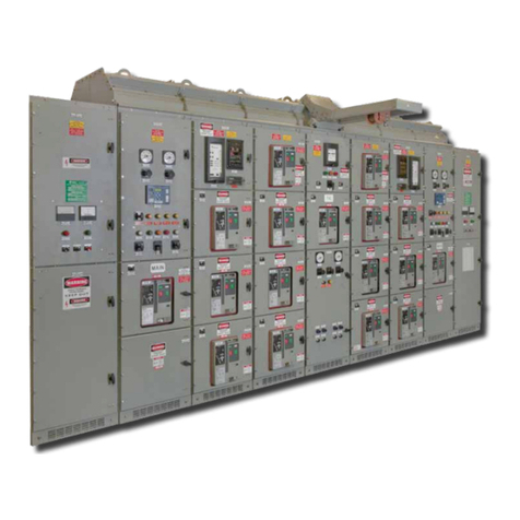
Powell PowlVac 63kA Training manual

Powered by Safety®
IB-26100 PowlVac® 63kA Enclosed Indoor
Disconnect Switch
Model: 15.0kV, 63kA 5000A
August, 2005

Powered by Safety®
2
Enclosed Indoor Disconnect Switch IB-26100
Powell Electrical Systems, Inc.
www.powellind.com
Powell Apparatus Service
E-mail: Info@powellservice.com
PO Box 12818, Houston, Texas 77217-2818
Tel: 713-944-6900
Fax: 713-947-4453
Contact Information

Powered by Safety®i
IB-26100Enclosed Indoor Disconnect Switch
Contents
I. INTRODUCTION ..........................................................................................................................2
A. SCOPE ...................................................................................................................................2
B. PURPOSE ..............................................................................................................................2
C. INSTRUCTION BULLETINS AVAILABLE ON THE INTERNET .............................................2
II. SAFETY .......................................................................................................................................3
A. SAFE WORK CONDITION .....................................................................................................3
B. SAFETY RULES .....................................................................................................................3
1) General ............................................................................................................................3
C. SAFETY LABELS ...................................................................................................................4
III. DESCRIPTION .............................................................................................................................5
A. DISCONNECTING SWITCHES ..............................................................................................5
1) General ............................................................................................................................5
2) Construction and Operation ............................................................................................5
3) Accessories .....................................................................................................................6
a) Grounding (Earthing) Contacts ........................................................................................6
b) Auxiliary Switch ...............................................................................................................7
c) Key Interlocks ..................................................................................................................7
B. OPERATING MECHANISM DESCRIPTION ........................................................................10
1) General ..........................................................................................................................10
2) Mechanism Operation ................................................................................................... 10
IV. INSTALLATION ......................................................................................................................... 13
A. RECEIVING .......................................................................................................................... 13
B. INSTALLING THE DISCONNECTING SWITCH ................................................................... 13
C. HANDLING ...........................................................................................................................13
D. STORAGE ............................................................................................................................ 13
V. MAINTENANCE .........................................................................................................................15
A. GENERAL ............................................................................................................................ 15
B. INSPECTION AND CLEANING ............................................................................................ 15
C. SETTINGS ............................................................................................................................ 15
D. LUBRICATION ......................................................................................................................16
E. HIGH VOLTAGE INSULATION INTEGRITY ........................................................................ 16
VII. RENEWAL PARTS .................................................................................................................... 17
A. ORDERING .......................................................................................................................... 17

Powered by Safety®
ii
Enclosed Indoor Disconnect Switch IB-26100
Figures
Tables
Table A. Ratings .....................................................................................................................................5
Table B. Renewal Parts .......................................................................................................................18
Figure 1 General Arrangement of the PowlVac® Enclosed Indoor Disconnect Switch .................... 6
Figure 2. PowlVac® Enclosed Indoor Disconnect Switch .................................................................. 7
Figure 3. PowlVac® Enclosed Indoor Disconnect Switch Interior Dimensions ................................... 8
Figure 4. PowlVac® Enclosed Indoor Disconnect Switch Front Interior Dimensions .......................... 8
Figure 5. PowlVac® Enclosed Indoor Disconnect Switch Operating Mechanism
Dimensions - Left Side ........................................................................................................ 9
Figure 6. PowlVac® Enclosed Indoor Disconnect Switch Operating Mechanism
Dimensions - Right Side ...................................................................................................... 9
Figure 7. PowlVac® Enclosed Indoor Disconnect Switch Operating Mechanism Dimensions ..........11
Figure 8. PowlVac® Enclosed Indoor Disconnect Switch Operating Mechanism ..............................12
Figure 9. Pivot Contact Spring Setting ...............................................................................................15
Figure 10. Moving Contact Springs Setting .........................................................................................16

Powered by Safety®1
IB-26100Enclosed Indoor Disconnect Switch
BEFORE ANY ADJUSTMENT, SERVICING, PARTS REPLACEMENT,
OR ANY OTHER ACT IS PERFORMED REQUIRING PHYSICAL
CONTACT WITH THE ELECTRICAL WORKING COMPONENTS OR
WIRING OF THE EQUIPMENT DESCRIBED IN THIS DOCUMENT, THE
POWER SUPPLY MUST BE DISCONNECTED. FAILURE TO FOLLOW
THIS WARNING MAY RESULT IN INJURY OR DEATH.
WARNING
!
THE EQUIPMENT DESCRIBED IN THIS DOCUMENT MAY CONTAIN
HIGH VOLTAGES AND CURRENTS WHICH CAN CAUSE SERIOUS
INJURY OR DEATH.
THE EQUIPMENT IS DESIGNED FOR USE, INSTALLATION,
AND MAINTENANCE BY KNOWLEDGEABLE USERS OF SUCH
EQUIPMENT HAVING EXPERIENCE AND TRAINING IN THE FIELD
OF HIGH VOLTAGE ELECTRICITY. THIS DOCUMENT, AND ALL
OTHER DOCUMENTATION SHALL BE FULLY READ, UNDERSTOOD,
AND ALL WARNINGS AND CAUTIONS SHALL BE ABIDED BY.
IF THERE ARE ANY DISCREPANCIES OR QUESTIONS, THE
USER SHALL CONTACT POWELL ELECTRICAL SYSTEMS, INC.
IMMEDIATELY AT 1-800-480-7273.
WARNING
!

Powered by Safety®
2
Enclosed Indoor Disconnect Switch IB-26100
THE INFORMATION IN THIS INSTRUCTION BULLETIN IS NOT INTENDED TO EXPLAIN ALL
DETAILS OR VARIATIONS OF ENCLOSED INDOOR DISCONNECT SWITCHES NOR TO
PROVIDE FOR EVERY POSSIBLE CONTINGENCY OR HAZARD TO BE MET IN CONNECTION
WITH INSTALLATION, TESTING, OPERATION, AND MAINTENANCE OF THE EQUIPMENT.
FOR ADDITIONAL INFORMATION AND INSTRUCTIONS FOR PARTICULAR PROBLEMS,
WHICH ARE NOT PRESENTED SUFFICIENTLY FOR THE USER’S PURPOSES, CONTACT
POWELL ELECTRICAL SYSTEMS, INC. AT 1-800-480-7273.
IMPORTANT
!
I. INTRODUCTION
A. SCOPE
This instruction bulletin describes the following:
PowlVac® 63kA Enclosed Indoor
Disconnect Switch
B. PURPOSE
The content of this document is intended to
provide the information and procedures required to
properly operate and maintain the enclosed indoor
disconnect switch in Section A.
This instruction bulletin contains the following
topics:
Description of the enclosed indoor
disconnect switch
Guidelines for safety
General descriptions of the operation
and maintenance of the enclosed indoor
disconnect switch
Instructions for installation and preparation
for use of the enclosed indoor disconnect
switch assemblies
Accessories
Renewal Parts
•
•
•
•
•
•
The illustrations contained in this document are
provided as general information to aid in showing
component locations. Therefore, the illustrations
may not represent the exact construction details
of the enclosed indoor disconnect switch. To the
extent required, the products described herein
meet the applicable ANSI, IEEE, and NEMA
standards; however, no such assurance is given
with respect to local codes and ordinances which
vary greatly.
C. INSTRUCTION BULLETINS AVAILABLE ON
THE INTERNET
Instruction bulletins are available through
hyperlinks on the Web site: www.powellind.com.
Click the following links: Publications, Services,
and Instruction Bulletins.
To obtain instruction bulletins by phone or email,
contact the Powell Apparatus Service (PAS) at 1-
800-480-7273 or 713-944-6900, or email PAS at
info@powellservice.com.
◄ SECTION END ►

Powered by Safety®3
IB-26100Enclosed Indoor Disconnect Switch
II. SAFETY
A. SAFE WORK CONDITION
The information in Section A is quoted from NFPE
70E 2004 —Article 120 Page 120.1
Establishing an Electrically Safe Work Condition
120.1 Process of Achieving an Electrically Safe
Work Condition.
Determine all possible sources of electrical
supply to the specific equipment. Check
applicable up-to-date drawings, diagrams, and
identification tags.
After properly interrupting the load current,
OPEN the disconnecting device(s) for each
source.
Wherever possible, visually verify that all
blades of the disconnecting devices are fully
open or that drawout type circuit breakers are
withdrawn to the fully disconnected position.
Apply lockout/tagout devices in accordance
with a documented and established policy.
Use an adequately rated voltage detector to
test each phase conductor or circuit part to
verify they are deenergized. Test each phase
conductor or circuit part both phase-to-phase,
and phase-to-ground. Before and after each
test, determine that the voltage detector is
operating satisfactorily.
Where the possibility of induced voltages
or stored electrical energy exists, ground
the phase conductors or circuit parts before
touching them. Where it could be reasonably
anticipated that the conductors or circuit
parts being deenergized could contact other
exposed energized conductors or circuit parts,
apply ground connecting devices rated for the
available fault duty.
1.
2.
3.
4.
5.
6.
B. SAFETY RULES
Study this instruction bulletin and all other
associated documentation before uncrating
the PowlVac® 63kA 5000A Enclosed Indoor
Disconnect Switch.
Each user has the responsibility to instruct and
supervise all personnel associated with usage,
installation, operation, and maintenance of this
equipment on all safety procedures which must
be observed. Furthermore, each user has the
responsibility of devising a complete safety
program for each type of equipment encountered.
The enclosed indoor disconnect switch described
in this instruction bulletin is operated by high
energy mechanisms interlocked to provide specific
operating sequences. To ensure the safety of
personnel associated with usage, installation,
operation, and maintenance of this enclosed
indoor disconnect switch, it is mandatory that
the following safety rules be observed. THESE
RULES ARE NOT INTENDED TO BE A
COMPLETE SAFETY PROGRAM, BUT ARE
INTENDED TO COVER ONLY THE IMPORTANT
ASPECTS OF PERSONNEL SAFETY RELATED
TO POWLVAC® 63KA 5000A ENCLOSED
INDOOR DISCONNECT SWITCH.
1) General
Only supervised and qualified personnel
trained in the usage, installation, operation,
and maintenance of the enclosed indoor
disconnect switch shall be allowed to work
on this equipment. It is mandatory that this
instruction bulletin, any supplements, and
service advisories be studied, understood, and
followed.
Maintenance programs must be consistent with
both customer experience and manufacturer’s
recommendations, including service advisories
and the instruction bulletin(s). A well-planned
and executed routine maintenance program
is essential for enclosed indoor disconnect
switch reliability and safety.
1.
2.

Powered by Safety®
4
Enclosed Indoor Disconnect Switch IB-26100
Service conditions and enclosed indoor
disconnect switch applications shall also
be considered in the development of such
programs, including such variables as ambient
temperature and humidity, actual continuous
current, thermal cycling, number of operations,
and any unusual local conditions such as
excessive dust, ash, corrosive atmosphere,
vermin, and insect problems.
3. C. SAFETY LABELS
The switch has DANGER, WARNING, CAUTION,
and instruction labels attached to various
locations. All equipment DANGER, WARNING,
CAUTION, and instruction labels shall be
observed.
◄ SECTION END ►

Powered by Safety®5
IB-26100Enclosed Indoor Disconnect Switch
III. DESCRIPTION
A. DISCONNECTING SWITCHES
1) General
The Powell enclosed indoor disconnect switch
is a 3-pole, motor-operated, knife-type “non-
load” switch. This disconnect switch does not
have current breaking and making capabilities.
This disconnect switch meets requirements
for short-time current and momentary (peak)
withstand current. This disconnect switch has
continuous (normal) current rating. See Table A
for disconnect switch ratings.
Table A. Ratings
Category Rating
Maximum Voltage 15.0kV
Lightning Impulse Withstand
Voltage
95.0kV
Power Frequency withstand
Voltage
36.0kV
Power Frequency 60 Hz
Continuous Current 5000A
Momentary Withstand Current 172.6kA Peak
Short-Time Withstand Current 63kA
Short-Time Current Withstand
Duration
3 s
THE POWELL DISCONNECT SWITCH
SHALL BE INTERLOCKED OR
OTHERWISE PREVENTED FROM
OPENING WHEN ANY AMOUNT OF
LOAD CURRENT IS FLOWING. THE
SWITCH SHALL ONLY BE OPERATED
WHEN NO VOLTAGE CHANGE OCCURS
ACROSS THE TERMINALS OF EACH
OF THE SWITCH POLES. DUE TO THE
WIDE VARIETY OF APPLICATIONS
AND INTERLOCKING SCHEMES, THE
INTERLOCKS OR OTHER METHODS OF
PREVENTING IMPROPER DISCONNECT
SWITCH OPERATION ARE NOT
SUPPLIED WITH THE BASIC SWITCH
AND SHALL BE THE RESPONSIBILITY
OF THE USER. FAILURE TO FOLLOW
THIS WARNING WILL RESULT IN
SEVERE EQUIPMENT DAMAGE AND
MAY CAUSE INJURY OR DEATH.
WARNING
!
2) Construction and Operation
Refer to Figures 1 through 6 for illustrations of
the physical description of the enclosed indoor
disconnect switch. To review detailed drawing of
the switch operating mechanism, refer to Figure 7
and Figure 8.
The base of the disconnect switch is constructed
of welded steel plate for rigidity. The base is
finished with an ANSI 61 gray powder-coating
process for long-term corrosion protection. The
primary phase-to-ground insulation is NEMA
grade GPO-3 polyester fiberglass.
The primary contacts for this disconnect switch
are made of hard drawn, high-conductivity copper.
Parallel flat copper bars are used for the moving
contacts. Heavy silver plating of the stationary
and moving contacts guards against wear. The

Powered by Safety®
6
Enclosed Indoor Disconnect Switch IB-26100
Figure 1. General Arrangement of the PowlVac® Enclosed Indoor Disconnect Switch
required contact force is achieved by multiple disc
springs acting to compress the moving contacts
together. A welded main operating shaft in the
base of the 3-pole switch drives the moving
contacts through levers and insulated operating
links. The main shaft is common to all three poles
ensuring synchronized operation of the poles.
3) Accessories
Powell enclosed indoor disconnect switches are
available with following options and accessories:
OPEN Position Grounding Contacts for
the Moving Contacts
Auxiliary Switches
Key Interlocks
•
•
•
a) Grounding (Earthing) Contacts
Grounding contacts can be installed on the
disconnect switch for grounding the moving
contacts in the OPEN position (Figure 8).
Grounding contacts and the supporting ground
bus can be mounted to the switchgear in such
a way that the stationary grounding contacts
engage the moving contacts of the disconnect
switch towards the end of the opening stroke. The
grounding contacts are made from hard-drawn,
high-conductivity copper.
When the disconnect switch is opened, the
moving contacts of the disconnect switch rotate
and connect with the grounding contacts. With
this design, there is no need for any additional
interlocks to prevent grounding the incoming
primary connections when the disconnect switch
is CLOSED.

Powered by Safety®7
IB-26100Enclosed Indoor Disconnect Switch
Figure 2. PowlVac® Enclosed Indoor Disconnect Switch
b) Auxiliary Switch
Optional auxiliary switches can be mounted to
the wall of the enclosure or to the frame of the
enclosed indoor disconnect switch. The optional
auxiliary switches are provided with single pole
double throw contacts.
c) Key Interlocks
Key interlocks can be provided to ensure proper
operating sequences of the disconnect switch.
The disconnect switch operating mechanism has
provisions for mounting key interlocks in both the
OPEN and CLOSED positions of the switch.

Powered by Safety®
8
Enclosed Indoor Disconnect Switch IB-26100
Figure 3. PowlVac® Enclosed Indoor Disconnect Switch
Interior Dimensions
Figure 4. PowlVac® Enclosed Indoor Disconnect Switch
Front Interior Dimensions

Powered by Safety®9
IB-26100Enclosed Indoor Disconnect Switch
Figure 5. PowlVac® Enclosed Indoor Disconnect Switch
Operating Mechanism Dimensions - Left Side
Figure 6. PowlVac® Enclosed Indoor Disconnect Switch
Operating Mechanism Dimensions - Right Side

Powered by Safety®
10
Enclosed Indoor Disconnect Switch IB-26100
B. OPERATING MECHANISM DESCRIPTION
1) General
The main operating shaft of the disconnect
switch is motor-driven to the OPEN and CLOSED
positions through a right angle gear box. The
gearbox, which is bolted to the base of the switch,
contains worm and wheel type gearing and
connects the gear motor to the main operating
shaft. The inherent anti-reversing nature of worm
and wheel gearing ensures the moving contacts
of the disconnect switch will not change positions
or move unless the input shaft to the gearbox is
rotated.
The drive motor is located in a low-voltage
compartment of the enclosure for ease of
operation and maintenance. The output of the
drive motor is connected to the input of the
gearbox through a steel operating shaft. The
drive motor is a dual-output, common shaft
construction. A hexagonal adapter is provided
on the output shaft opposite the shaft that is
connected to the gearbox. The adapter makes it
possible to manually override the motor to operate
the switch when control power is not available.
The adapter can be covered with a lockable
protection cover to deter manual operation. The
motorized operating mechanism can be equipped
with electrical and mechanical interlocking.
2) Mechanism Operation
The following description of the mechanism
operation does not address the required
interlocking or operating procedures as required in
Section III. DESCRIPTION, A. DISCONNECTING
SWITCHES 1) General. This section is
provided to describe only the functional aspects
of the motor operated switch mechanism for
maintenance and troubleshooting purposes.
Refer to Figure 8 for component identification.
When the gear motor (Figure 8, a) is
energized, rotational force is transmitted to
the right angle gear box (Figure 8, j) via the
gearbox input shaft (Figure 8, l). The gearbox
1.
input shaft is connected to the gearbox by a
cylindrical shaft coupler (Figure 8, c). The
opposite end of the input shaft is connected to
a torque-limiting device by a shaft coupler.
The torque limiting device is a preset
ratcheting design used to prevent excessive
torque from being applied to the gearbox. The
output of the gear motor is connected to the
torque limiter by a shaft coupler.
The output of the right angle gearbox (Figure
8, l) is connected to the main operating
shaft (Figure 8, k) of the disconnect switch.
Rotating the input shaft of the gearbox causes
a proportional rotation of the main operating
shaft. Full operation of the disconnect switch
is accomplished by rotating the main operating
shaft 45 to 50 degrees. Excessive rotation
is prevented by the limit switches mounted to
define the OPEN and CLOSED position of the
disconnect switch.
The operating mechanism support brackets
(Figure 8, e) and support angle (Figure 8, f)
support the gear motor and gearbox input
shaft. A portion of the gearbox input shaft is
externally threaded and is equipped with an
internally threaded slider. The slider (Figure
8, g) moves horizontally in proportion to the
rotation of the input shaft.
The slider (Figure 8, g) is designed to perform
three functions. The slider operates limit
switches that control motor operation and
switch main contact position, mechanically
drives the OPEN-CLOSED indicator flag and
also drives the mechanical position interlocks.
2.
3.
4.

Powered by Safety®11
IB-26100Enclosed Indoor Disconnect Switch
Figure 7. PowlVac® Enclosed Indoor Disconnect Switch
Operating Mechanism Dimensions

Powered by Safety®
12
Enclosed Indoor Disconnect Switch IB-26100
a. Motor
b. Hex Rod End
c. Couplers (2)
d. Torque Limiter
e. Support Brackets
f. Support Angle
g. Slider
h. Ground Bus (Optional Open Position Grounding Contacts)
i. Threaded Rod
j. Gear Box (Right Angle)
k. Main Operator Shaft
l. Gear Box Input Shaft
a
b
f
c
d
e
g
i
c
j
k
h
l
Figure 8. PowlVac® Enclosed Indoor Disconnect Switch
Operating Mechanism
◄ SECTION END ►

Powered by Safety®13
IB-26100Enclosed Indoor Disconnect Switch
IV. INSTALLATION
A. RECEIVING
Upon receipt, remove any shipping material and
inspect the enclosed indoor disconnect switch for
damage that may have occurred during shipment.
Check equipment received against the shipping
documents to ensure receipt of the complete
shipment.
B. INSTALLING THE DISCONNECTING
SWITCH
The switch is designed for metal-enclosed indoor
applications. Refer to the installation drawings
supplied with the switch for mounting bolt
locations, electrical clearances and ventilation
requirements. Refer to Figures 3 through 6 a
typical switch outline with dimensions.
The enclosed indoor disconnect switch must
be firmly attached to a square and level base.
Care should be taken during installation to and
tightening of the mounting hardware to avoid
twisting the frame.
Care should also be taken when installing
primary copper connections to the switch
terminals. Unnecessarily high torques or static
loads on the terminals due to improper conductor
installation must be avoided as these may cause
misalignment and binding of the switch contacts.
In order to maintain short-circuit withstand ratings
of the switch; the distance to the nearest support
insulator from the switch terminals must not
exceed 36 inches.
C. HANDLING
The enclosed indoor disconnect switch weighs
approximately 850 lbs. The preferred method for
moving the enclosed indoor disconnect switch is
by overhead crane.
THE SWITCH MUST BE LIFTED BY
ATTACHING LIFTING MEANS TO THE
BASE OF SWITCH ONLY. LIFTING THE
SWITCH BY USING ANY OF THE HIGH-
VOLTAGE COPPER CONDUCTORS WILL
RESULT IN DAMAGE TO THE SWITCH!
CAUTION
!
D. STORAGE
IT IS RECOMMENDED THAT THE
INDOOR DISCONNECTING SWITCH BE
PLACED INTO SERVICE IMMEDIATELY
IN ITS PERMANENT LOCATION AFTER
COMPLETING THE COMMISSIONING
TESTS. IF THIS IS NOT POSSIBLE,
THE FOLLOWING PRECAUTIONS
MUST BE TAKEN TO ENSURE THE
PROPER STORAGE OF THE INDOOR
DISCONNECTING SWITCH
CAUTION
!
Since moisture has an adverse effect on
the insulating parts, the enclosed indoor
disconnect switch should be carefully
protected against condensation, preferably
by storing it in a warm dry room of moderate
temperature, such as 40°-100°F. Enclosed
indoor disconnect switches used in outdoor
metal-clad switchgear should be stored in the
equipment only when power is available and
the anti-condensation heaters are in operation.
1.

Powered by Safety®
14
Enclosed Indoor Disconnect Switch IB-26100
The enclosed indoor disconnect switch
should be stored in a clean location free from
corrosive gases or fumes. Particular care
should be taken to protect the equipment from
moisture and cement dust, as this combination
has a corrosive effect on many parts.
Unplated surfaces, such as, rollers, latches,
etc., should be coated with grease/oil to
prevent rusting.
2.
3.
If the enclosed indoor disconnect switch is stored
for any length of time, it should be inspected
periodically to see that rusting has not started and
to ensure good mechanical condition. Should
the enclosed indoor disconnect switch be stored
under unfavorable atmospheric conditions, it
should be cleaned and dried before attempting
the commissioning tests and before placing the
enclosed indoor disconnect switch into service.
◄ SECTION END ►

Powered by Safety®15
IB-26100Enclosed Indoor Disconnect Switch
V. MAINTENANCE
A. GENERAL
A regular maintenance schedule should be
established to obtain the best service and
reliability from the enclosed indoor disconnect
switch. Actual inspection and maintenance will
depend on individual application conditions such
as number of operations, desired system reliability
and storage conditions. Some atmospheric
conditions such as extremes of dust, moisture,
or corrosive gases might indicate inspection and
maintenance at more frequent intervals. Very
clean and dry conditions will justify longer times
between inspection and maintenance operations.
With experience, each user can set an inspection
and maintenance schedule which is best suited for
the particular use.
When the enclosed indoor disconnect switch has
been in storage for an extended period of time, it
must be inspected and cleaned before being used.
See Section IV. INSTALLATION, C. STORAGE.
A permanent record of maintenance work and
inspections should be kept. The degree of record
detail depends on the operating conditions.
Dates and results of inspections and routine
maintenance activities should be recorded starting
from the date the switch is first put into service.
B. INSPECTION AND CLEANING
Inspect the enclosed indoor disconnect switch for
loose or damaged hardware or parts. Tighten any
loose hardware, and replace missing or damaged
hardware or parts.
When necessary, remove loose dust and dirt
from the enclosed indoor disconnect switch
with a vacuum cleaner, a clean, dry cloth, or an
industrial type wiper. DO NOT use an air hose to
clean the enclosed indoor disconnect switch. Dirt
or grit may be blown into critical parts, including
bearings, which will cause excessive wear of the
parts.
Primary insulation, including the main contact
supports and the insulating operating links, should
also be cleaned. Wipe clean with a dry lint-free
cloth or an industrial type wiper. If dirt adheres
and will not come off by wiping, remove it with
denatured alcohol. Be sure that the switch is dry
before returning it to service. Do not use any type
of detergent to wash the surface of the insulators
as detergent may leave an electrical conducting
residue on the surface as it dries.
WHEN CLEANING THE
DISCONNECTING SWITCH, USE ONLY
DENATURED ALCOHOL OR ISOPROPYL
ALCOHOL TO REMOVE FOREIGN
MATERIAL. FAILURE TO DO SO MAY
DAMAGE THE DIELECTRIC AND/OR
THE MECHANICAL PROPERTIES OF
THE INSULATION.
CAUTION
!
C. SETTINGS
During maintenance, check the contact spring
settings. The correct setting for the pivot contact
springs is shown in Figure 9.
Figure 9. Pivot Contact Spring Setting
0.14 / 0.16
0.14 / 0.16

Powered by Safety®
16
Enclosed Indoor Disconnect Switch IB-26100
The moving contact springs setting is as shown in
Figure 10.
Figure 10. Moving Contact Springs Setting
D. LUBRICATION
Lubrication of switch moving parts should be
performed at the regular maintenance intervals.
The guiding rule in lubrication should be to
lubricate regularly, use lubricant sparingly, and
remove all excess lubricant.
The lubricant on the main contacts of the
disconnect switch should be renewed
approximately every 2 years. Use only Mobil
Grease 28 for lubricating the main contacts.
Substituting other greases or lubricants on the
contacts may cause overheating, binding or
welding of the contacts.
Lubrication requirements of the operating
mechanism are minimal. The motor and right
angle gearbox are lubricated at the factory and
should not require replenishment during the life
of the components. Rheolube-368A should be
used to lubricate moving parts of the operating
mechanism.
Powell offers a complete lubrication kit (Powlube-
102) which contains all the lubricants required for
maintaining the switch.
E. HIGH VOLTAGE INSULATION INTEGRITY
The high voltage insulation system of the
disconnect switch, which consists of the insulated
operating links and contact support assemblies,
should be hipot tested prior to initially placing the
switch in service. The switch primary phase-to-
phase and phase-to-ground insulation should be
tested with the switch in the CLOSED position.
Test each pole of the switch separately, with
the other two poles and the switch base (frame)
grounded.
Field primary insulation integrity testing can be
conducted with either AC or DC high potential
testing (Hipot). Powell recognizes that DC testing
is very common due to the availability of the
equipment. When using DC voltages, consistent
and historical readings are more important than
predetermined values when determining the
condition of the primary insulation system. A
clean, dry switch will help yield accurate and
consistent readings.
The recommended maintenance test voltage for
the disconnect switch is:
27 kVAC for one minute,
or
37kVDC for one minute.
◄ SECTION END ►
•
•
Table of contents
Other Powell Switch manuals