manuals.online logo
Brands
  1. Home
  2. •
  3. Brands
  4. •
  5. THOMSON
  6. •
  7. LCD TV
  8. •
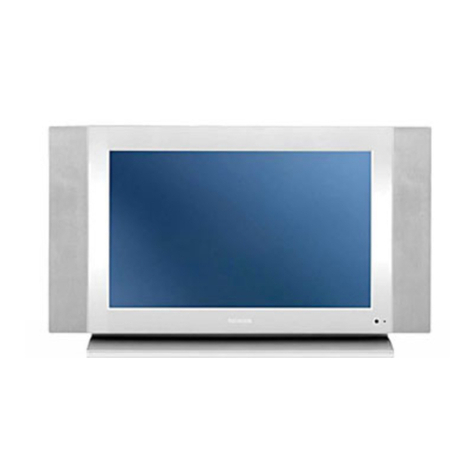
  9. THOMSON LCD12B2 User manual

THOMSON LCD12B2 User manual

This manual suits for next models

4

Other THOMSON LCD TV manuals

THOMSON 30L03B User manual

THOMSON

THOMSON 30L03B User manual

THOMSON 27LCDB03B User manual

THOMSON

THOMSON 27LCDB03B User manual

THOMSON 32LB030B5 User manual

THOMSON

THOMSON 32LB030B5 User manual

THOMSON LCD TV User manual

THOMSON

THOMSON LCD TV User manual

THOMSON 22E92NH22 User manual

THOMSON

THOMSON 22E92NH22 User manual

THOMSON IFC228 User manual

THOMSON

THOMSON IFC228 User manual

THOMSON LCD12B User manual

THOMSON

THOMSON LCD12B User manual

THOMSON 27LM051B6 User manual

THOMSON

THOMSON 27LM051B6 User manual

THOMSON EFC031 User manual

THOMSON

THOMSON EFC031 User manual

THOMSON L4218HD User manual

THOMSON

THOMSON L4218HD User manual

THOMSON LB030 User manual

THOMSON

THOMSON LB030 User manual

THOMSON 27LB125 User manual

THOMSON

THOMSON 27LB125 User manual

THOMSON 32FS6646 Installation guide

THOMSON

THOMSON 32FS6646 Installation guide

THOMSON LCD03B User manual

THOMSON

THOMSON LCD03B User manual

THOMSON EFC030 User manual

THOMSON

THOMSON EFC030 User manual

THOMSON SCENIUM 42LB330B5 User manual

THOMSON

THOMSON SCENIUM 42LB330B5 User manual

THOMSON 27LB120S4 - annexe 1 User manual

THOMSON

THOMSON 27LB120S4 - annexe 1 User manual

THOMSON AV1 User manual

THOMSON

THOMSON AV1 User manual

THOMSON 20LW052 User manual

THOMSON

THOMSON 20LW052 User manual

THOMSON DVD Player + TV Set + VCR User manual

THOMSON

THOMSON DVD Player + TV Set + VCR User manual

THOMSON 32LM051B6 User manual

THOMSON

THOMSON 32LM051B6 User manual

THOMSON L40M71A2 User manual

THOMSON

THOMSON L40M71A2 User manual

THOMSON 32LB115B5 User manual

THOMSON

THOMSON 32LB115B5 User manual

THOMSON 32LB115 User manual

THOMSON

THOMSON 32LB115 User manual

Popular LCD TV manuals by other brands

Samsung LA32E420 E-manual

Samsung

Samsung LA32E420 E-manual

ViewSonic VS12119-1M user guide

ViewSonic

ViewSonic VS12119-1M user guide

iLO CIWL3706 owner's manual

iLO

iLO CIWL3706 owner's manual

LG 32LT560C Quick reference guide

LG

LG 32LT560C Quick reference guide

Sony WEGA KLV-27HR3 operating instructions

Sony

Sony WEGA KLV-27HR3 operating instructions

Zenith Z32LC2D Specifications

Zenith

Zenith Z32LC2D Specifications

Sony KDL-32S3000R - 32" Class Bravia S-series Digital Lcd... Specifications

Sony

Sony KDL-32S3000R - 32" Class Bravia S-series Digital Lcd... Specifications

Medion MEDION LIFE X14330 quick start guide

Medion

Medion MEDION LIFE X14330 quick start guide

Vizio HDTV30A VW32L Service manual

Vizio

Vizio HDTV30A VW32L Service manual

Sharp LC-24DV250K Operation manual

Sharp

Sharp LC-24DV250K Operation manual

SOYO Dymond DYLT032A user manual

SOYO

SOYO Dymond DYLT032A user manual

Kalley K-LED40FHDST2 Service manual

Kalley

Kalley K-LED40FHDST2 Service manual

Dynex DX-L40-10A Guide de l'utilisateur

Dynex

Dynex DX-L40-10A Guide de l'utilisateur

Hisense M3300 user manual

Hisense

Hisense M3300 user manual

Toshiba 42XV600A owner's manual

Toshiba

Toshiba 42XV600A owner's manual

Panasonic TX-26LX1A operating instructions

Panasonic

Panasonic TX-26LX1A operating instructions

HP LT3200 Illustrated parts & service map

HP

HP LT3200 Illustrated parts & service map

Sharp LC-32GA8 Service manual

Sharp

Sharp LC-32GA8 Service manual

manuals.online logo
manuals.online logoBrands
  • About & Mission
  • Contact us
  • Privacy Policy
  • Terms and Conditions

Copyright 2025 Manuals.Online. All Rights Reserved.

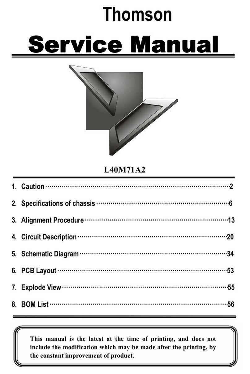
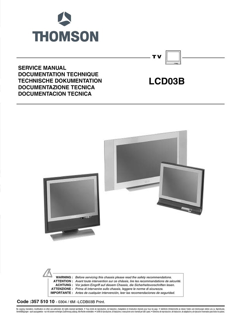
SERVICE MANUAL
DOCUMENTATION TECHNIQUE
TECHNISCHE DOKUMENTATION
DOCUMENTAZIONE TECNICA
DOCUMENTACION TECNICA
No copying, translation, modification on other use authorized. All rights reserved worldwide. • Tous droits de reproduction, de traduction, d'adaptation et d'exécution réservés pour tous les pays. • Sämtliche Urheberrechte an diesen Texten und Zeichnungen stehen uns zu. Nachdrucke,
Vervielfältigungen - auch auszugsweise - nur mit unserer vorherigen Zustimmung zulässig. Alle Rechte vorbehalten.• I diritti di riproduzione, di traduzione, e esecuzione sono riservati per tutti i paesi. • Derechos de reproduccion, de traduccion, de adaptacion y de ejecucion reservados para todos los paises.
WARNING : Before servicing this chassis please read the safety recommendations.
ATTENTION : Avant toute intervention sur ce châssis, lire les recommandations de sécurité.
ACHTUNG : Vor jedem Eingriff auf diesem Chassis, die Sicherheitsvorschriften lesen.
ATTENZIONE : Prima di intervenire sullo chassis, leggere le norme di sicurezza.
IMPORTANTE : Antes de cualquier intervención, leer las recomendaciones de seguridad.
Code : 358 597 20 - 0305 / 6M - LCD12B - 27”, 30”, 32” Print.
LCD12B
27”, 30”, 32”
TV
Indicates critical safety components, and identical components should be used for replacement. Only then can the
operational safety be garanteed.
Le remplacement des éléments de sécurité (repérés avec le symbole ) par des composants non homologués selon la
Norme CEI 65 entraine la non-conformité de l'appareil. Dans ce cas, la responsabilité du fabricant n'est plus engagée.
Wenn Sicherheitsteile (mit dem Symbol gekennzeichnet) nicht durch Original - Ersatzteile ersetzt werden, erlischt die
Haftung des Herstellers.
La sostituzione dei componenti di sicurezza (evidenziati con il segno ) con componenti non omologati secondo la
norma CEI 65 comporta la non conformitá dell'apparecchio. In tal caso è "esclusa la responsabilità " del costruttore.
La sustitución de elementos de seguridad (marcados con el simbolo ) por componentes no homologados segun la
norma CEI 65, provoca la no conformidad del aparato. En ese caso, el fabricante cesa de ser responsable.
MEASUREMENT CONDITIONS - CONDITIONS DE MESURES - MESSBEDINGUNGEN
CONDIZIONI DI MISURA - CONDICIONES DE MEDIDAS
RICEVITORE :
In UHF, livello d'entrata 1 mV, monoscopio barre :
- PAL, norma G. bianco 100%.
Via SCART, livello d'entrata 1 Vpp, monoscopio barre :
Colore, Contrasto, Luminositá media, Suono minimo.
Programma selezionato PR 01.
Tensioni continue rilevate rispetto alla massa con un voltmetro digitale.
RECEIVER :
On UHF,input level : 1 mV, bar test pattern :
- PAL, I standard, 100% white.
Via the scart socket, input level : 1 Vpp, bar test pattern :
Colour, contrast and brightness at mid-position, sound at minimum.
Programme selected : PR 01.
DC voltages measured between the point and earth using a digital
voltmeter.
EMPFÄNGER :
Bei UHF Eingangspegel 1 mV, Farbbalken :
- PAL, Norm G, Weiss 100%.
Über die Scartbuchse : Eingangspegel 1 Vss, Farbbalken :
Farbe, Kontrast, Helligkeit in der Mitte des Bereichs, Ton auf Minimum.
Zugeordnetes Programm PR 01.
Gleichspannungen mit einem digitalen Voltmeter zur Masse gemessen.
RECEPTEUR :
En UHF, niveau d'entrée 1 mV mire de barres
- SECAM, Norm L, Blanc 100%.
Par la prise Péritélévision, niveau d'entrée 1 Vcc, mire de barres .
Couleur, contraste, lumière à mi-course, son minimum.
Programme affecté PR 01.
Tensions continues relevées par rapport à la masse avec un
voltmètre numérique.
RECEPTOR :
En UHF, nivel de entrada 1 mV, mira de barras :
- PAL, norma G, blanco 100%.
Por la toma Peritelevision, nivel de entrada 1 Vpp mira de barra.
Color, Contraste, luz a mitad de carrera, Sonido minimo.
Programa afectado PR 01.
Tensiones continuas marcadas en relacion a la masa con un voltimetro digital.
MAIN
FRANÇAIS ESPAÑOLDEUTSCHENGLISH ITALIANO
1
2
3
4
5
6
7
8
9
10
11
12
13
14
15
16
17
18
19
20
21
NC
21
17
19
15
13
20
18
16
14
12
11
910
8
7
5
3
1
6
4
2
NC
AUDIO "R"
AUDIO "R"
AUDIO "L"
NOTE :
... etc. identifies each
pcb module.
AUDIO "D"
AUDIO "D"
AUDIO "G"
AUDIO
"BLEU"
AUDIO "G" MONO
"BLEU"
COMMUT. LENTE
"VERT"
"VERT"
"ROUGE"
COMMUT. RAPIDE
COMMUT. RAPIDE
VIDEO
VIDEO SYNCHRO
BLINDAGE PRISE
AUDIO "R"
AUDIO "R"
AUDIO "L"
AUDIO
"BLAU"
AUDIO "L" MONO
"BLAU"
AV
UMSCHALTUNG
"GRÜN"
"GRÜN"
"ROT"
AUSTASTUNG
AUSTASTUNG
VIDEO
VIDEO ODER
SYNCHRO
ABSCHIRMUNG
DES STECKERS
AUDIO "D"
AUDIO "D"
AUDIO "I"
AUDIO
"AZUL"
AUDIO "I" MONO
AZUL
"CONMUTACION
LENTA"
"VERDE"
"VERDE"
"ROJA"
"CONMUTACION
RAPIDA"
"CONMUTACION
RAPIDA"
VIDEO
VIDEO O SINCRO
BLINDAJE
DEL ENCHUFE
AUDIO "D"
AUDIO "D"
AUDIO "S"
AUDIO
"BLU"
AUDIO "S" MONO
BLU
"COMMUTAZIONE
LENTA"
"VERDE"
"VERDE"
"ROSSO"
"COMMUTAZIONE
RAPIDA"
"COMMUTAZIONE
RAPIDA"
VIDEO
VIDEO O SINCRO
INVOLUCRO METAL-
LICO DELLA PRESA
AUDIO "L" MONO
"BLUE"
"GREEN"
AV LINK AV LINK AV LINK AV LINK AV LINK
"GREEN"
"RED"
"ROUGE" "ROT" "ROJA""ROSSO""RED"
SLOW SWITCH
FAST SWITCH
VIDEO
VIDEO VIDEO VIDEOVIDEOVIDEO
PLUG SCREEN
BOX
VIDEO OR "SYNC"
FAST SWITCH
AUDIO
"BLUE"
: OUTPUT - SORTIE - AUSGANG - USCITA - SALIDA • : EARTH - MASSE - MASSE - MASSA - MASA
MAIN
NOTE :
... etc. repères des
platines constituant l'appareil.
MAIN
NOTA :
... etc. marcas de las
placas que constituyen el
aparato.
MAIN
NOTA :
... ecc. sigla delle
piastre dell' apparecchio.
MAIN
HINWEIS :
... usw. Kennzeichnung
der Platinen, aus denen das
Gerät zusammengesetzt ist.
: INPUT - ENTRÉE - EINGANG - ENTRATA - ENTRADA •
Do not disconnect modules when they are energized!
Repairs on power supply section are to be carried out only with isolating transformer.
Ne pas retirer les modules lorsqu' ils sont sous tension. N'effectuer les travaux de maintenance sur la partie reliée
au secteur (Switch Mode) qu'au travers d'un transformateur d'isolement.
Module nicht bei eingeschaltetem Gerät entfernen!
Servicearbeiten am Netzteil nur unter Verwendung eines Regeltrenntrafos durchführen.
Non scollegare le piastre quando sono alimentate!
Per le riparazioni sulla sezione alimentatore, utilizzare un trasformatore isolatore.
No desconectar los módulos cuando están activados. Las reparaciones en la sección de alimentación de energía
deben ser ejecutadas solamente con un transformador de separación.
LCD12B
First issue 03 / 05 3
INFORMATION - INFORMATIONS - INFORMATIONEN
INFORMAZIONE - INFORMACIONES
Chassis group table
1 - The electronic chassis configuration (modules) and schematic diagram page numbers.
2 - The chassis configuration.
Le tableau ci-dessous regroupe :
1 - L’environnement électronique de chaque chassis (modules) et le numéro de page où il est décrit.
2 - La désignation des chassis
Die nachstehendeTabelle umfaßt:
1 - Die elektronischen Baugruppen (Module) der Chassis varianten und die Seiten auf der sie beschrieben werden
2 - Die Chassisbezeichnung
La tabella qui di seguito contiene:
1 - l’ambiente elettronico di ogni telaio (moduli) e il numero di pagina nella quale è descritto.
2 - La descrizione dei telai
El cuadro siguiente agrupa:
1 - El entorno electrónico de cada chasis (módulos) y el número de página donde está descrito.
2 - La designación de los chasis
EN
FR
DE
IT
ES
Reference Information Block Service FCB KDB Inverter DC/DC Audio Earphone Main Video
Diagram Mode - - Power
Supply -- Board Board
27LCD120S4 34to 6 7 to 12 13 to 14 - 15 to 20 - 21 to 22 - 23 to 44 45 to 58
30LCD120S4 34to 6 7 to 12 13 to 14 - 15 to 20 - 21 to 22 - 23 to 44 45 to 58
32LCD120S4 34to 6 7 to 12 13 to 14 - 15 to 20 - 21 to 22 - 23 to 44 45 to 58
Chassis LCD12B
LCD12B
4First issue 03 / 05
BLOCK DIAGRAM - SCHEMA SYNOPTIQUE - BLOCKSCHALTBILD
SCHEMA A BLOCCHI - ESQUEMA DE BLOQUES
Tuner
Module
Main Board
LCD Panel
(Invertert)
PFC/DC+DC Board
30 pin
30 pin
AC
Input
50 pin EFC
PC S-
Video
AFE
AD9883
DVI
Receiver
HDCP
Sil169
Scaller
PW166B
LVDS
THC63LVDM83A
Flash
Audio
Processor
MSP3412G
Video
Decoder
VPC3230D Video Mux.
CXA2161R
De-Interlace
PW1230
Teltext
SDA555XFL
Keypad/IR
Interface
Analog Mux.
BA7657F
DDC
UART
PhoneJack
Audio Input Y CbCr Component L/R
Audio input Composite
Video
L/R Audio
Input
SCART1 SCART2
Block Diagram
Tuner Scart
Board
20 Pin
Audio Board
DDC
10 pin 12 pin
10 pin 12 pin
5 pin 16 pin
4 pin
6 pin
6 pin 16 pin
5 pin
50 pin FFC
14 pin
Keypad Board
12 pin
10 pin
5 pin
5 pin
12 pin
10 pin
DVI-I
DVI
Audio
14 pin
LCD12B
First issue 03 / 05 5
BLOCK DIAGRAM - SCHEMA SYNOPTIQUE - BLOCKSCHALTBILD - SCHEMA A BLOCCHI
ESQUEMA DE BLOQUES
Y
Tuner
PC AD9883
DVI-D Sil169
S-Video VPC3230D
YUV422
SDA555X
FL
Pixelworks
PW166B THC6 3L
VDM83 A
Composite
Video
To Panel
SCART 1
LVDS
signal
CXA2161R
SCART 1
Video Output
SCART 2
Video Output
MM1234+
ADG779
BA7657F
SCART 2
Pr/
Cr
Pb/
Cb
Differetial Sigal RGB 888 RGB 888
Video Signal Flow
LCD12B
6 First issue 03 / 05
BLOCK DIAGRAM - SCHEMA SYNOPTIQUE - BLOCKSCHALTBILD - SCHEMA A BLOCCHI -
ESQUEMA DE BLOQUES
Tuner
CXA7002R
MSP3412G
PC Phone-Jack
Input
TDA2822D
TDA7490
EarPhone
Output
Composite
Audio L/R
Input
PhoneJack
L/R Output
SCART 2 Audi o L/R Output
SCART 1 Audi o L/R Output
Audio Signal Flow
DVI
AUDIO
Component Audio FROM TUNER AUDIO
74HC4053D
SCART 2
SCART 1
LCD12B
First issue 03 / 05 7
Service Mode Operation Manual
Model support: 15” 20” and 20” bi-sonic
Service Mode
1. Press the “menu” button, and then the screen display will
appear “Overview” OSD, below as Figure Overview OSD.
Then press the “info” button and ”1”,”0”and ”3” buttons
step by step to enter Service Mode. And Figure
Service mode will appear on the screen display.
Mode Service
1.Presser la touche “Menu” l’ecran de selection ci-dessus apparait
Presser la touche “Info”, la touche “1” puis les touches “0” et “3” pour
acceder au “Mode Service”
Anleitung Service Mode
Für Modelle: 15“, 20“ und 20“ bi-sonic
Service Mode
1. Drücken sie die „MENU“ – Taste. Es erscheint das „Übersicht“
–Menü (siehe Abbildung 1). Drücken sie dann nacheinander die Tasten
„INFO“, „1“, „0“, und „3“. Die erste Seite des Service-Modes wird
angezeigt (siehe Abbildung 2).
Manuale Procedura Service Mode
Modelli: 15” 20” e 20” bi-colonna
Service Mode
1. Premere il tasto “menu” per far visualizzare il menu “Sommario”,
vedi pagina OSD.
Poi premere sequenzialmente i tasti “info” , “1”, “0” e “3” per entrare in
Service mode. Il menu di Service mode verrà visualizzata sullo schermo.
Per cambiare pagina premere il tasto “Menu”.
Menu Sommario
Manual de operación del Modo Servicio
Para modelos de : 15”, 20” y 20” bi-columna
Modo Servicio
1. Pulsar la tecla “menú”, en la pantalla se mostrará
el menú “OVERVIEW (ÍNDICE)”, como se muestra en
la figura MENU OVERVIEW (ÍNDICE).
A continuación, pulsar las teclas “info”, ”1”, ”0” y ”3” una tras otra
para entrar en Modo Servicio y se mostrará
la primera página del Modo Servicio en la pantalla.
Overview
Preferences
Installation
Sound
Picture
Figure Overview OSD
SERVICE MODE - MODE SERVICE - SERVICE-MODE - MODO SERVICIO
EN
FR
DE
ES
IT
Color temp P-N P-C V-CV-NP-W
Red Drive - 123 -
- 123 -
- 123 -
- 123 -
- 123 -
- 123 -
-
-
-
-
-
-
+
+
+
+
+
+
Red Offset
Green Drive
Green Offset
Blue Drive
Blue Offset
Reset To Default
Calibration...
Auto Turn on on off
Tuner 1D
190247
Eu 20L0BI
Ver 09171I
➠
Color temp P-N P-C V-CV-NP-W
Red Drive - 123 -
- 123 -
- 123 -
- 123 -
- 123 -
- 123 -
-
-
-
-
-
-
+
+
+
+
+
+
Red Offset
Green Drive
Green Offset
Blue Drive
Blue Offset
Reset To Default
Calibration...
Auto Turn on on off
Tuner 1D
190247
Eu 20L0BI
Ver 09171I
- “Change“ value
- Réglage de la valeur
- Wert “änden“
- “Cambiare“ valore
- “Cambiar“ valor
NAVIGATION INSIDE THE SERVICE MODE - DEPLACEMENT DANS LE MODE SERVICE
SUCHE IN SERVICE MODE - OPZIONI NEL SERVICE MODE - BUSQUEDA EN MODO SERVICIO
➠
REMOTE CONTROL - TELECOMMANDE - FERNBEDIENUNG
TELECOMANDO - MANDO A DISTANCIA
Naviagation up Naviagation down
VALUE
VALUE
>
<
- Press "Menu" button
- Appuyer sur la touche "Menu"
- Taste "Menu"
- Premere " Menu"
- Pulse "Menu"
Changing page - Changement de page
Seitenwechsel - Cambiare Pagina - Cambio de página
Choosing a setting from the menu / setting e value
Choix d'un réglage dans un menu / Réglage d'une valeur
Wahl einer einstellung in einem menü / Einstellung eines wertes
Scegliere una Regolazione dal Menu / Selezione di un valore
Eleccion de un Ajuste en un menu / Ajuste de un valor
LCD12B
8 First issue 03 / 05
1. Color Temp: P-N means “Normal” on YpbPr, V-N means “Normal” on
Video mode. Each item decide different gamma curve.
2. Red drive, Green drive and blue drive means gamma RGB gain.
Control by scaler
3. Red offset, Green offset and blue offset means gamma RGB offset.
Control by scaler
4. Reset To Default: press OK will load all default value on User OSD
5. Calibration: press this botton guide to calibrate A/D converter white
and black level on PC input. Also guide to calibrate A/D converter PbPr
offset on YpbPr input.
6. MV enable: (30") designer debug tool revision
( this is information only )
1. Color Temp: Temperature des couleurs.
P-N correspond à un reglage “Normal” /YpPr
V-N correspond à un reglage “normal” / mode vidéo
chaque item permet de règler la courbe de gamma.
2. Red drive, Green drive and blue drive: green drive et Bleu drive
correspond aux reglages de gain
du gamma RVB ( controlé par le scaler).
3. Red offset,green offset et blue offset: correspond aux réglage
d’offset du gamma RVB ( controlé par le scaler ).
4. Reset To Default: Appuyer sur “OK”.
Charger les valeurs par defaut sur le menu OSD.
5. Calibration: Appuyer sur “OK” pour valider.
Etalonne les niveaux blanc et noir du convertisseur A/D de l’ entrée PC
Etalonne egalement les offset Pb/Pr du convertisseur A/D sur l’ entrée
Ypb Pr.
6. MV enable: Port Vidéo Chip 323 ( Seulement Utilisé pour le
debuggage en conception ). Si vous quittez le menu usine, la fonction
n'existe plus.
1. Color Temp: P-W steht für „Warm im YPbPr-Mode, P-N steht für
„Neutral“ bei YPbPr-Mode, P-C steht für „Kalt“ im YPbPr,-Mode, V-W
steht für „Warm“ im Video-Mode, V-N steht für „Neutral“ im Video-Mode,
V-C steht für „Kalt“ im Video-Mode. Alle Modi haben unterschiedliche
Gamma-Kennlinien.
2. Red Drive, Green Drive und Blue Drive: Einstellung der RGB-
Verstärkung
3. Red Offset, Green Offset und Blue Offset: Einstellung des RGB-
Offsets
4. Reset to Default: Durch Drücken der “OK”-Taste werden die
Benutzerdaten gelöscht und die Defaultwerte geladen.
5. Calibration: Kalibrieren der Schwarz- und Weißpegel des AD-
Wandlers des PC-Eingangs.
6. MV enable: (30") Chip 323 Video-Port (Nur für Entwicklungszwecke,
hat keine Funktion sobald der Produktionsmode verlassen wird.)
1. Color Temp: P-N significa “Normale” in funzione YPbPr, V-N significa
“Normale” in funzione Video. Ogni selezione determina una differente
curva di risposta.
2. Red Drive, Green Drive e Blue Drive significa guadagno gamma
RGB. Controllato da una scala.
3. Red Offset, Green Offset e Blue Offset significa Offset gamma RGB.
Controllato da una scala.
4. Reset To Default: premendo OK verranno caricati tutti i valori di
Default nel Menu Utente.
5. Calibration: premere questo tasto guida per calibrare il livello Bianco
/Nero del convertitore A/D dell’ingresso PC. Calibra anche l’offset del
convertitore A/D PbPr dell’ingresso YpbPr.
6. MV enable: (30")Porta video chip 232 ( Sviluppato per la ricerca
guasti in fabbrica; questa funzione, al di fluori del menu di fabbricca, non
è attiva)
1. Color Temp: P-N significa “Normal” en modo YpbPr, V-N significa
“Normal” en modo Video. Cada elemento tiene una curva de gamma
distinta.
2. Red drive, Green drive y Blue drive ajustan la ganancia de la gamma
RGB.
3. Red offset, Green offset y Blue offset ajustan el offset de la gamma
RGB.
4. Reset To Default: Al pulsar OK se cargarán todos los valores por
defecto del menú de usuario
5. Calibration: Pulsando este botón ayuda a calibrar el convertidor A/D
de nivel de blanco y negro
para la entrada de PC. También sirve para calibrar el offset del
convertidor A/D PbPr en la entrada YpbPr.
6. MV enable: (30") puerto de vídeo c.i. 323 (uso solamente por el
diseñador, si se deja el menú de fábrica, no funciona mas)
Color temp P-N P-C V-CV-NV-WP-W
Red Drive - 128 -
- 128 -
- 112 -
- 131 -
- 129 -
- 128 -
-
-
-
-
-
-
+
+
+
+
+
+
Red Offset
Green Drive
Green Offset
Blue Drive
Blue Offset
Reset To Default
Calibration... TUNER: 09
11:45:04
EU 30L04B
Ver:30LB07AT
EN
FR
DE
ES
IT
LCD12B
First issue 03 / 05 9
7. OSD position: OSD position selection.
8. Burn in mode: For development only. Value change is not
recommended.
9. Burn in time Adjust: For development only. Value change is not
recommended.
10. Video int Gain: this slider bar used to align brightness spec of Video
mode. Larger value bring to brighter. Control by Video decoder VPC3230
11. YPbPr: For development only. Value change is not recommended.
12. Colour: adjust color saturation. Same funct ion on User OSD.
Control by Video decoder VPC3230.
13. Tuner Set V-Level: not used
14. Tuner Get V-Level: not used.
15. Set First Installation: “Enable” means TV will pop-up installation
OSD at next power-on.
16. Tuner Set Factory Programs: not used.
17. Fan test: For development only. Value change is not recommended
17-1. Enter PW1230 Adjustment page: Deinterlacer parameters control.
For development only. Value change is not recommended.
7. OSD position: Selection de la position OSD.
8. Burn in mode: Réglage usine, ne pas modifier.
9. Burn in time Adjust: Réglage usine, ne pas modifier.
10. Video int Gain: Réglage de la lumière en mode vidéo.
Contrôle par le décodeur vidéo VP¨C 3230.
La position élevèe du curseur augmente la lumière.
11. YPbPr: Réglage usine, ne pas modifier.
12. Colour: Régle la saturation de la couleur.
13. Tuner Set V-Level:Pas utilisé.
14. Tuner Get V-Level: Pas utilisé.
15. Set First Installation: Signifie que la TV à la prochaine mise sous
tension affichera le menu d’ installation.
16. Tuner Set Factory Programs: Pas utilisé.
17. Fan test: Réglage usine, ne pas modifier.
17-1. Enter PW1230 Adjustment page: Ne pas modifier. Réglage usine
Contrôle les parametres “ Deinterlacer”.
8. OSD Position: Wahl der Menü-Position auf dem Bildschirm
9. Burn in mode: Eine Änderung dieser Grundeinstellung ist nicht
empfehlenswert.
10. Burn in time Adjust: Eine Änderung dieser Grundeinstellung ist
nicht empfehlenswert.
11. Video Int Gain: Helligkeitsvoreinsteller für den Video-Mode.
Steuerung über den Videodecoder VPC3230.
XX. YPbPr: Eine Änderung dieser Grundeinstellung ist nicht
empfehlenswert.
12. Colour: Einstellung der Farbsättigung; gleiche Funktion wie die
Benutzersteuerung. Steuerung über den Videodecoder VPC3230.
13. Tuner Set V-Level: nicht benutzt
14. Tuner Get V-Level: nicht benutzt
15. Set First Installation: „Enable“ lässt beim nächsten Einschalten des
Gerätes nach einer Netztrennung das Installationsmenü erscheinen.
16. Tuner Set Factory Programs: nicht benutzt.
17. Fan test: Eine Änderung dieser Grundeinstellung ist nicht
empfehlenswert.
17-1. Enter PW1230 Adjustment Page: Abgleich der Parameter des
Deinterlacers. Eine Änderung dieser Grundeinstellungen ist nicht
empfehlenswert.
7. OSD position: Selezione posizione OSD.
8. Burn in mode: Utilizzato per la fabbrica. Si consiglia di non cambiare
valore.
9. Burn in time Adjust: Utilizzato per la fabbrica. Si consiglia di non
cambiare valore.
10. Video int Gain: Regola il livello di luminosità in funzione Video. Più
alto è il valore più l’immagine è luminosa. Controllo tramite il Decoder
Video VPC3230.
11. YPbPr: Utilizzato per la fabbrica. Si consiglia di non cambiare valore.
12. Colour: Regola la saturazione del colore. Stessa funzione del Menu
utente. Controllo tramite Video Decoder VPC3230.
13. Tuner Set V-Level: Non utilizzato.
14. Tuner Get V-level: Non utilizzato.
15. Set First Installation: “Enable” significa abilitazione, all’accensione,
del menu di prima installazione.
16. Tuner Set factory Programs: Non utilizzato.
17. Fan test: Utilizzato per la fabbrica. Si consiglia di non cambiare
valore.
17-1. Enter PW Adjustment page: Controllo parametric Deinterlacer.
Utilizzato in fabbrica. Si consiglia di non cambiare valore.
a7. OSD position: Selecciona la posición del OSD.
8. Burn in mode: No se recomienda cambiar este valor
9. Burn in time Adjust: No se recomienda cambiar este valor
10. Video int Gain: Esta barra deslizante se utiliza para ajustar las
especificaciones del brillo en el modo Video. Cuanto mayor sea el valor,
más brillante. Control por el descodificador de Video VPC3230
11. YPbPr: No se recomienda cambiar este valor
12. Colour: ajusta la saturación del color. Es la misma función que el
menú de usuario. Control por el descodificador de Video VPC3230.
13. Tuner Set V-Level: no utilizado.
14. Tuner Get V-Level: no utilizado.
15. Set First Installation: “Enable” significa que la próxima vez que se
conecte el TV aparecerá el menú de primera instalación.
16. Tuner Set Factory Programs: no utilizado.
17. Fan test: No se recomienda cambiar este valor
17-1. Enter PW1230 Adjustment page: control de los parámetros de
Deinterlacer. No se recomienda cambiar este valor.
OSD Position
Burn in mode On 0:00Off
96
0
180
53
8
YPbPr Int Gain
Burn in time adjust
Colour
Video Int Gain
PW 1280 Brighness
Set First INstallation NotEnabled...
Tuner Set Factory Programs
Fan test
EN
FR
DE
ES
IT
LCD12B
10 First issue 03 / 05
18. PW Gamma: gamma curve selection. “Automatic” means pick-up
proper gamma curve automatically when user choose Normal, Warm and
Cool. Value change is not recommended.
19. Scale Mode: screen ratio selection.
21. HV Lock Sensitivity: Tuner HV sync sensitivity. Value change is not
recommended. Fake programme be detected or Real programme be
skipped.
22. Color Delay: Color timing delay which only impact on Video mode. For
development only. Value change is not recommended
23. Audio gain: not used.
24. Pb offset: adjust Pb offset on YpbPr input.
25. Pr offset: adjust Pr offset on YpbPr input.
These 2(25,26) Functions above could be automatically done by
“Calibration” page1.
18. PW Gamma: Selection de la courbe de gamma “Automatic”
correspont à l’optention de la courbe de gamma appropriée quand
l’utilisateur choisit la position froide, neutre, chaude ou le rendu des
couleurs est meilleur.
il est deconseillé de sélectionner la position “value Change”.
19. Scale Mode: Selection format d’ecran.
21. HV Lock Sensitivity: Sensibilité de la Synch. HV tuner.
Il est imperatif de ne pas modifier sa valeur.
Le tuner détectera les mauvais progrmmes ou passera les programmes
corréctes.
22. Color Delay: Réglage du “délai” couleur en mode vidéo.
Réglage usine, ne pas modifier.
23. Audio gain: Non utilisé.
24. Pb offset: Réglage de l’offset Pb sur l’ entrée Ypb Pr.
25. Pr offset: Réglage de l’offset Pr sur l’entée Ypb Pr.
Ces 2 réglages ( 25, 26 ) sont automatiquement effectues par
“calibration” de la page 1 du mode service.
18. PW Gamma: Auswahl der Gamma-Kennlinie: Bei Einstellung
„Automatic“ wird automatisch die jeweilige Kennlinie gewählt, wenn der
Benutzer zwischen Warm, Neutral oder Kalt umschaltet. Eine Änderung
dieser Grundeinstellung ist nicht empfehlenswert.
19. Scale Mode: Wahl des Bildformates
21. HV Lock Sensitivity: Empfindlichkeit des Synchrondetektors im
Tuner. Eine Änderung dieser Grundeinstellung ist nicht empfehlenswert,
da sonst der Sendersuchlauf falsche Ergebnisse liefern könnte.
22. Color Delay: Einstellung Farbversatz. Eine Änderung dieser
Grundeinstellung ist nicht empfehlenswert.
23 Audio Gain: nicht benutzt
24. Pb Offset: Einstellung des Pb Offsets bei YPbPr.
25. Pr Offset: Einstellung des Pr Offsets bei YPbPr.
Zu 26 und26: Der Abgleich dieser Funktionen kann automatisch mit der
Funktion „Calibration“ auf der Service-Mode Seite 1 durchgeführt werden.
18. PW Gamma: Selezione curva gamma. In “Automatic” viene
selezionata automaticamente la curva gamma ideale, in base alla scelta
utente Calda, Fredda o Neutra, nella funzione Tonalità . Si consiglia di
non cambiare valore.
19. Scale Mode: Selezione Rapporto schermo.
21. HV Lock Sensitivity: Sensibilità Sync HV Tuner. Si consiglia di non
cambiare valore. Livello soglia per saltare eventuali emittenti con segnale
debole.
22. Color Delay: Regola il ritardo colore rispetto al segnale video.
Utilizzato per la fabbrica. Si consiglia di non cambiare valore.
23. Audio Gain: Non utilizzato.
24. Pb offset: Regola l’offset Pb sul segnale YpbPr in ingresso.
25. Pr offset: Regola l’offset Pr sul segnale YpbPr in ingresso.
Le regolazioni menzionate nei punti 25 e 26 possono essere eseguite
automaticamente come indicato nella riga “Calibration” di pagina 1.
18. PW Gamma: Selección de la curva de gamma. “Automatic” quiere
decir que recuperará automáticamente la curva ideal de gamma cuando
el usuario seleccione Normal, Cálido o Frío. No se recomienda cambiar
este valor.
19. Scale Mode: selecciona la relación de pantalla.
21. HV Lock Sensitivity: Sensibilidad de los sincronismos HV del
sintonizador para la búsqueda de emisoras. No se aconseja cambiar este
valor. Los canales reales pueden ser ignorados o los falsos
memorizados.
22. Color Delay: Retardo del color en modo Video. No se recomienda
cambiar este valor
23. Audio gain: no utilizado.
24. Pb offset: ajuste del offset de Pb en la entrada YpbPr.
25. Pr offset: ajuste del offset de Pr en la entrada YpbPr.
Estas 2 funciones anteriores (25,26) serán hechas automáticamente en
“Calibration” de la página 1.
Pw Gamma Automatic
CineramaScale Mode
25
58
-
-
+
+
3
-+
5+
60
-+
Color Delay
Audio Gain
7
-+
Audio Delay
HVLock Sensitivity
Pb Offset
Pr Offset NotEnabled...
Nonlinear Scale...
SW Deinterlace Field Inverse...
VClipPct
VOffsetPct
- 1000 -
- 1300 -
-
-
+
+
- 1030 -
-+
- 1074 -
-+
- 998 -
-+
HOffsetPct
VStretchPct
HStretchPct
HClipPct
- 1000 -
-+
EN
FR
DE
ES
IT
V-Amplitude
V-Position
V-Linearity
VClipPct
4/3
16/9
VOffsetPct
16/9
VStretchPct
4/3
16/9
GEOMETRY
H-Amplitude
H-Position
H-Linearity
HClipPct
4/3
16/9
HOffsetPct
16/9
HStretchPct
4/3
16/9
GEOMETRY