Thonk Music Thing Modular Spring Reverb Mkii User manual
November 13th 2017 www.thonk.co.uk 1
Spring Reverb Mk ii
(November 2017 onwards)
Eurorack DIY Kit
Instructions
Version 1.00
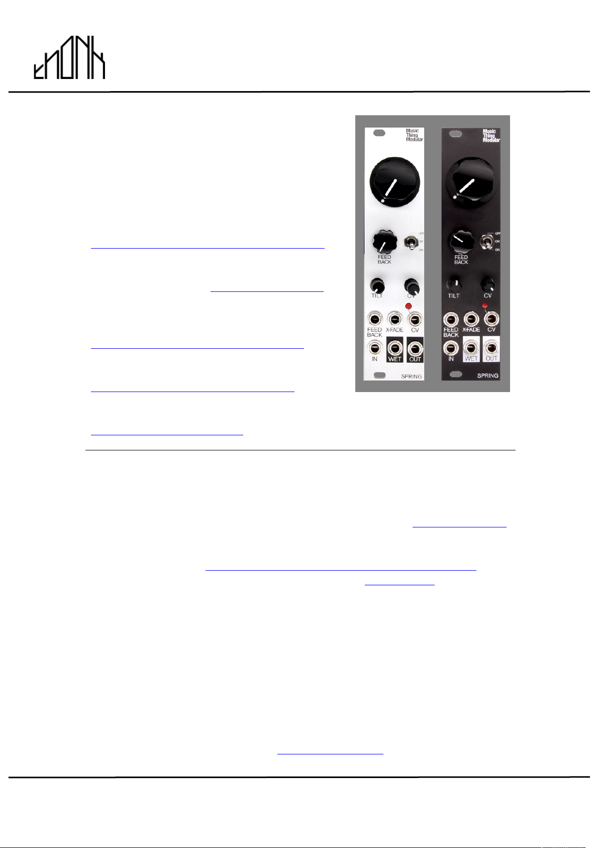
Music Thing Modular Spring
Reverb Mkii version
PLEASE DO NOT LINK TO OR REDISTRIBUTE THIS
DOCUMENT WITHOUT PERMISSION FROM THONK
For the most recent version of this
document please visit –
https://thonk.co.uk/documents/springreverb/
Refer also to the Music Thing
documentation here - http://bit.ly/2hwUvvq
For all technical support please create a
Github account and log an issue here -
https://www.thonk.co.uk/spring-github/
Chat about the build here –
https://www.thonk.co.uk/spring-muff/
All Thonk kits are sold under our standard Terms and Conditions -
http://www.thonk.co.uk/faq/
DIY INSTRUCTIONS
This document gives detailed instructions that assume you have purchased a
complete Music Thing Modular Spring Reverb MkII kit from www.thonk.co.uk
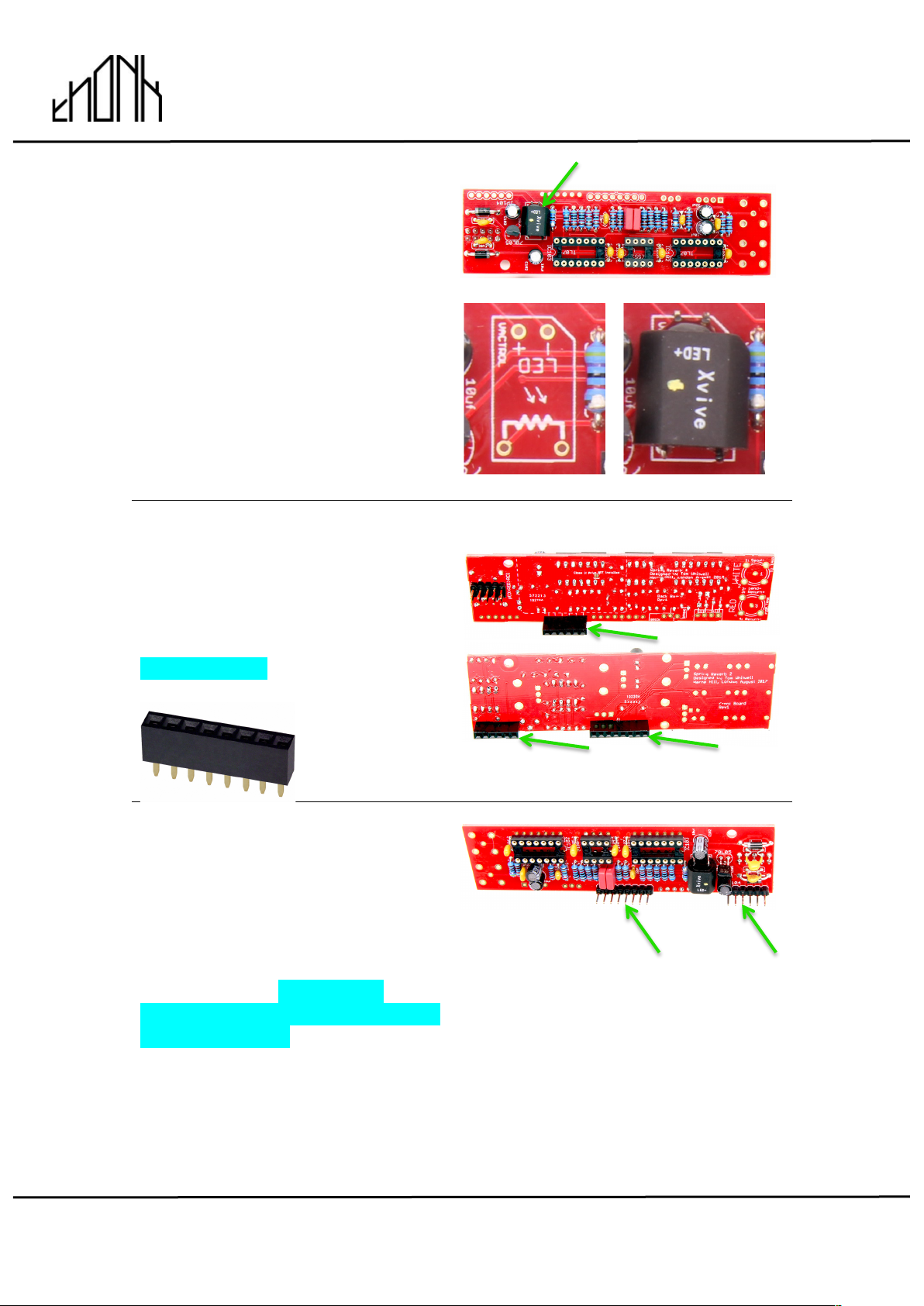
after November 2017, it also assumes no previous knowledge of electronics.
To learn to solder try https://www.youtube.com/watch?v=IpkkfK937mU and
the Adafruit guide to excellent soldering – http://bit.ly/1l77tF4
Watch and understand that whole YouTube video! If you’re not achieving the
results shown in the video then you need to buy new tools or seek advice.
You will not end up with a working unit otherwise.
TOOLS REQUIRED
Soldering iron, snipe nose pliers, wire strippers, small flat head screwdriver
and diagonal cutters AKA snips AKA side-cutters. A Digital Multimeter is
always helpful for checking for bad solder joints and continuity. Thonk sell a
range of inexpensive tools here - http://bit.ly/1jxqF3n

November 13th 2017 www.thonk.co.uk 2
Spring Reverb Mk ii
(November 2017 onwards)
Eurorack DIY Kit
Instructions
Version 1.00
SOLDER JOINTS
Your solder joints should look like those shown as ‘OK’ below, they should
have that neat conical shape on BOTH sides of the PCB. If they don’t look
the same on both sides then stop! Work out why from the soldering guides
linked and don’t continue until you are getting those results.
This isn’t about perfectionism, you are very likely to end up with a destroyed,
damaged or defective unit if you’re not hitting that standard.
This photo is from the Adafruit guide to excellent soldering -
http://bit.ly/1l77tF4 and is reproduced under an Attribution-Sharealike
creative commons license - http://creativecommons.org/licenses/by-sa/3.0/
IDENTIFYING RESISTORS
We are now shipping resistors in shared bags to save on the amount of
plastic contained in our kits, to stop less of it ending up in the ocean we
hope… but hopefully without making our builds harder to complete.
We always make sure that the resistors are grouped together in different
amounts so it’s hard to mix them up as long as you can count…
We highly advise the practice of testing one resistor of each value with a
digital multimeter BEFORE soldering. We do this at Thonk and it reduces
build errors greatly, if you don’t have a digital multimeter buy one! Or failing
that use this colour code calculator URL instead (we always ship with 1%
resistors so band 5 is always BROWN).
https://www.digikey.co.uk/en/resources/conversion-calculators/conversion-
calculator-resistor-color-code-5-band
November 13th 2017 www.thonk.co.uk 3
Spring Reverb Mk ii
(November 2017 onwards)
Eurorack DIY Kit
Instructions
Version 1.00
SPRING REVERB BUILD INSTRUCTIONS
1.
To start with we advise emptying
the bags into two separate bowls or
containers so it makes it easier to
find parts.
This document has hi-res images.
ZOOM IN for a closer look
2.
There are two PCBs included in the
kit, FRONT and BACK as shown.
We will be soldering components to
both boards during the build so
care must be taken to not absent-
mindedly solder parts to the wrong
board!
BACK PCB
FRONT PCB
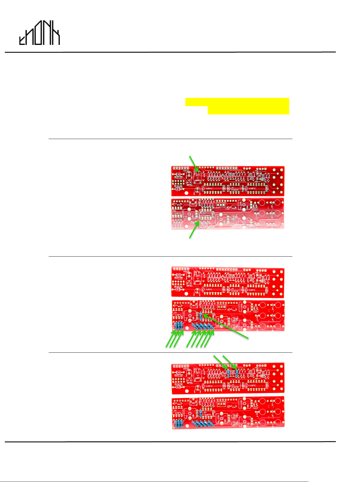
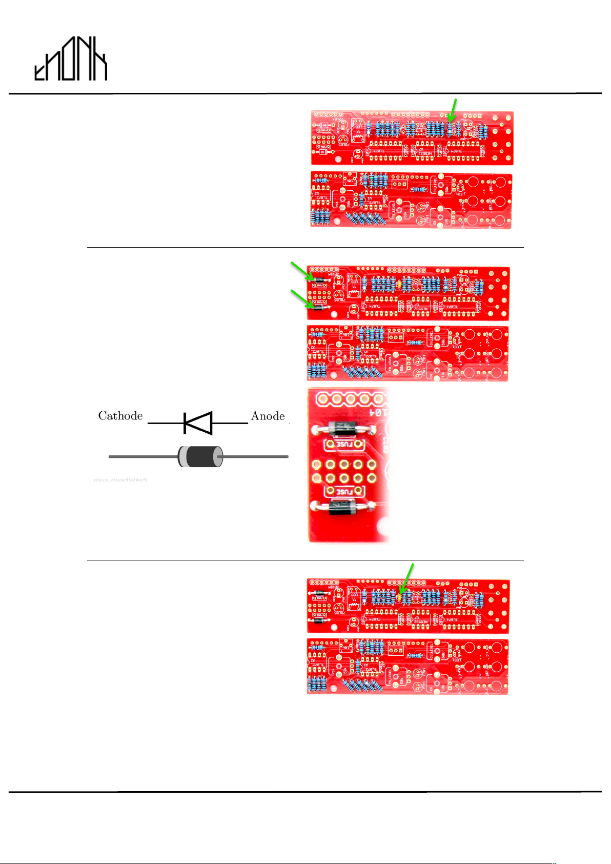
3.
First identify the resistor bag with
the nine 100K resistors and solder
into the positions shown on the
FRONT PCB
R4, R5, R8, R9, R12, R13, R21,
R22, R23
4.
In the same bag you’ll also find two
6.8K resistors, solder them into the
positions R11 and R19 shown on
the BACK PCB
November 13th 2017 www.thonk.co.uk 4
Spring Reverb Mk ii
(November 2017 onwards)
Eurorack DIY Kit
Instructions
Version 1.00
5.
Finally in that resistor bag you will
have a single 15k resistor left,
solder it into position R26 shown on
the FRONT PCB
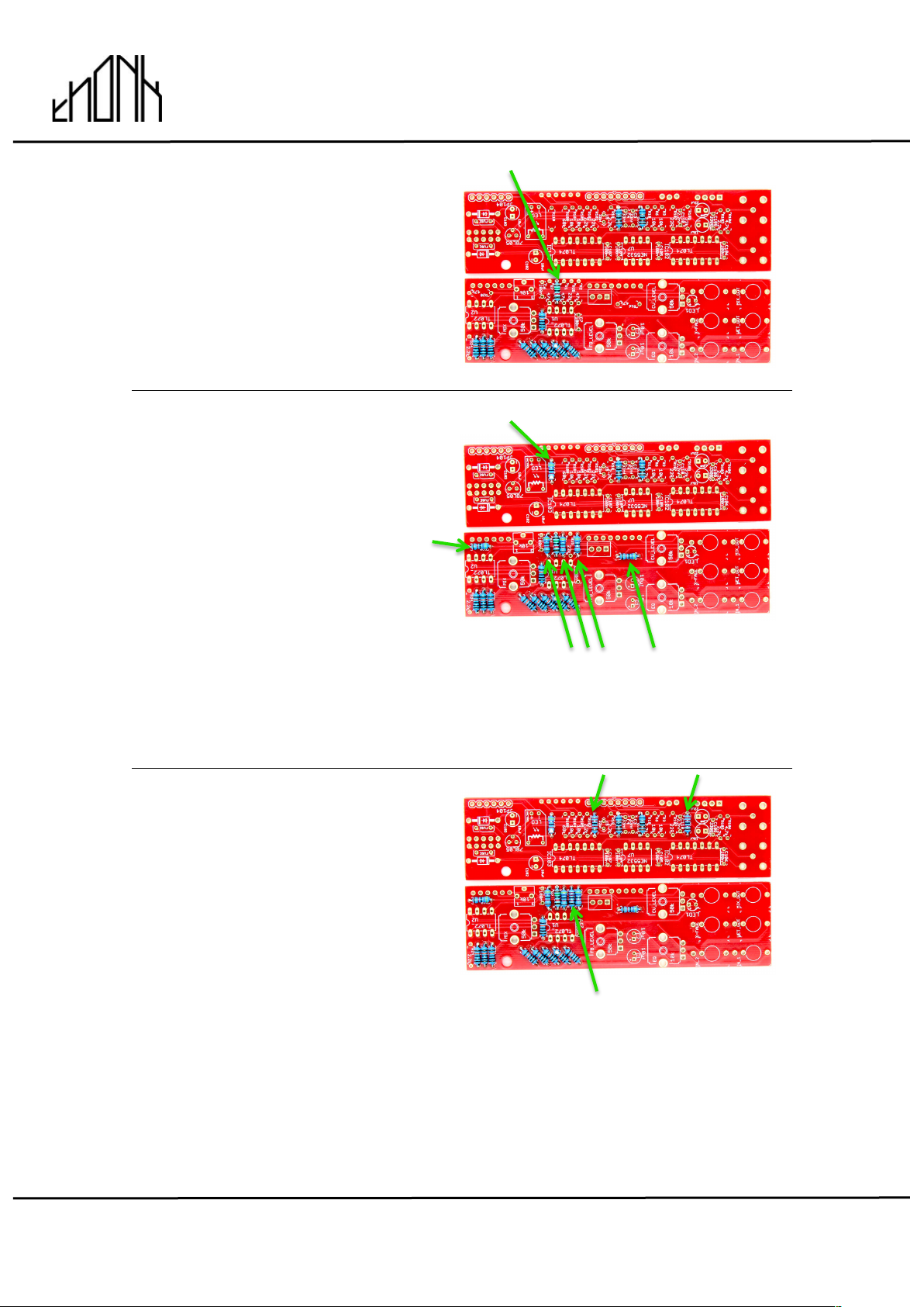
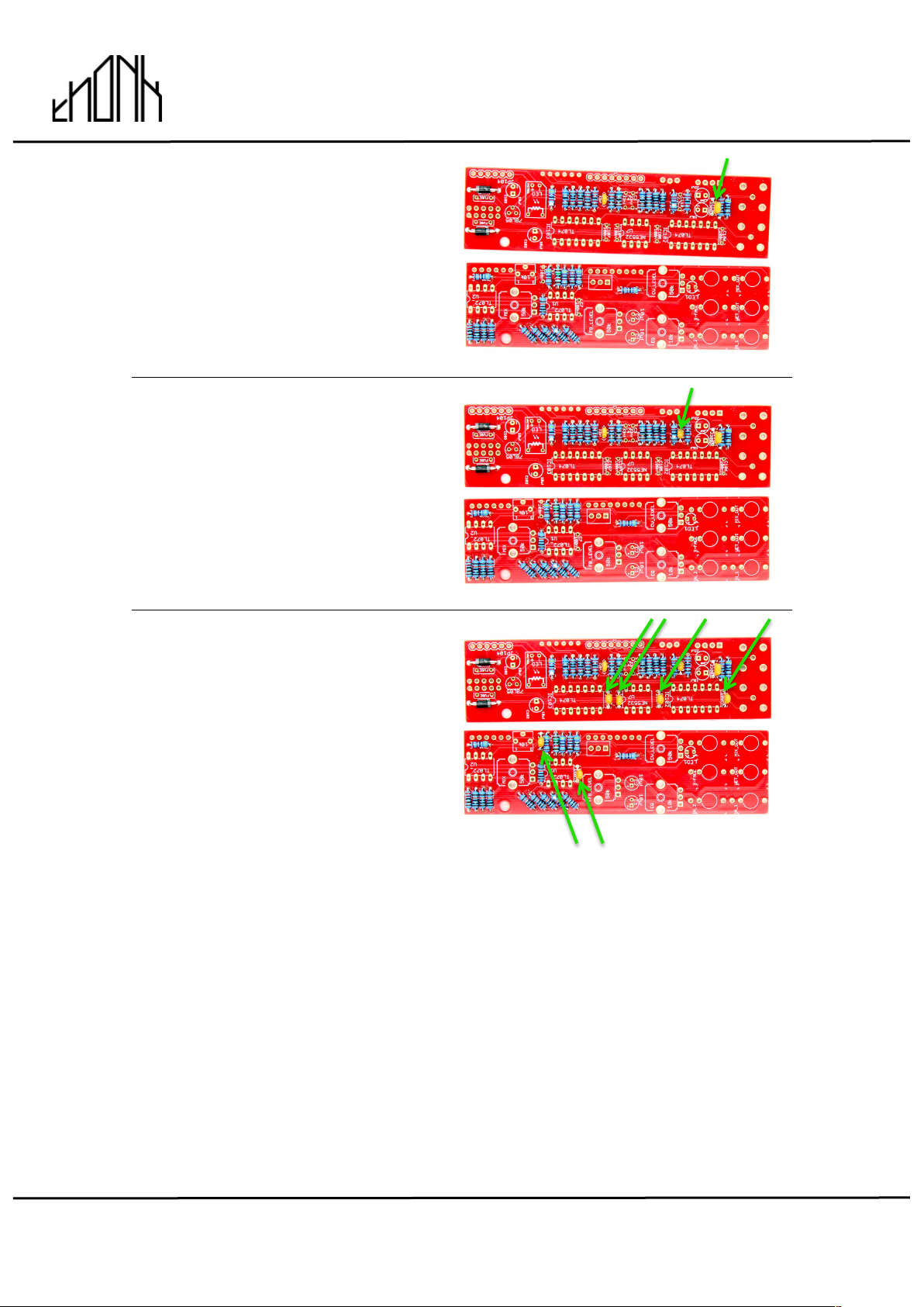
6.
Next identify the resistor bag
containing the six 47K resistors and
solder into the positions shown on
BOTH PCBs
R1, R2, R7, R16, R20, R110
NOTE! The resistance value for
R110 is not labeled as the value
depends on the type of Vactrol
used, for Thonk kits or when using a
VTL5C3 vactrol this should be a
47K resistor.
7.
In the same bag you’ll also find
three 22K resistors, solder them
into the positions R25, R101 and
R109
shown on the BOTH PCBs
November 13th 2017 www.thonk.co.uk 5
Spring Reverb Mk ii
(November 2017 onwards)
Eurorack DIY Kit
Instructions
Version 1.00
8.
Finally in that resistor bag you will
have a single 68K resistor left,
solder it into position R108 shown
on the BACK PCB
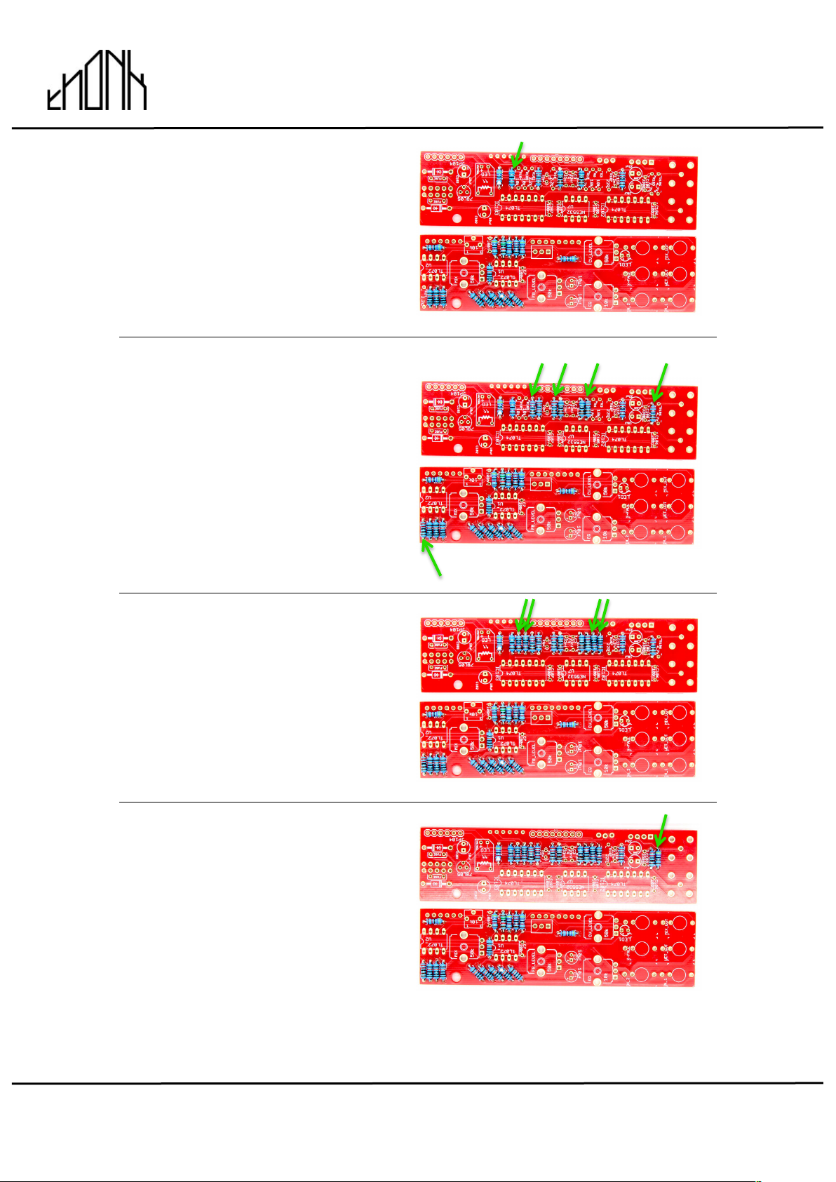
9.
Next identify the resistor bag
containing the five 2.2K resistors
and solder into the positions shown
on BOTH PCBs
R10, R18, R24, R102, R103
10.
In the same bag you’ll also find four
10K resistors, solder them into the
positions R3, R6, R104 and R105
shown on the BACK PCB
11.
Finally in that resistor bag you will
have a single 4.7K resistor left,
solder it into position R106shown
on the BACK PCB
November 13th 2017 www.thonk.co.uk 6
Spring Reverb Mk ii
(November 2017 onwards)
Eurorack DIY Kit
Instructions
Version 1.00
12.
Next identify the bag containing the
single 22R resistor and solder into
position R107 on the BACK PCB
This bag also contains a diode and
a capacitor.
13.
Solder the two 1N4001 diodes from
the same bag into the positions as
shown.
NOTE! Orientation of this part is
vital, the module will not work if they
are the wrong way round.
14.
Finally find the single 22pF
capacitor in the same bag and
solder into position C5 on the
BACK PCB
November 13th 2017 www.thonk.co.uk 7
Spring Reverb Mk ii
(November 2017 onwards)
Eurorack DIY Kit
Instructions
Version 1.00
15.
Next find the bag with the single
3300pF capacitor and solder into
position C108 on the BACK PCB
16.
Next find the bag with the single
2.2nF capacitor and solder into
position C110 on the BACK PCB
17.
Next find the larger bag of various
caps and identify the 6 x 100n
capacitors and solder into the
positions shown on BOTH PCBs
C6, C7, C104, C105, C106, C107
November 13th 2017 www.thonk.co.uk 8
Spring Reverb Mk ii
(November 2017 onwards)
Eurorack DIY Kit
Instructions
Version 1.00
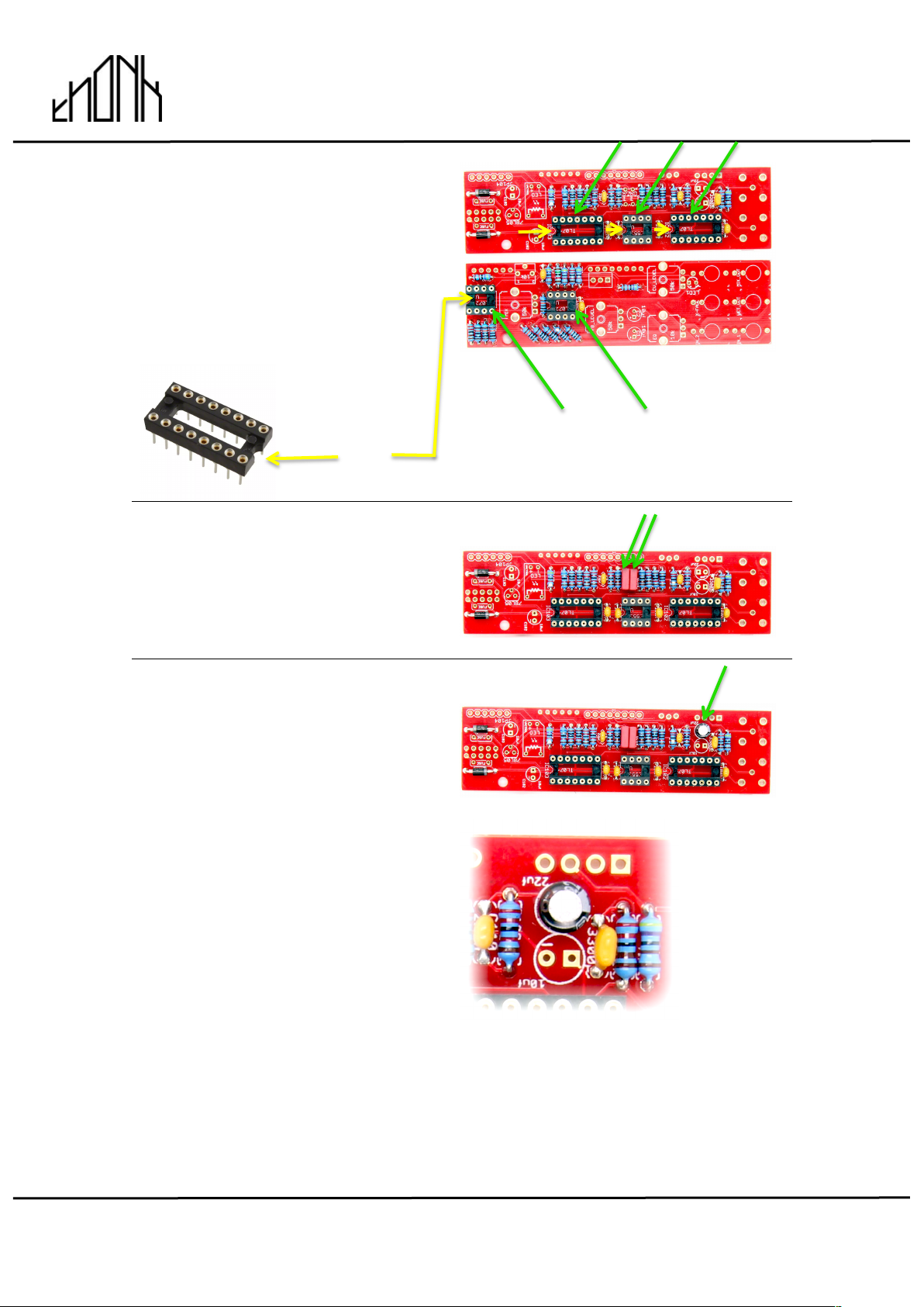
18.
Next find the larger bag of
mechanical parts and pull out the
five IC Sockets.
Make sure the notches in the
sockets match the notches on the
silkscreen. Solder to BOTH PCBs
19.
Return to the cap bag and find the
two Red 33nF Polybox caps and
solder into positions C3 & C4
20.
Return to the cap bag and find the
single 22uF electrolytic cap. Make
sure to identify the different caps by
the value written on them! Solder
into position C109.
NOTE! The orientation is vital, the
shorter lead on the component
should go to the circular pad
marked with a minus ‘-‘ on the PCB.
Note the component has a grey
stripe on the cylindrical body on the
minus side, the grey stripe should
be facing the adjacent yellow
ceramic cap.
notch

November 13th 2017 www.thonk.co.uk 9
Spring Reverb Mk ii
(November 2017 onwards)
Eurorack DIY Kit
Instructions
Version 1.00
21.
Next find the square blue 10K
trimmer and solder into the position
shown on the FRONT PCB
22.
Return to the cap bag and find the
five 10uF electrolytic caps. Make
sure to identify the different caps by
the value written on them! Just take
three of them for now and solder
into positions C101, C102, C103 on
the BACK PCB
NOTE! The orientation is vital, the
shorter lead on the component
should go to the circular pad
marked with a minus ‘-‘ on the PCB.
Note the component has a grey
stripe on the cylindrical body on the
minus side.
23.
Now grab the remaining two 10uF
electrolytic caps and solder into
positions C1 and C2 on the FRONT
PCB
NOTE! The orientation is vital, the
LONGER lead on the component
should go to the square pad
marked with a plus ‘+‘ on the PCB.
The grey stripe on the cylindrical
body should face the center of the
FRONT PCB
THESE CAPS ARE MARKED
DIFFERENTLY - With a PLUS
sign!
November 13th 2017 www.thonk.co.uk 10
Spring Reverb Mk ii
(November 2017 onwards)
Eurorack DIY Kit
Instructions
Version 1.00
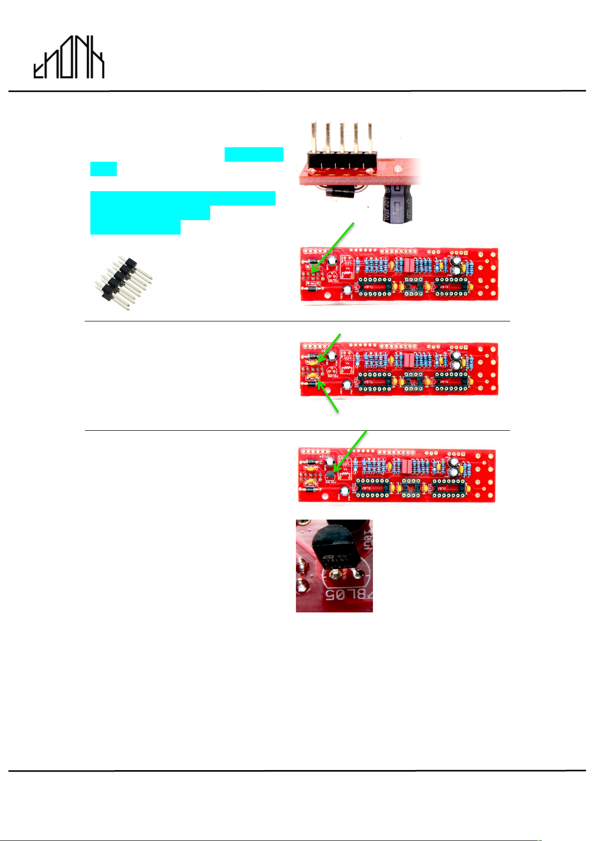
24.
Locate the 10 pin Eurorack power
header and solder to the OPPOSITE
SIDE of the BACK PCB
DO NOT SOLDER TO THE SAME
SIDE AS THE OTHER
COMPONENTS!
25.
Next find the small bag containing
the FUSES and solder into the two
positions shown, inbetween the two
Diodes.
26.
Open the silver IC bag with yellow
ESD sticker (read the warning) and
find the 78L05 voltage regulator and
solder into the position shown on the
BACK PCB
NOTE! The orientation is vital, the
curved body of the component
must match the curved outline on
the silkscreen. Take care to solder
efficiently and quickly so as to not
heat the component for too long.
November 13th 2017 www.thonk.co.uk 11
Spring Reverb Mk ii
(November 2017 onwards)
Eurorack DIY Kit
Instructions
Version 1.00
27.
Next identify the VTL5C3 Vactrol
and solder into position as shown
on the BACK PCB
NOTE! The orientation is vital, make
sure the LED text on the component
matches the LED text on the PCB.
28.
Next you will solder the female
headers to the rear of BOTH PCBs
Take care to not solder them on the
WRONG SIDE!
29.
Next take the male pin header and
break down into one 6 pin section
and one 8 pin section.
Solder into the positions shown on
the REAR PCB, take care to
solder them on the SAME SIDE as
the resistors etc.
November 13th 2017 www.thonk.co.uk 12
Spring Reverb Mk ii
(November 2017 onwards)
Eurorack DIY Kit
Instructions
Version 1.00
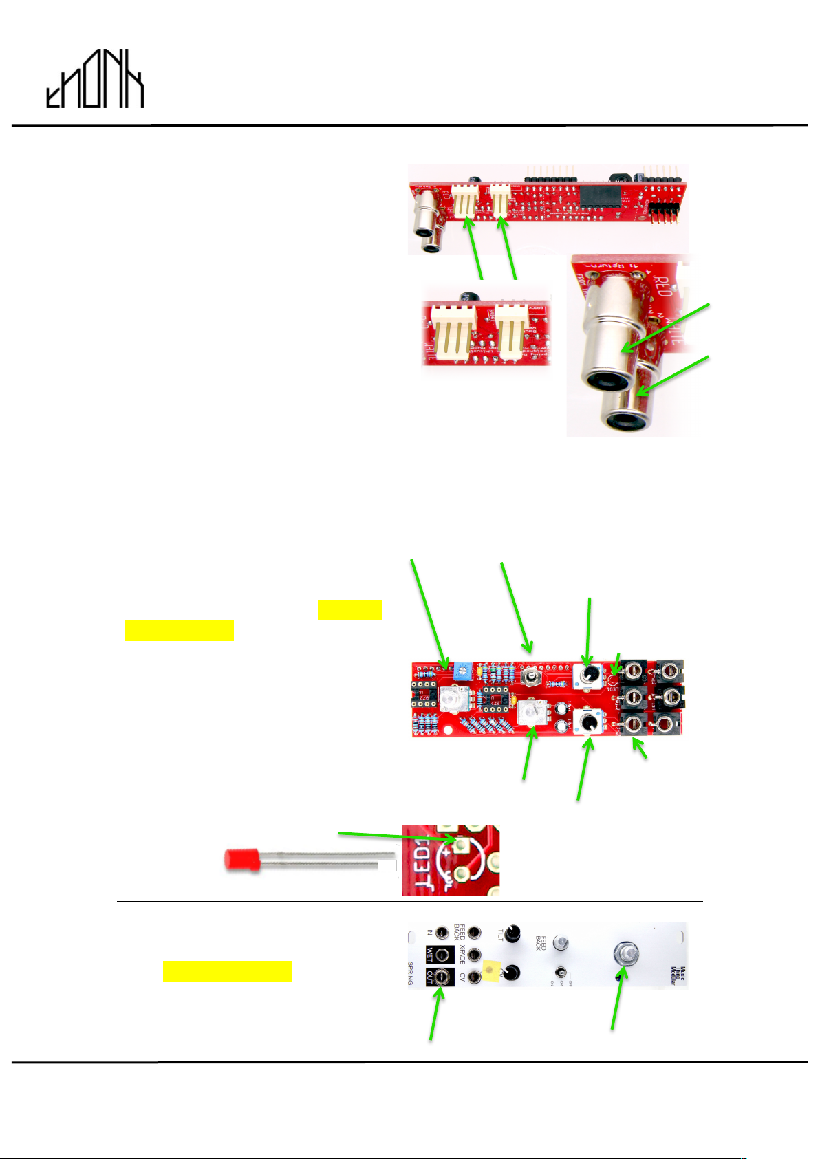
30.
Next find the two cream coloured
MTA expansion headers, one
three pin and one four pin and
solder to the back on the REAR
PCB in the positions and orientation
shown.
NOTE! The orientation is vital, make
sure the pins are exposed towards
on the edge of the PCB as shown.
Then solder the two RCA phono connectors as shown.
If you are planning to use the expander module with
the RCA’s mounted on the front panel we still recommend soldering them.
Even when unused these rear phonos only add 3mm more depth to the
module compared to the power cable.
31.
Position all the parts in section 42.
as shown on the PCB but DO NOT
SOLDER YET!
Take care to get the B50K and
B10K trimmer pots the right way
round. Take the nuts off the jacks
and pots.
NOTE! The longer lead of the LED
MUST go to the pad marked with
a + on the PCB silkscreen.
Green Pot Red Switch
B50K Trimmer
(CV Level)
LED
Jacks
Green Pot
B10K Trimmer
(EQ)
32.
Now before soldering put the
panel on carefully and secure in two
places with nuts as shown.
November 13th 2017 www.thonk.co.uk 13
Spring Reverb Mk ii
(November 2017 onwards)
Eurorack DIY Kit
Instructions
Version 1.00
33.
In order to fit the top flat face of the
LED flush with the panel we
recommend using masking tape to
hold its position before soldering.
You can now solder all pots, jacks
the LED and the switch. Don’t miss
any joints! Remove the panel again
when you are done.
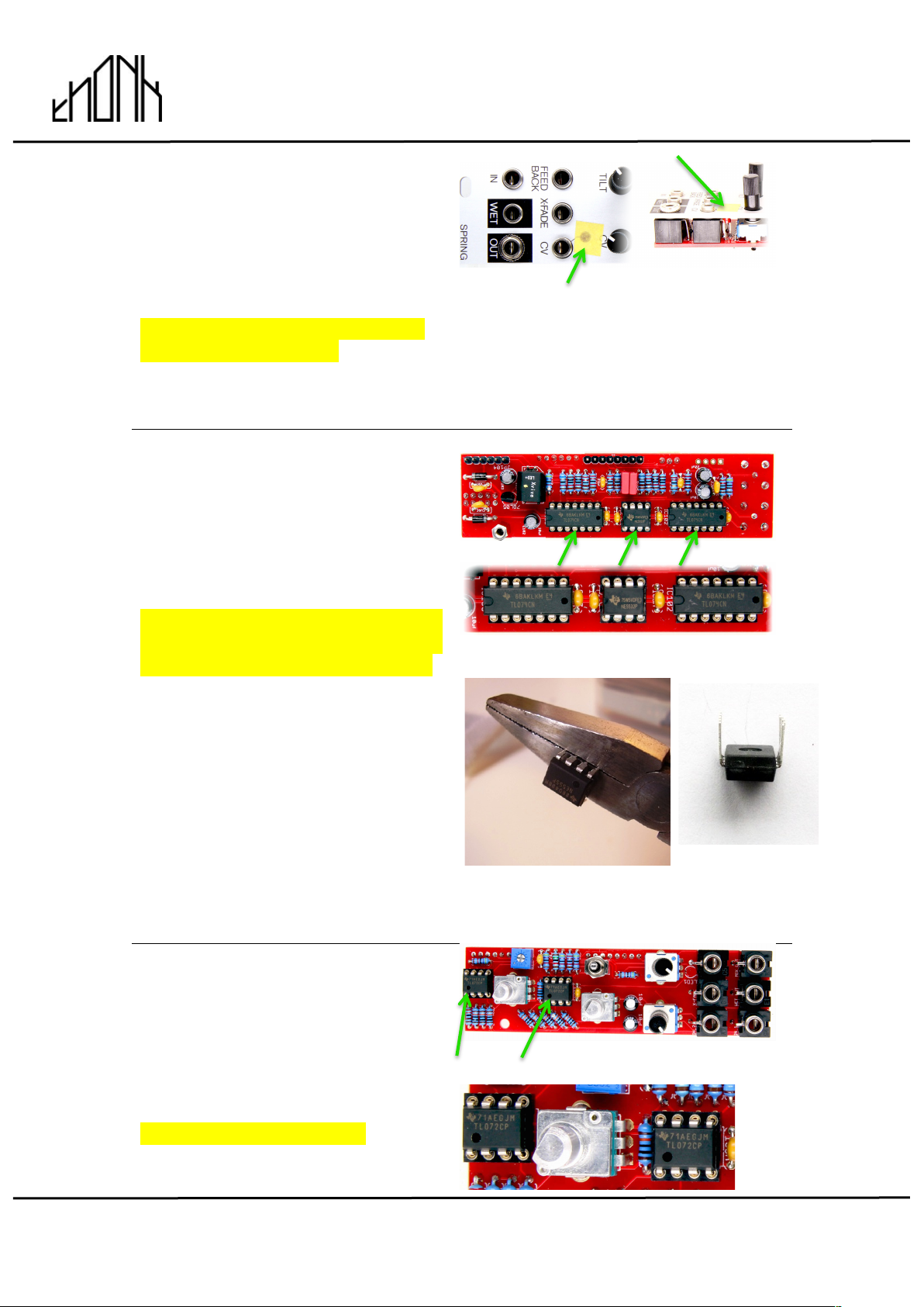
34.
Go back to the IC packet and find
the two TL074CN and the single
NE5532P and position as shown on
the BACK PCB
NOTE – Orientation is vital! Make
sure the notches in the ICs match
the notches on the PCB silkscreen.
NOTE!You will need to bend the
pins on the IC inwards slightly so
they are at 90 degrees to the body
of the chip. They will come slightly
splayed out. This can be done
safely by clasping the 4 pins in a
pair of pliers (not the cutting edge
near the pivot joint though!) and
very gently bending inwards
together. Repeat for the other side.
35.
Take the final two TL072CP ICs and
position as shown on the FRONT
PCB, the circle on the face should
be at the notch end of the socket.
NOTE – Orientation is vital!
November 13th 2017 www.thonk.co.uk 14
Spring Reverb Mk ii
(November 2017 onwards)
Eurorack DIY Kit
Instructions
Version 1.00
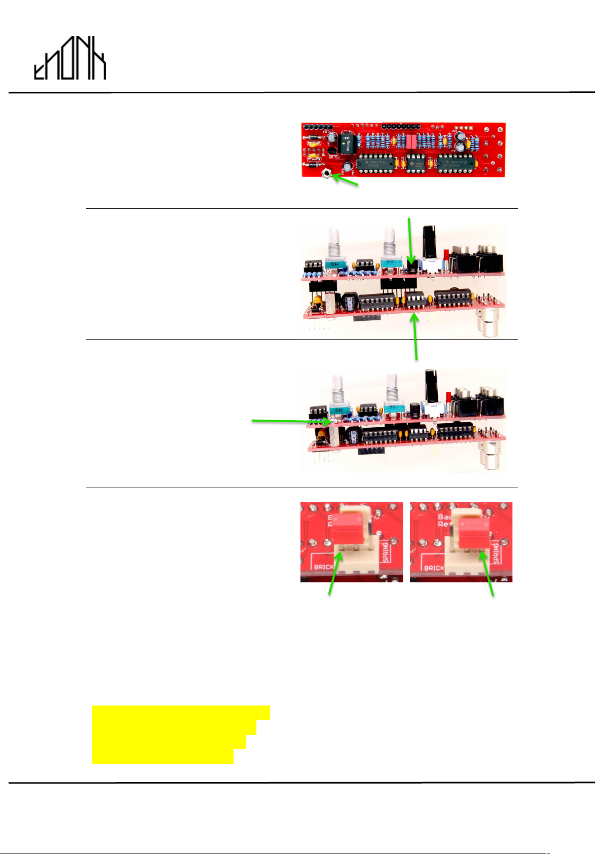
36.
Affix the hex post to the REAR PCB
with one of the M3 screws
provided.
37.
Now you will sandwich the two
PCBs together like so, mating the
male and female headers.
Secure the hex post with another
M3 screw to hold the boards
together.
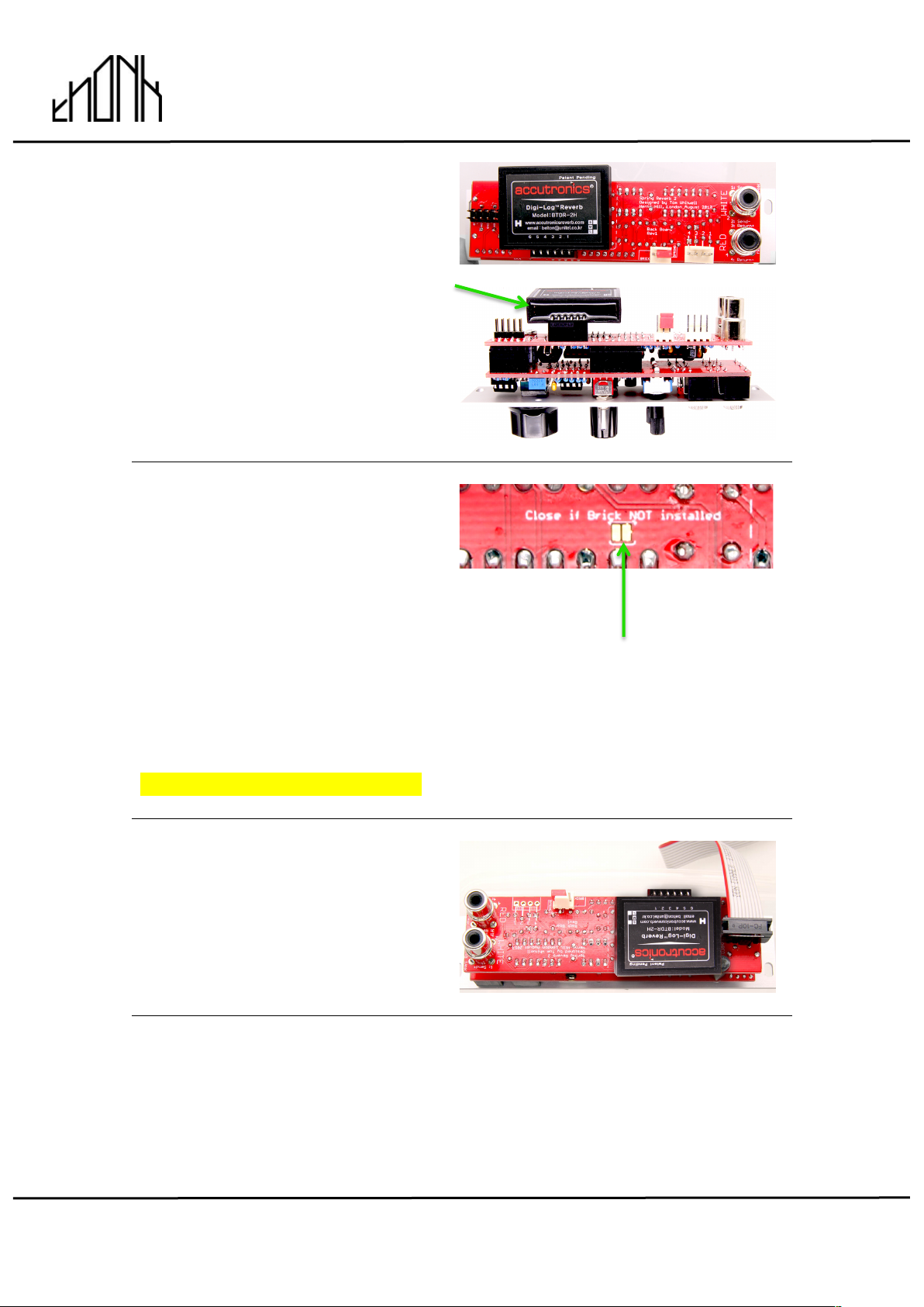
38.
If you are not installing the expander
you need to position the red shunt
on the 3 pin expander header. This
chooses either the external real
spring tank OR the digital brick
attached to the back of the module.
The expander allows you to blend
and crossfade between the real
tank and digital brick to dial in a
Custom response.
Attach the shunt even if you ARE
attaching the expander as you
should test the main module
without the expander first.
FOR DIGITAL FOR REAL SPRING
BRICK TANK
(ON RCA
CONNECTION)
November 13th 2017 www.thonk.co.uk 15
Spring Reverb Mk ii
(November 2017 onwards)
Eurorack DIY Kit
Instructions
Version 1.00
39.
If you are fitting the digital brick you
position it without soldering like so
on the back of the module.
40.
If you have no intention of ever
using the digital brick you can
choose to solder this optional point
(bridge a blob of solder between the
two pads). This grounds the brick
op amp, so it’s not floating and
potentially oscillating. We have
never experienced any problems
when NOT doing this, so we don’t
strictly recommend it as it’ll be
awkward to undo.
If in doubt DON’T solder this pad.
41.
Position the power cable like so,
with the red stripe towards the
center of the PCB.
42.
If you are not using an external ‘real’ spring tank then you are ready to power
on the module. If you are connecting a real tank or building the expander
then please continue or maybe take a rest from soldering :)
November 13th 2017 www.thonk.co.uk 16
Spring Reverb Mk ii
(November 2017 onwards)
Eurorack DIY Kit
Instructions
Version 1.00
43.
For real spring tank continue.
Even if you plan to build the
expander with external RCA’s
it’s best to test with the onboard
RCA jacks first.
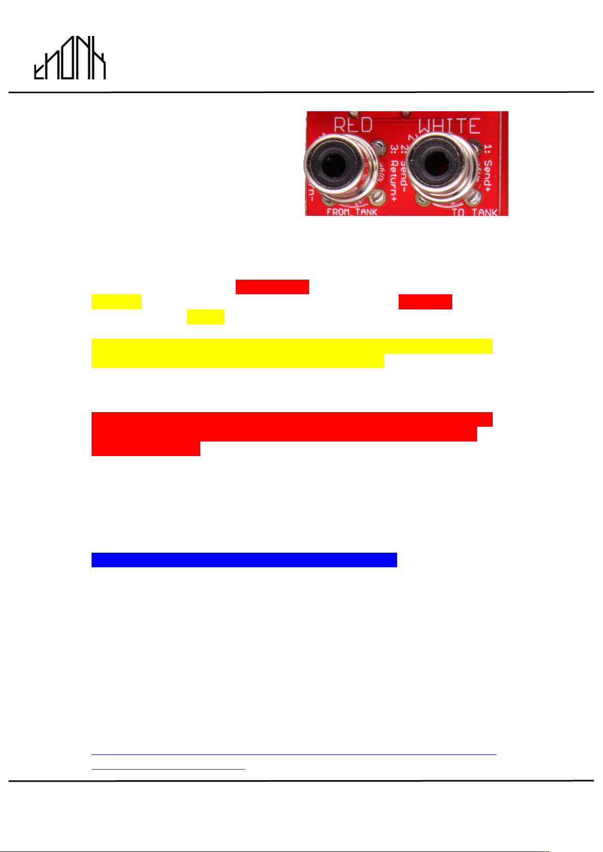
Note that there isn’t any strict convention between spring tank manufacturers
on red and white phono jacks. Sometimes red is input, sometimes output. So
it’s best to just follow the text on the PCB.
The left hand jack marked FROM TANK should be connected to the
OUTPUT of the spring tank. The right hand jack marked TO TANK should be
connected to the INPUT of the spring tank.
NOTE! Spring reverb tanks are inherently senstive to picking up noise
and hum from power supplies or other electronics. While it is tempting to
build the tank inside your Eurorack case it can be very difficult or impossible
to stop it picking up a lot of noise from the other electronics.
When first testing your module we suggest you put the spring tank as
far away as possible from your eurorack case or other electrical or
electronic devices.
Once your tank is connected, power on! Even if you are building the
expander you should test the main module first before connecting it.
CALIBRATION
Calibration doesn’t need specialist tools, just your EARS
If you are using a real spring tank then before putting the big knob on the
module you will want to use a small screwdriver to adjust the trimmer.
This trimmer controls the wet reverb level of the REAL spring tank only. It
does not affect the gain of the digital brick reverb.
We advise feeding the loudest sine wave available to the reverb module input
and then patch into the wet output only. Adjust the trimmer level until you
can hear the reverb start to distort and then wind it back a little bit. You may
want to adjust it again later on but this is a good place to start.
For more information on this module and selecting a suitable tank read here -
https://medium.com/music-thing-modular-notes/everything-i-know-about-
spring-reverb-1fb4b32abf87

November 13th 2017 www.thonk.co.uk 17
Spring Reverb Mk ii
(November 2017 onwards)
Eurorack DIY Kit
Instructions
Version 1.00
Table of contents
Other Thonk Recording Equipment manuals


