9
Subject to change without notice
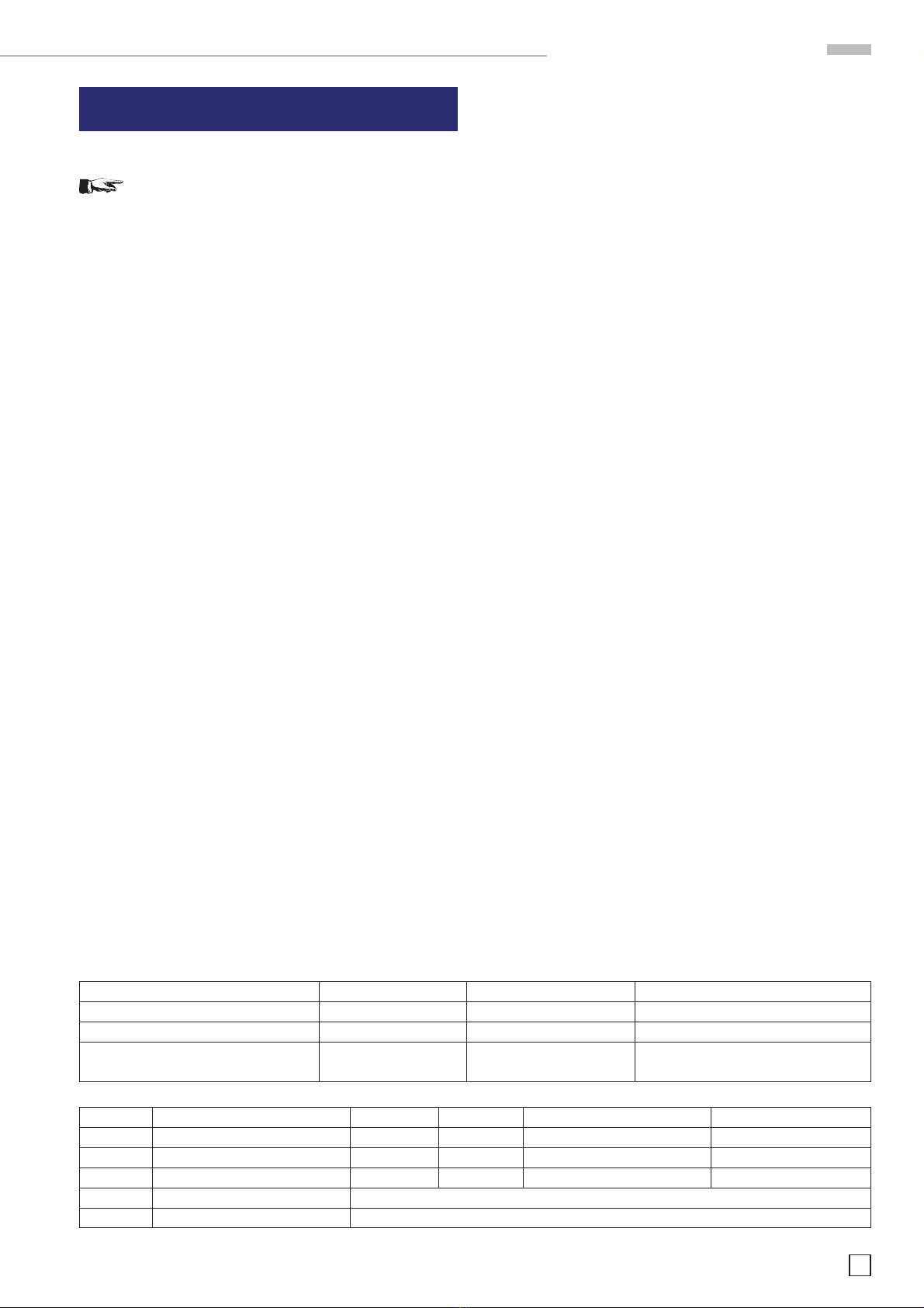
class adress range net quota host quota max. number of networks max. number of hosts
A 0.0.0.1 - 127.255.255.255 8 Bit 24 Bit 126 16.777.214
B 128.0.0.1 - 191.255.255.255 16 Bit 16 Bit 16.384 65.534
C 192.0.0.1 - 223.255.255.255 24 Bit 8 Bit 2.097.151 254
D 224.0.0.1 - 239.255.255.255 Reserved for multicast applications
E 240.0.0.1 - 255.255.255.255 Reserved for special applications
Table 2: Classes of IP adresses
Table 1: Private IP adress ranges
adress range subnetz mask CIDR way of writing number of possible host adresses
10.0.0.0 –10.255.255.255 255.0.0.0 10.0.0.0/8 224 − 2 = 16.777.214
172.16.0.0 –172.31.255.255 255.240.0.0 172.16.0.0/12 220 − 2 = 1.048.574
192.168.0.0 –192.168.255.255 255.255.0.0 192.168.0.0/16 216 − 2 = 65.534
255.255.255.0 192.168.0.0/24 281− 2 = 254
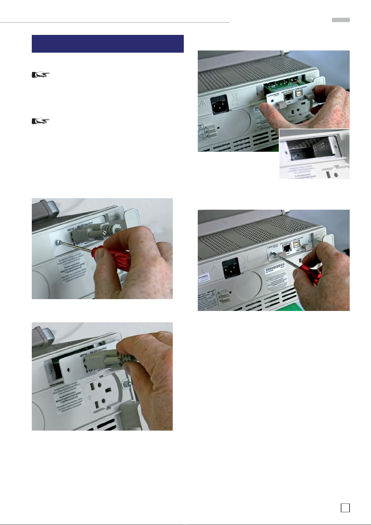
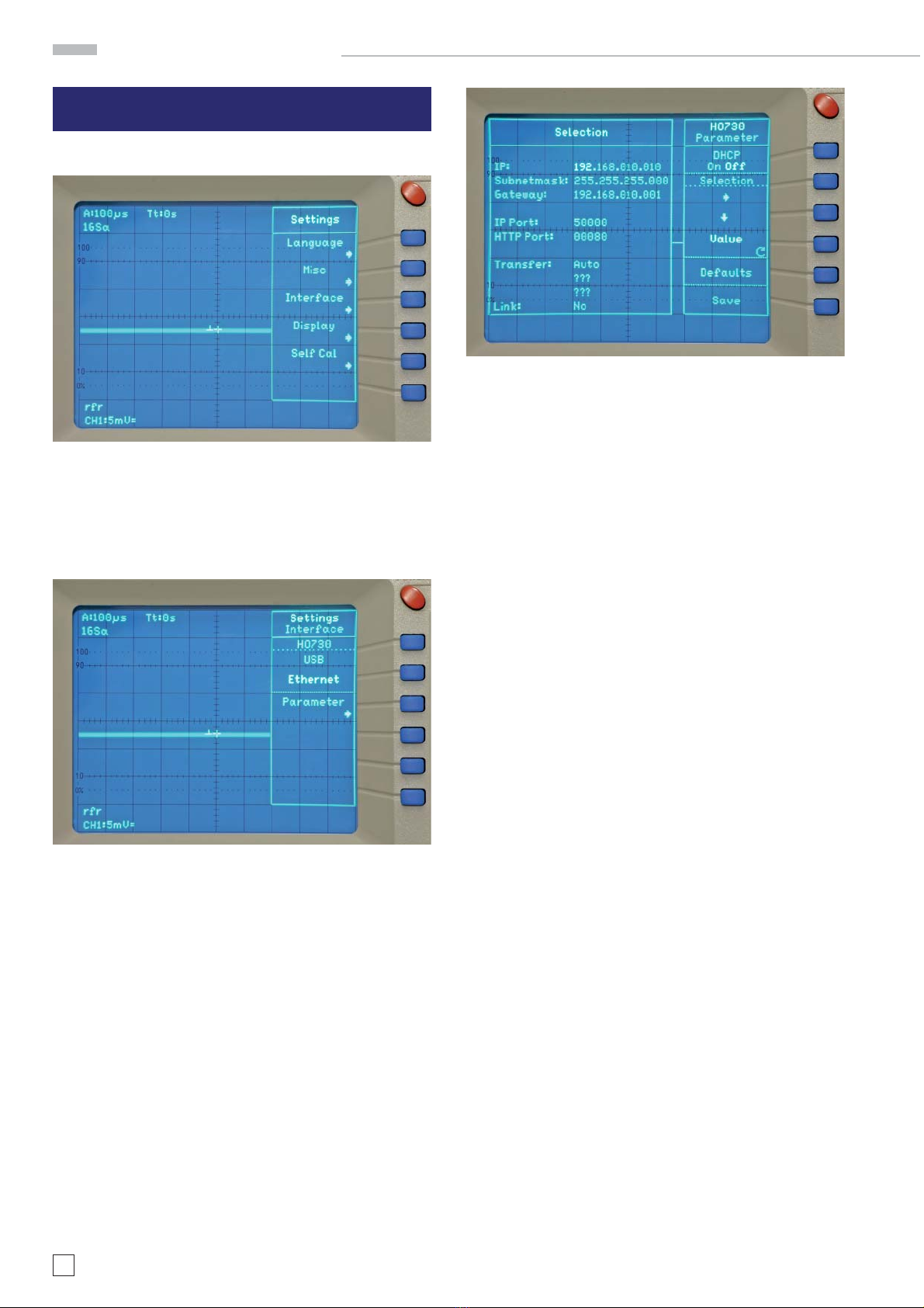
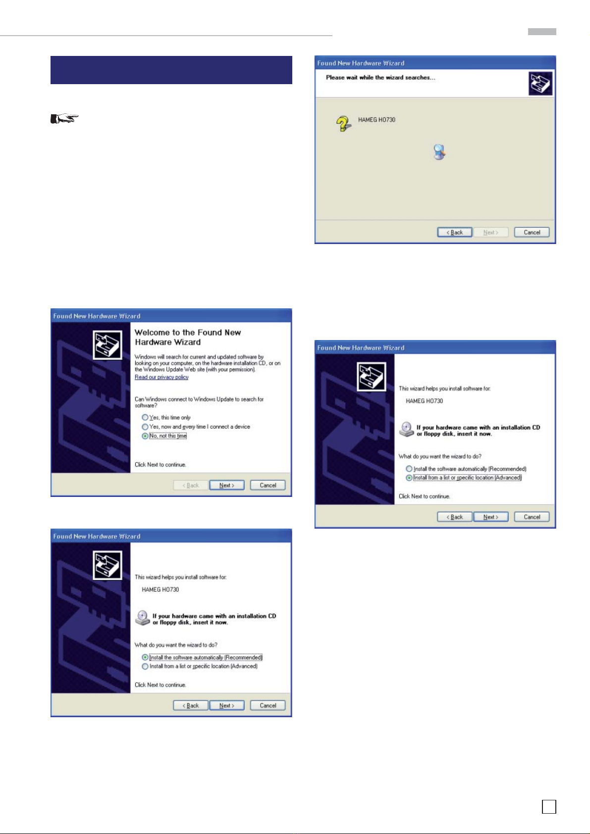
8. Ethernet configuration
Reference!
The host (PC) must have an Ethernet LAN interface
inserted. For the configuration of this interface you
will find further information in its PC manual or in
the manual of your network interface.
8.1 IP networks (IP – Internet protocol)
In order that two or several network elements (e.g. measuring
instruments, host/PC‘s, …) can communicate over a network
with one another, some fundamental connections have to be
considered, so that data communication is error free and un-
impaired.
For each element in a network an IP address has to be assigned,
so that they can exchange data among themselves. IP addresses
are represented (with the IP version 4) as four decimal numbers
separated by points (e.g. 192.168.15.1). Each decimal number
is represented by a binary number of 8 bits. IP addresses are
divided into public and private address ranges. Public IP addres-
ses will be able to route by the Internet and an Internet service
Provider (ISP) can to be made available. Public IP addresses
can be reached directly over the Internet to directly exchange
internet data. Private IP addresses are not routed by the Internet
and are reserved for private networks. Network elements with
private IP addresses cannot be reached directly over the Internet
so no data can be directly exchanged over the Internet. To allow
network elements with a private IP address to exchange data
over the Internet, they require a router for IP address conversion
(English NAT; Network address translation), before connection
to the Internet. The attached elements can then data exchange
over this router, which possesses a private IP address (LAN IP
address) and also a public IP address (WAN IP address), via the
Internet. If network elements exchange data only over a local
network (without connection with the Internet), appropriate use
private IP addresses. Select in addition e.g. a private IP address
for the oscilloscope and a private IP address for the host (PC),
with which you would like to control the oscilloscope. If you
might connect your private network with the Internet later via
a router, the private IP addresses used in your local network
can be maintained. Since within each IP address range the
first IP address is used as network IP address and the last IP
address is used as Broadcast IP address, in each case two IP
addresses have to be taken off from the “number of possible
host addresses“ (see table 1: Private IP address ranges).
Apart from the organization of IP addresses into public and pri-
vate address ranges, IP addresses are also divided into classes
(Class: A, B, C, D, E). Within the classes A, B, and C are also
include the private IP of address ranges described before. The
categorisation from IP addresses is for the assignment of public
IP address ranges of importance and essentially depends on
the size of a local network (maximum number of hosts in the
network), which is to be connected with the Internet (see table
2: Classes of IP addresses).
IP addresses can fix (statically) or variable (dynamically) to be
assigned. If IP addresses in a network are assigned fix, an IP
address must be preset manually with each network element.
If IP addresses in a network are assigned to the attached
network elements automatically (dynamically), a DHCP server
(English DHCP becomes; Dynamic Host Configuration Protocol)
is required for the dispatching of IP addresses. With a DHCP
server an IP address range for the automatic dispatching of
IP addresses can be preset. A DHCP server is usually already
integrated in a router (DSL router, ISDN router, Modem router,
WLAN router, …) integrated. If a network element (e.g. an oscil-
loscope) is connected by a network cable directly with a host
(PC), the IP addresses cannot be assigned to the oscilloscope
and the host (PC) automatically, since no network with DHCP
server is present here. They have to be preset therefore at the
oscilloscope and at the host (PC) manually.
IP addresses are divided by using subnet mask into a network
quota and into a host quota, so similarly e.g. a telephone number
is divided in pre selection (land and local area network number)
and call number (user number). Subnet mask have the same
form as IP addresses. They are represented with four decimal
numbers separated by points (e.g. 255.255.255.0). As is the case
for the IP addresses here each decimal number represents a
binary number of 8 bits. The separation between network quota
and host quota is determined by the subnet mask within an IP
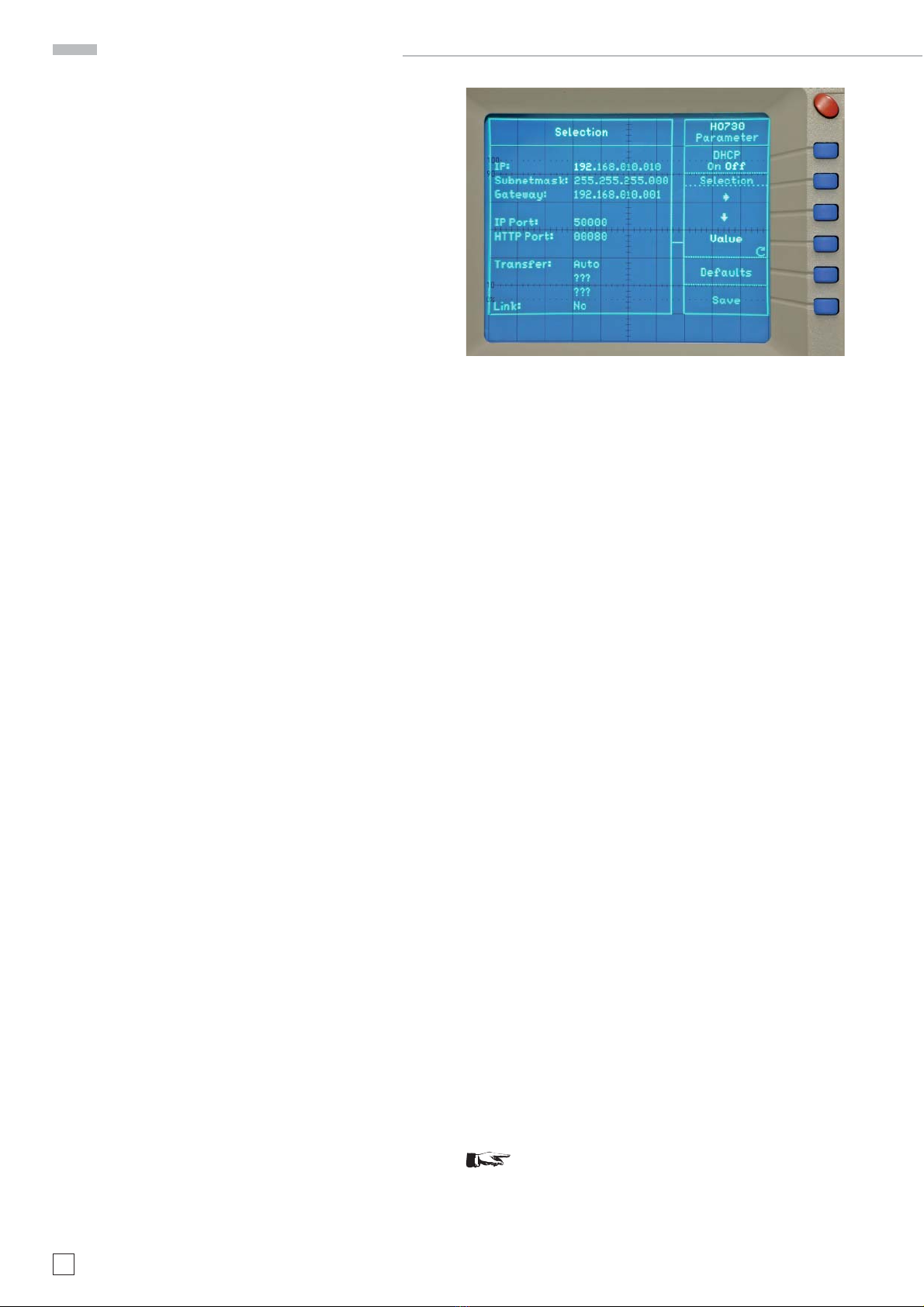
address (e.g. the IP address 192.168.10.10 by the subnet mask
255.255.255.0 is divided into a network quota 192.168.10.0 and a
host quota of 0.0.0.10). The allocation takes place via the trans-
formation of the IP address and the subnet mask in binary form
and afterwards a bit by bit one logical AND operation between
IP address and subnet mask. The result is the network quota
of the IP address. The host quota of the IP address takes place
via the bit by bit logical NAND operation between IP address
and subnet mask. By the variable allocation of IP addresses in
network quota and host quota via subnet masks, one can specify
IP address ranges individually for large and small networks.
Thus one can operate large and small IP networks and connect if
necessary to the Internet via a router. In smaller local networks
the subnet mask 255.255.255.0 is mostly used. Network quota
(the first 3 numbers) and host quota (the last number) are simple
Ethernet configuration