THOR GE559-N Owner's manual
Thor Gas Salamander
Installation and Operation Instructions
Model: GE559-N GE559-P
IMPORTANT FOR FUTURE REFERENCE
Please complete this information and retain this manual for the life of the equipment. For Warranty
Service and/or parts, this information is required.
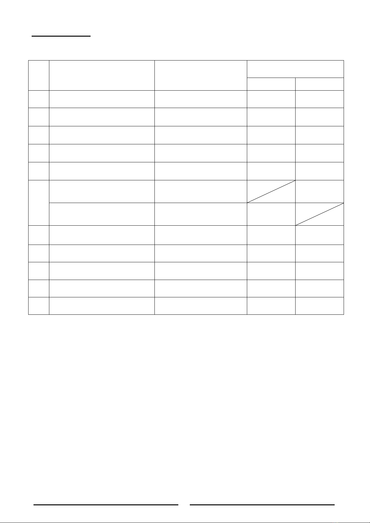
Model Number Serial Number Date Purchased
WARNING: For your safety, do not store or use gasoline or other flammable vapors or
liquids in the vicinity of this or any other appliances. Keep the area free and clear of
combustible.
WARNING :Improper installation, adjustment, alteration, service or maintenance can
cause property damage, injury, or death. Read the installation operating and maintenance
instructions thoroughly before installing, or servicing this equipment.
WARNING:Instructions must be posted in a prominent location. All safety precautions
must be taken in the event the user smells gas. Safety information can be obtained from
your local gas supplier.
15 Badgally Road, Campbelltown
NSW 2560
Thor after sales/service: 1300 225 960

Contents
Introduction
............................................................................................. 2
Specifications
........................................................................................... 3
General
Pack Contents
Gas Supply Requirements
Dimensions
................................................................................................ 4
Installation
................................................................................................ 5-9
Installation Requirements
Unpacking
Location
Clearances
Assembly
Gas Connection
Commissioning
Operation
...................................................................................................10-11
Operation Guide
Description of Controls
Lighting the Main Burner
Main burner air supply
Cleaning and Maintenance
............................................................................12
Initial cleaning
Daily Cleaning
Weekly Cleaning
Vent system
Stainless steel surface
Adjustments……………………………………………………………………………………………13
Trouble Shooting
.........................................................................................14
Replacement parts ……
........................................................................……..14
Explosion Drawing
..............................................................................……..15-16
Spare Parts List
..........................................................................................17-18

2
Introduction
We are confident that you will be delighted with your Thor Gas Salamander, and it will become a most
valued appliance in your commercial kitchen.
To ensure you receive the utmost benefit from your new Gas Salamander, there are two important things
you can do.
Firstly
:
Please read the instruction book carefully and follow the directions given. The time taken will be well
spent.
Secondly
:
If you are unsure of any aspect of the installation, instructions or performance of your appliance,
contact your dealer promptly. In many cases a phone call could answer your question.
WARNING:
IMPROPER INSTALLATION, ADJUSTMENT, ALTERATION, SERVICE OR MAINTENANCE CAN CAUSE PROPERTY
DAMAGE, INJURY OR DEATH.
READ THE INSTALLATION, OPERATING AND MAINTENANCE INSTRUCTIONS THOROUGHLY BEFORE INSTALLING OR
SERVICING THIS APPLIANCE.
WARNING:
INSTRUCTIONS TO BE FOLLOWED IN THE EVENT THE USER SMELLS GAS ARE TO BE POSTED IN A PROMINENT
LOCATION. THIS INFORMATION SHALL BE OBTAINED BY CONSULTING THE LOCAL GAS SUPPLIER.
WARNING:
GREAT CARE MUST BE TAKEN BY THE OPERATOR TO USE THE EQUIPMENT SAFELY TO GUARD IT AGAINST RISK OF
FIRE.
•
THE APPLIANCE MUST NOT BE LEFT ON UNATTENDED.
•
IT IS RECOMMENDED THAT A REGULAR INSPECTION IS MADE EVERY TWO MONTHS BY AN AUTHORISED
SERVICE PERSON TO ENSURE CORRECT AND SAFE OPERATION OF YOUR APPLIANCE IS MAINTAINED.
•
DO NOT STORE OR USE GASOLINE OR OTHER FLAMMABLE VAPOURS OR LIQUIDS IN THE VICINITY OF THIS
OR ANY OTHER APPLIANCE.
•
DO NOT SPRAY AEROSOLS IN THE VICINITY OF THIS APPLIANCE WHILE IT IS IN OPERATION.
CAUTION:
THIS APPLIANCE IS;
•
FOR PROFESSIONAL USE
A FULL UNDERSTANDING OF THIS MANUAL IS REQUIRED BEFORE USING THIS PRODUCT
•
INSTALLATION TO BE CARRIED OUT BY AUTHORISED INSTALLERS, SERVICING AND GAS CONVERSION
OPERATIONS.
•
COMPONENTS HAVING ADJUSTMENTS PROTECTED BY THE MANUFACTURER SHOULD NOT BE ADJUSTED BY
THE USER/OPERATOR.
•
DO NOT OPERATE THE APPLIANCE WITHOUT THE LEGS SUPPLIED FITTED.

3
Specifications
General
Commercial gas salamander.
Pack Contents
The following is included:
Thor Gas Salamander
1pcs racks
4pcs Feet (optional)
Instruction Manual
Wall Mounting Bracket, including:
-2 x 25mm Black Plastic Spacer.
-2 x 3/8” Bolts/Nuts
-6x 30mm Screw Tox.
-6 x ST4.9x30 screws
Gas Supply
Requirements
Natural Gas
Propane
ULPG
GE559-N
GE559-P
GE559-P
Single burner Heat Input
16MJ/Hr
16 MJ/Hr
16 MJ/Hr
Heat Total
32 MJ/Hr
32 MJ/Hr
32 MJ/Hr
Burner Operating
1.0 kPa
2.75 kPa
2.75kPa
Minimum inlet supply
pressure
1.13 kPa
2.75 kPa
2.75 kPa
Gas Connection
¾” BSP Male
¾” BSP Male
¾” BSP Male
The burner operating pressure is to be measured at the gas control valve outlet test point with two burner
operating at ‘High’ setting. The operating pressure is ex-factory set, through the appliance regulator and should
not to be adjusted, However the pressure must be checked during installation to confirm adequate supply
pressure is available. (Test point for checking gas pressure is located by removing right side panel. Turn gas
supply off before removing test point screw.)
Minimum input of burner: 13MJ for LPG, 13MJ for NG

4
Dimensions
Dimensions for Gas Salamander
Minimum clearance from grease filter - minimum 600mm - Refer AS/NZS5601 - Gas
Installations
Note: Gas Salamander rack can carry a load of up to: 15KG (33 lbf)

5
Installation
Installation Requirements
NOTE:
•
It is most important that this appliance is installed correctly and that operation is correct before
use. Installation shall comply with local gas, health and safety requirements.
•
This appliance shall be installed with sufficient ventilation to prevent the occurrence of
unacceptable concentrations of substances harmful to health.
•
The appliance is to be installed under a grease filter in accordance with AS/NZS5601 -
Gas Installations.
Our Gas Salamanders are designed to provide years of satisfactory service and correct installation is essential
to achieve the best performance, efficiency and trouble-free operation.
This appliance must be installed in accordance with National installation codes and in addition, in accordance
with relevant National / Local codes covering gas and fire safety.
This product is intended for commercial use only, not for household use.
The installation must conform with local codes, or in the absence of local codes, with AS/NZS5601- Gas
Installations
Installations must be carried out by authorised persons only. Failure to install equipment to the relevant
codes and manufacturer’s specifications shown in this section will void the warranty.
Components having adjustments protected by the manufacturer are only to be adjusted by an authorized
service agent. They are not to be adjusted by the installation person.
Step 1: Unpacking
Step 2a: Install the Legs (option)
A set of four legs is packed with units ordered with legs.
A threaded leg pad is fastened to the base frame at each corner. Each leg has a corresponding mating thread.
The leg can be adjusted to overcome a slightly uneven floor.
1. Raise unit sufficiently to allow leg pads and legs to be attached. For safety, “shore up” and support the unit
with an adequate blocking arrangement strong enough to support the load.
2. Attach the four leg pads to the bottom of the range using the lock washers and machine screws. The
mounting holes are pre-drilled and threaded.
3. Screw the legs into the holes in the centers of the leg pads.
4. Lower unit gently onto a level surface. Never drop or allow the unit to fall.
5. Use a level to make sure that the range surface is level. The legs can be screwed in or out to lower or raise
each corner of the range.
6. The appliance is to be secured to the bench to ensure it does not move when the appliance is used.
7. Go on to installation Step 3.
IMMEDIATELY INSPECT FOR DAMAGE
Check equipment and parts for damage.
Report any damage immediately to the carrier and distributor within 24 hours.
Report any deficiencies to the distributor who supplied the appliance within 24 hours.

6
Installation (continued)
Assembly
NOTE:
•
This appliance is assembled before delivery except feet and rack.
•
This appliance is fitted with adjustable feet to enable the appliance to be positioned securely and
level. This should be carried out on completion of the gas connection. Refer to the ‘Gas
Connection’ section.
•
IM will be stated that the appliance shall be installed in such a way that side body surfaces are
not accessible in the installed position.
Step 3: Location
1. Installation must allow for a sufficient flow of fresh air for the combustion air supply.
2. Installation must include adequate ventilation and exhaust means, to prevent dangerous build-up
of combustion products.
3. Any gas burning appliance requires adequate clearance and ventilation for optimum and trouble-free
operation. The minimum installation clearances shown below are to be adhered to.
4. Position the appliance in its approximate working position. In accordance with AS/NZS5601 - Gas
Installations.
5. All air for burner combustion is supplied from underneath the unit. The legs must always be fitted
and no obstructions placed on the underside or around the base of the unit, as obstructions will
cause incorrect operation and / or failure of the appliance.
6. Components having adjustments protected by manufacturer are only allowed to be adjusted by an
authorized service agent. They are not to be adjusted by the installation person.
7. Do not place any equipment on top of the appliance.
8. The unit should be mounted under an extraction hood incompliance with all local regulations.
In the event that the unit is not mounted under an extraction hood, the installer must
ensure that all regulations are met and that there is an unobstructed minimum distance of
750mm from the top surface of the unit to the ceiling, which must be of non-combustible
material.
NOTE: Do not obstruct or block the appliance’s flue. Never directly connect a ventilation
system to the appliance’s flue outlet.

7
Installation (continued)
Clearances
NOTE: Only non-combustible materials can be used in close proximity to this appliance.
Combustible
Surface
Non Combustible
Surface
Left / Right Hand Side
Rear
Top Clearance to:
-Extraction Hood
-Grease Arresting Filter**
-Ceiling***
100mm
50mm
25mm*
30mm
200mm
600mm
750mm
* We recommend allowing a clearance of 100 mm on either side of the
appliance to allow access to the side panels for servicing purposes.
** Using the wall mounting accessories provided with this appliance.
*** Top clearances can be reduced where local fire protection system is provided,
if allowed by the local regulations.
CEILING
GREASE ARRESTING FILTER
EXTRACTION HOOD
200mm
400mm
750mm
Side Clearance of 100mm
for any obstruction
100mm
(must be non-combustible material)
600mm

8
Installation (Continued)
Wall Mounting (To Non-Combustible Wall Only)
1. Fix the wall mounting bracket to the wall
with six screws, in such a position that the
top of the bracket is level and at least 945
mm (38”) above any surface beneath the
unit. This will ensure that the bottom of the
Salamander is at least 600 mm (24”) above
any surface. Refer to Fig. 1 as an example.
2. Fit the two black plastic spacers to the top
rear corners of the unit. Leave them
unscrewed by approximately 5 mm. Refer to
Fig. 2 (A).
3. Fit the two adjusting screws / bolts into the
nut inserts at the bottom rear corners of the
unit. These should protrude approximately 30
mm from the rear of the Salamander. Refer
to Fig. 2 (B).
4. Lift the Salamander onto the wall bracket,
lining up the black plastic spacers on the
salamander with the mounting notches in the
bracket. Refer to Fig. 3.
5. Lower the Salamander onto the mounting
bracket. Refer to Fig. 4.
6. Tighten the black spacers securely and adjust
the leveling screws / bolts to ensure that the
unit is level. Refer to Fig. 4.
Fig. 1
Screws
945mm
600mm
5mm
Fig. 2
30mm
B
A
Fig. 3
Fig. 4
9
Gas Connection
NOTE: ALL GAS FITTING MUST ONLY BE CARRIED OUT BY AN AUTHORISED PERSON.
1. The Gas Salamanders do not require an electrical connection, as they function totally on the gas
supply only.
2. It is essential that the gas supply is correct for the appliance to be installed and that
adequate supply pressure and volume are available. The following checks should
therefore be made before installation:-
a. Gas Type required for the appliance is shown in the rating label. Check that this is correct for
the gas supply the appliance is being installed for. The gas conversion procedure is detailed
in this manual.
b. Supply Pressure required for this appliance is shown in the ‘Gas supply requirements’ section
of this manual. Check the gas supply to ensure adequate supply pressure exists.
c. Input Rate of this appliance is stated on the Rating label .The input rate should be checked
against the available gas supply line capacity. Particular note should be taken if the appliance is
being added to an existing installation.
NOTE: It is important that adequately sized piping runs directly to the connection joint on the
appliance with as few tees and elbows as possible to give maximum supply volume.
NOTE: Ensure the regulator is converted to the correct gas type that the appliance will operate on. The
regulator outlet pressure is fixed ex-factory for the gas type .
3. Correctly locate the appliance into its final operating position and using a spirit level, adjust
the legs so that the unit is level and at the correct height.
4. Connect the gas supply to the appliance through the regulator. A suitable jointing compound
which resists the breakdown action of propane must be used on every gas line connection,
unless compression fittings are used.
5. Check all gas connections for leakages.
WARNING:
DO NOT USE A NAKED FLAME TO CHECK FOR GAS LEAKAGES.
6. Check that the gas operating pressure.
7. Turn off the mains gas supply and bleed the gas out of the appliance gas lines.
8. Turn on the gas supply and the appliance.
9. Verify the operating pressure remains correct.
Commissioning
1. Before leaving the new installation;
a. Check the following functions in accordance with the operating instructions specified in the
‘Operation’ section of this manual.
•
Light the Main Burner.
•
Turning 'Off' the Main Burner
b. Ensure that the operator has been instructed in the areas of correct lighting, operation, and
shutdown procedure for the appliance.
2. This manual must be kept by the owner for future reference and a record of the Date of Purchase,
Date of Installation and the Serial Number of the Appliance must be recorded and kept with this
manual. (These details can be found on the Rating label, refer to the ‘Gas Connection’ section).
NOTE: If for some reason it is not possible to get the appliance to operate correctly, shut off the gas
supply and contact the supplier of this appliance.

10
Operation
Operation Guide
CAUTION:
•
THIS APPLIANCE IS FOR PROFESSIONAL USE AND IS ONLY TO BE USED BY QUALIFIED PEOPLE.
•
ONLY QUALIFIED SERVICE PERSONS ARE TO CARRY OUT INSTALLATION, SERVICING OR GAS CONVERSION
OPERATIONS.
•
COMPONENTS HAVING ADJUSTMENTS PROTECTED (E.G. PAINT SEALED) BY THE MANUFACTURER SHOULD NOT
BE ADJUSTED BY THE USER/OPERATOR.
1. The Gas Salamanders have been designed to provide simplicity of operation and 100% safety
protection.
2. Improper operation is therefore almost impossible, however bad operation practices can reduce the
life of the gas salamander and produce a poor quality product. To use this appliance correctly
please read the following sections carefully:-
Lighting the Burners.
Turning off the Burners
1. Lighting the Burners
Flame Failure Protection is incorporated for each burner by way of a thermo-electric system which will
shut off the gas supply to that burner in the event that the burner goes out, so that un-burnt gas is not
expelled.
1. Select the burner required, depress and turn the corresponding gas control knob anti-
clockwise to the 'HIGH' flame position.
2. With the gas control knob depressed, manually light the burner. (It will be take about 1
minute to clear the air in pipe during initial use)
3. Release the gas control knob after approximately 10-20 seconds after lighting the burner.
4. Low flame can be achieved by depressing the gas control knob and rotating fully anti-
clockwise to the ‘LOW' flame position.
5. To achieve simmer control, depress the gas control knob and rotate between the ‘HIGH’
and ‘LOW’ positions to achieve the temperature required.
2. Turning 'OFF' the Main Burners / Pilots
1. To turn off the main burner, rotate the gas control knob clockwise to the stop position. Then
rotate the gas control knob clockwise to ‘I’position with the knob depressed, the main burner
will extinguish.

11
Operation (Continued)
CAUTION
The space between the legs at the bottom admits combustion air. DO NOT BLOCK THIS SPACE.
Do not permit fans to blow directly at the unit. Wherever possible, avoid open windows next to the
units' sides or back. Avoid wall type fans which create air cross-currents within a room.
It is also necessary that sufficient air should be allowed to enter the room to compensate for the
amount of air removed by any ventilating system. Otherwise, a subnormal atmospheric pressure
will occur, affecting operation and causing undesirable working conditions.
A properly designed and installed hood will act as the heart of the ventilating system for the room
or area in which the unit is installed, and will leave the unit independent of changing draft
conditions.
All valves must be checked and lubricated periodically. This must be done by an authorized service
representative in your area.
Note:
Please wait at least 15 seconds to restart the main burners to maintain the best function of the
thermostat valve after turning off the main burners.
IMPORTANT
Should any abnormal operation like;
- ignition problems,
- abnormal burner flame,
- burner control problems,
- partial or full loss of burner flame in normal operation, be noticed, the appliance requires IMMEDIATE
service by a qualified service person and should not be used until such service is carried out.

12
Cleaning and Maintenance
INITIAL CLEANING:
Prior to operating your new salamander, thoroughly wash the exterior with a mild detergent or
soap solution. Do not use abrasive cleaners, since this might damage the cabinet finish. If the
stainless steel surfaces become discolored, scrub by rubbing only in the direction of the finished
grain.
When the salamander is first heated, it will smoke until oil used in manufacturing, preservation and
dust from storage and shipping are burned off. An hour at "max." on all burners is usually sufficient.
DAILY CLEANING:
Remove, empty, and clean grease drawers and dirt trays.
Clean griddle drain chutes.
VENT SYSTEM
At least twice a year the unit venting system should be examined and cleaned.
Following daily and periodic maintenance procedures will enhance long life for your equipment. Climatic
conditions (such as salt air) may require more thorough and frequent cleaning or the life of the
equipment could be adversely affected.
STAINLESS STEEL SURFACES
1. To remove normal dirt, grease and product residue from stainless steel that operates at LOW temperature,
use ordinary soap and water (with or without detergent) applied with a sponge or cloth. Dry thoroughly with
a clean cloth.
2. To remove grease and food splatter, or condensed vapors, which have BAKED on the equipment, apply
cleanser to a damp cloth or sponge and rub cleanser on the mental in the direction of the polishing lines will
not mar the finish of the stainless steel. NEVER RUB WITH A CIRCULAR MOTION. Soil and burnt deposits
which do not respond to the above procedure can usually be removed by rubbing the surface with SCOTCH-
BRITE sourcing pads or STAINLESS sourcing pads. DO NOT USE ORDINARY STEEL WOOL, as any particles
left on the surface will rust and further spoil the appearance of the finish. NEVER USE A WIRE BRUSH,
STEEL SOURCING PADS (EXCEPT STAINLESS), SCRAPPER, FILE OR OTHER STEEL TOOLS. Surfaces which
are marred collect dirt more rapidly and become more difficult to clean. Marring also increases the possibility
of corrosive attack. Refinishing may then be required.
To remove heat tint- Darkened areas sometimes appear on stainless steel surfaces where the area has
been subjected to excessive heat. These darkened areas are caused by thickening of the protective surface
of the stainless steel and are not harmful. Heat tint can normally be removed by the foregoing, but tint
which does not respond to this procedure calls for a vigorous scouring in the direction of the polish lines,
using SCOTCH-BRITE sourcing pads or a STANILESS sourcing pad in combination with a powered cleanser.
Heat tint action may be lessened by not applying, or by reducing heat to equipment during slack periods.
Do not waste gas and abuse equipment by leaving all burners “FULL ON”, if not required. During idling
periods, adjust burner valves to keep top warm. Re-adjust burner valves as required for periods of heavy
loads.
NOTE:
Let the unit and the oil in the drip tray cool down first before performing any maintenance or
cleaning activities.
•
If the gas Salamander usage is very high, we recommend that the weekly cleaning procedure is
carried out on a more frequent basis.
•
Ensure that protective gloves are worn during the cleaning process.
•
DO NOT use harsh abrasive detergents, strong solvents or caustic detergents as they will damage
the grate and burners.
•
DO NOT use water on the cooking grid while they are still hot as warping may occur.
Allow these items castings to cool and remove for cleaning.
•
Parts protected by the manufacturer or his agent are not to be adjusted by the installer, unless the
installer is an authorized service agent
13
Adjustments
Warning: Adjustments and service work may only be performed by a qualified
technician who is experienced in, and knowledgeable with, the operation of
commercial cooking equipment. However, to assure your confidence, contact
your authorized service agency for reliable service, dependable advice and other
assistance, and of genuine factory parts.
In case of problems in operation at initial installation, check type of gas and manifold pressure and compare
information listed on the serial plate.
CONVERTING FROM ONE GAS TYPE TO ANOTHER
1. Shut-off the main isolation valve and follow the lock-out/tag-out procedure.
2. Remove the left side panel and right side panel.
3. Replace the burner injectors. See the parts list or Gas Specification Table below.
4. Adjust the gas supply pressure, and convert the gas regulator.
5. Change rating label, warning label,
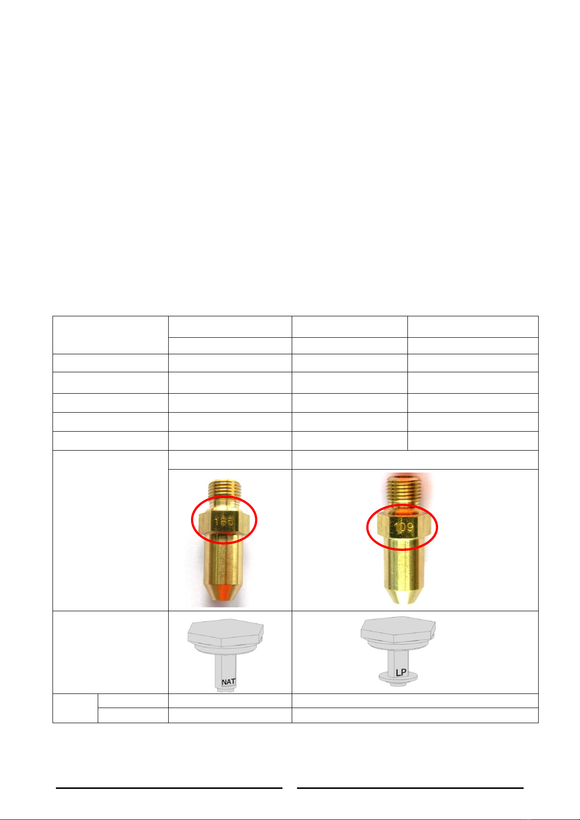
GAS SPECIFICATION TABLE
Natural Gas
Propane
ULPG
GE559-N
GE559-P
GE559-P
Single burner Heat
Input
16MJ/Hr
16 MJ/Hr
16 MJ/Hr
Heat Total
32 MJ/Hr
32 MJ/Hr
32 MJ/Hr
Burner Operating
1.0 kPa
2.75 kPa
2.75kPa
Supply Pressure
1.13 kPa
2.75 kPa
2.75 kPa
Gas Connection
¾” BSP Male
¾” BSP Male
¾” BSP Male
Burner Injector
Orifice#
#185
#109
Set-up of converter
Low
Flame
Size
Ø 0.65mm
Ø 0.65mm
Adjustment
Only if necessary
Only if necessary
CAUTION: Please replace the corresponding warning label that shows the gas
type operated when the qualified person will convert to another gas in order not
to cause death or injury or damage.

14
TROUBLESHOOTING
Consult the following table:
Problem
Cause
Remedy
Burners in the unit will
not turn “ON”
Main gas supply to unit is “OFF”
Ensure that the main gas supply to the unit is
“ON”
Not enough gas pressure.
Ensure that the gas line has enough gas
pressure. Ensure that the gas tanks are not
empty.
Clogged or blocked burner injector
orifice.
Call your authorized service agent.
Thermocouple connection to the
gas valve is loose or too tight.
Call your authorized service agent.
Faulty thermocouple.
Call your authorized service agent.
Faulty gas valve.
Call your authorized service agent.
Only one burner will not
turn “ON”
Clogged or blocked burner injector
orifice.
Call your authorized service agent.
Thermocouple connection to the
gas valve is loose or too tight.
Call your authorized service agent.
Faulty thermocouple.
Call your authorized service agent.
Faulty gas valve.
Call your authorized service agent.
Two burners produce
excessive carbon
deposits
Incorrect gas type supplied to unit.
Ensure that the gas type supplied to the unit
is correct based on the rating label. Refer to
the Gas Specification on Page 13.
Only one burner in a unit
produce excessive
carbon deposits.
Incorrect injector orifice installed.
Ensure that a correct injector orifice is
installed on the unit. Refer to Gas
Specification Table on Page 13 of this manual
Flame comes out from
the flue.
Incorrect gas type supplied to unit.
Ensure that the gas type supplied to the unit
is correct based on the rating label. Refer to
the Gas Specification on Page 13.
Incorrect injector orifice installed.
Ensure that a correct injector orifice is
installed on the unit. Refer to Gas
Specification Table on Page 13 of this manual
Flashback or backfire –
when the flame burns
near the injector and
with a sound like a blow
torch.
Crack on the burner ceramic.
Call your authorized service agent.
Replacement Parts
IMPORTA
N
T
:
Only
g
enu
i
n
e
authorized
rep
l
a
c
ement
p
art
s
should be used for the servicing and repair of
t
h
is
appl
ian
c
e
.
The instructions supplied with the parts should be followed when
rep
l
acing components.
For further information and servicing instructions, contact your nearest authorized service branch
.
When ordering replacement parts, please quote the part number and the description listing below. If the
part required is not listed below, request the part by description and quote model number and serial number
which is shown on the rating plate.
15
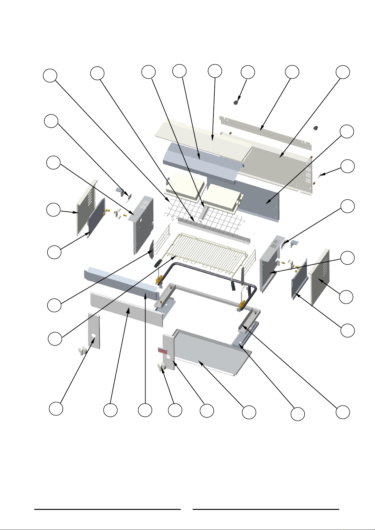
Explosion drawing
28
1
2
3
4
5
6
7
8
9
10
11
12
13
14
15
16
17
18
20
21
23
22
25
26
27
19
24

16
Explosion drawing(Continued)
29
30
31
32
33
34
35
36

17
Spare Parts List
NO.
DESCRIPTION
Part No
CODE
GE559-P
GE559-N
1
Rack
01.11.1062056
1
1
2
Rack support
01.02.1005371
2
2
3
Left insulation
01.15.1066413
1
1
4
Side panel-l
01.05.1029292
1
1
5
Left inner panel
01.15.1066420
1
1
6
Upper left plate
01.05.1029296
1
1
7
Burner protect
01.03.1015100
2
2
8
Upper inner2
01.15.1066419
1
1
9
Burner protect connector
01.05.1029298
1
1
10
Upper inner1
01.15.1066418
1
1
11
Top cover
01.05.1029295
1
1
12
Feet1
02.12.1165053
2
2
13
Back hold plate
01.15.1066412
1
1
14
Back panel
01.15.1066415
1
1
15
Back inner plate
01.15.1066417
1
1
16
Feet2
01.02.1005381
2
2
17
Upper right plate
01.05.1029297
1
1
18
Right inner panel
01.15.1066421
1
1
19
Right insulation plate
01.15.1066414
1
1
20
Side panel-l
01.05.1030294
1
1
21
Support assembly
01.09.1050453
1
1
22
Side bottom
01.05.1029291
2
2
23
Oil tray
01.05.1029290
1
1
24
Control panel-r
01.05.1030295
1
1
25
Knob
06.05.1472202
2
2
18
Spare Parts List
NO.
DESCRIPTION
Part No
CODE
GE559-P
GE559-N
26
Front insulation
01.15.1066416
1
1
27
Front cover
01.05.1029294
1
1
28
Control panel-l
01.05.1029293
1
1
29
Main pipe assembly
06.05.1472745
2
2
30
L-connector
01.18.1067451
2
2
31
Main burner injector/Orifice
(for Natural Gas) - #185
01.20.1068670
2
Main burner injector/Orifice
(for LPG) - #109
01.20.1068671
2
32
Infrared burner
01.03.1015139
2
2
33
Safety Gas Valve
01.20.1068572
2
2
34
Thermocouple
03.11.1250034
2
2
35
Manifold assembly
01.24.1070916
1
1
36
Regulator
01.22.1069526
1
1

15 Badgally Road, Campbelltown
NSW 2560
Thor after sales/service: 1300 225 960
V1.Rev4 12-20
This manual suits for next models
1
Table of contents
Other THOR Grill manuals


Popular Grill manuals by other brands


Weber
Weber SMOKEY JOE PREMIUM owner's guide

Nexgrill
Nexgrill 820-0015 manual

Lotus
Lotus CWK-74ET Instructions for installation and use

all-clad
all-clad PG715850 owner's guide

George Foreman
George Foreman RPGV3801BK SERIES use and care manual

Lang
Lang PB-24 Installation, operation, concept training, maintenance, & troubleshooting