THORAIR AM190001 User manual

L G R D E H U M I D I F I E R S
A M 1 9 0 0 0 1
A M 1 9 0 0 0 2

insulation, and con- tents, and maintain a healthy level of humidity. Using the LGR2200 may also prevent
secondary damage caused by high humidity.
WARNINGS
•Always store, transport, and use the unit in a horizontal position. If the unit is ever placed in a
vertical position, return it to the horizontal position and let it stand for at least 30 minutes before
turning it on.
•Do not move or carry the Dehumidifier while it is operating. When the Dehumidifier is operating,
the powerful airflow can cause unpredictable movement.
•NEVER allow children to play with or around the Dehumidifier.
•Do not alter or modify your Dehumidifier in any way. Use only authorized replacement parts .
Modifications or use of unauthorized parts could create a hazard and will void your warranty.
•Insert three prong-plug on power cord into a matching electrically grounded outlet. Do not use
adapter. Never cut off third prong.
•The Dehumidifier should never be operated near water as it will create a risk of serious injury from
electrical shock.
•Handle unit with care to avoid causing damage or injury.
•The Dehumidifier should always be operated on a flat surface. Do not operate where unit could fall,
or on slippery surfaces, as this could increase the chance of injury, fire, or electrical shock.
•Do not use the Dehumidifier near combustible gas, or hot air as unit could melt and cause a fire or
electrical hazard.
•Do not take the Dehumidifier apart or repair it unless you are qualified to do so. Never repair or
service unit while Dehumidifier is plugged in.
•Make sure the air intake and outlet are free from all materials and away from obstructions, as any
restrictions may cause the Dehumidifier to overheat and cause a shock or fire hazard.
•Unplug the Dehumidifier before performing any service or changing filters
•Do not stack more than 2 units high in order to avoid a tipping hazard – falling equipment can
cause bodily harm.
•Keep away from open flames and heat sources.
•Do not use or store where vapors from gasoline, sol- vents, thinners or other flammable materials
may be present.
POSITONING LGR2200/2500

For best results, operate your dehumidifiers in an enclosed area. Close all doors and windows that open
to the outside to maximize water removal efficiency. Place your dehumidifier away from obstructions,
and keep it away from anything that could block airflow into and out of the unit.
SET DRAIN HOSE
The LGR2200/2500 condensate pump connects to a plastic drainage hose. This hose is equipped with a
quick- connect fitting for quick attachment to the provided 25 ft. (7.5 m) drain hose. Unwrap the entire
hose and place the unattached end in a sink, drain, bucket or outdoors – anywhere that water can drain
out safely. If you use a bucket or other container for water collection, check it regularly to prevent
overflows.
NOTICE: Uncoil and straighten the entire drain hose. Do not leave any part of the hose coiled and do not
place the end of the hose higher than 20 ft. (6 m) above the bottom of the unit. Also check for kinks or
other obstructions that might restrict the flow of water. Obstructions may cause a water backup and
result in overflows.
PLUG THE UNIT
The LGR2200/2500 should be plugged into a 125volt outlet rated for at least 10 amps. Always plug the
cord firmly into the unit first, and then plug the other end into a suitable outlet.
Startup display and normal display modes
When unit is first plugged in to AC power, the control panel display will briefly cycle through a series of
readouts. This is part of the unit’s self-diagnosis procedure and no user intervention is required.
CONTROL PANEL
ON/OFF
Press and release to turn unit on or off.
MENU
Press to select next item in menu. Menu item will show in display.

SET
Press to toggle or select values in menu displayed
PUMP
Press and release to start purge.
IN
Shows Temp & humidity of the inlet
OUT
Shows Temp & humidity of the outlet
Cool
Shows Temp @ condenser
COMP A
Shows Current of the compressor
Runtime
Shows Job hours & life hours
STATE
Shows the state of the dehumidifier
HUMIDISTAT SETTING
The default operating mode keeps the dehumidifier running at its maximum capacity. This is ideal for
most restoration application. To control humidity at a specific level, described below:
1) Press MENU once, and screen shows as FIG A, Press SET until the screen shows as FIG B, an arrow
point the Moisture,
FIG A
FIG B
2) Press SET to adjust the target Moisture, Each press of the button increases the setting by 5%
increments, cycling through 90%RH and starting again at 40%RH.
3) Press MENU until the screen back to the main Menu.
TEMPERATURE SETTING
To change unit of temperature, described below:
1) Press MENU only once, and screen shows as FIG C, Press SET until the screen shows as FIG D, an
arrow point the Moisture,
2) Press SET to select Fahrenheit or Centigrade scale

FIG C
FIG D
AFTER THE JOB
To reduce the possibility of drips when moving the unit, follow these additional steps to ensure that all
water is removed from the unit.
NOTICE: To ensure the condensate tank empties completely while purging, make sure the unit is
positioned horizontally on a flat surface.
1) Gently rock the machine to ensure any water remaining on interior surfaces falls into the sump
area.
2) Press the PUMP key. When the purge cycle is complete, turn the unit off.
3) Remove the external drain hose, drain it carefully, coil it and secure it with one of the Velcro
straps provided on the side of the unit.
4) Unplug power cord from power supply and from base of the machine, coil neatly, coil it and
secure it with one of the Velcro straps provided on the side of the unit.
TRANSPORTATION AND STORAGE
NOTICE: Handle the unit carefully. Do not drop, throw, or place the unit where it could fall. Rough
treatment can damage this equipment and may create a hazardous condition or void warranty.
•Do not expose the control panel to moisture, snow or rain.
•Protect from freezing.
•Store and transport securely to avoid any damaging impact to internal parts.
•Secure during transport to prevent sliding and possible injury to vehicle occupants.
MAINTENANCE SCHEDULE
WARNING! ELECTRIC SHOCK HAZARD. Unplug unit before cleaning or servicing.
WARNING: Risk of dust and contaminants exposure. Use of respirator mask and gloves is recommended.
If unit has been exposed to potentially dangerous contaminant, clean thoroughly and sanitize before
reuse.

NOTICE: The unit is fitted with sensitive electronic sensors. Protect the sensors and their lead wires from
damage and do not expose them to water or cleaning solution.
Before each use Inspect the electrical cord for damage. Look for fraying, cuts, etc. Replace the cord if
you find any damage.
Inspect, vacuum or replace filter. The LGR2200/2500 is provided with a 3M™ HAF High Air Flow .HAF
filters may be vacuumed clean and reused up to three times before replacement. Use a HEPA vacuum
and brush tool to remove any dust or de- bris. Do not use compressed air or expose the filter to any
liquids, as may damage the filter.
Monthly Inspect coils. Clean when dust accumulation is visible. In normal use, dust can accumulate and
can restrict airflow, reducing performance and causing the unit to overheat. Use a vacuum cleaner with
a brush tool and a soft cloth to remove any debris. Take care not to damage any interior components.
To maintain appearance, wipe interior and exterior surfaces with a damp cloth. For deep cleaning and a
lasting, protective shine, use an automotive interior cleaner.
Clean pump check valve and basin If the unit displays the message “STATE PUMP”, which means
the pump may be blocked, check valve and pump basin may need to be cleaned. Remove grills and cover.
Remove screws from pump base and lift out pump. Wipe out pump basin with a damp cloth. Inspect the
pump base for build-up of debris and clean if needed. Unthread barbed fitting with check valve and rinse
fitting and check valve with clean water. Reinstall check valve into barbed fitting and install the barbed
fitting into pump. Do not overtighten. Reinstall pump on base. Reinstall cover and grills.
Clean coils With the cover removed, inspect both coils. If excessive dust and debris is present, vacuum
thoroughly and/or clean with coil cleaner.
LGR2200/2500 SPECIFICATIONS
MODEL
LGR2200
LGR2500
Power Input
110 Volts, 60 Hz
110 Volts, 60 Hz
Compressor Power
3/4HP @Aham
1HP @Aham
Motor Rating:
1/3 hp
1/3hp
Current:
7 amps
7.5amps
Water Removal
125Pints/Day (71L) @ 90F/90%
80Pints/Day (45L) @ 80F/60%
135Pints/Day (71L) @ 90F/90%
85Pints/Day (45L) @ 80F/60%
CFM:
250-500
300-550CFM
Weight
36.5Kg
42Kg
Size
24x14x21inch
26*22*37inch
Certifications:
ETL
ETL
Specifications are subject to change without notice.

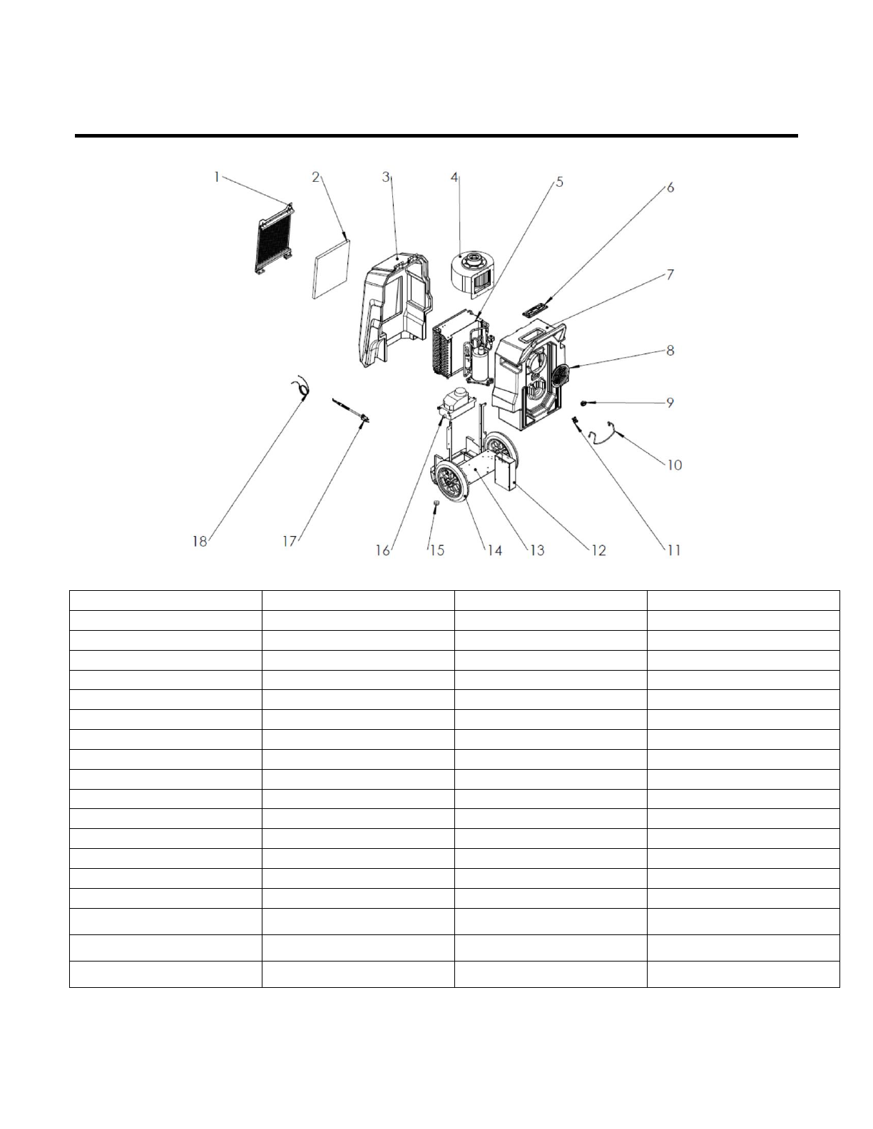
LGR2200/2500 PARTS LIST
Ref
Part Number
Description
Qty Req
1
LGR2201
Inlet Grill
1
2
LGR2202
3M HAF Filter
1
3
LGR2203
Water Pump
1
4
LGR2204
Condens
1
5
LGR2205
Airflow Guide
1
6
LGR2206
1/3 HP Motor
1
7
LGR2207
Motor Support
1
8
LGR2208
Motor Seal Panel
1
9
LGR2209
Switch Panel
1
10
LGR2210
Fan Inlet Cover
1
11
LGR2211
Outlet Grill
1
12
LGR2212
Fan
1
13
LGR2213
Control Box
1
14
LGR2214
Compressor Base
1
15
LGR2215
Down Housing
1
16
LGR2216
Up Housing
1
16
LGR2217
Quick Pipe connector
1
17
LGR2218
Handle
2
LGR2500 PARTS LIST
Ref
Part Number
Description
Qty Req
1
LGR2501
Inlet Grill
1
2
LGR2502
Filter
1
3
LGR2503
Inlet Housing
1
4
LGR2504
Fan Motor
1
5
LGR2505
Compressor
1
6
LGR2506
Control Panel
1
7
LGR2507
Outlet Housing
1
8
LGR2508
Outlet Grill
1
9
LGR2509
Cord Connector
1
10
LGR2510
Bracket
1
11
LGR2511
Water Connector
1
12
LGR2512
Control Box
1
13
LGR2513
Base
1
14
LGR2514
Wheel
2
15
LGR2515
Rubber
2
16
LGR2516
Pump
1
16
LGR2517
Cord
1
17
LGR2518
Drain Hose
1

SYSTEM MESSAGES
The LGR2200/2500 control system constantly monitors internal operating conditions. If the system detects a
problem, it will state the ERROR code at the after the STATE row, instead RUN/OFF. If the display
shows an ER message, first unplug the unit and then plug it back in. This will usually reset the electronics,
and the unit will begin operating normally. If the error message reappears, refer to the explanation and
solution shown below.
C O N T R O L P A N E L
M E S S A G E
E X P L A N A T I O N A N D S O L U T I O N
STATE:COMP
Compressor may do not work, Check compressor cable for proper connection , if
contact service center
STATE: MOIS
Check inlet Temp/RH sensor for proper connection. If error persists, contact service.
STATE: TEMP 1
Check inlet Temp/RH sensor for proper connection. If error persists, contact service.
STATE: TEMP 2
Check outlet Temp/RH sensor for proper connection. If error persists, contact service.
STATE: PUMP
Check for obstructions in drain hose. If clogged, remove hose from unit and blow hose
out with compressed air. Inspect and clean the pump check valve and pump basin.
TROUBLE SHOOTING
Water drips out
when moving unit
Unit was unplugged before
purging was complete.
Purge unit before moving. See “At the End of the
Job,” p. 4.
Unit does not
operate
Unit not switched on.
No power to machine.
Switch unit on.
Plug in unit; check power cord connection at wall
outlet and at base of unit.
Unit operating, but
room not dry
Not enough time to dry. Poor
air movement in room.
Excessive moist air infiltration.
Allow more time for drying.
Increase air movement with air movers. Seal off area
to reduce infiltration.
Unit collects too
little water
Room air is dry.
Room temperature is too low.
Filter is clogged.
Coils are clogged.
Confirm humidity level with hygrometer. Increase
room temperature.
Check filter. Clean or replace as necessary. Check
coils. Clean as necessary.
Unit stop working
after few hours
The setted humidity is less than
the environment humidity
Decrease the setted humidity according to the
HUMIDISTAT SETTING process
Thank you for purchasing this product. Please read the instructions carefully and follow all warnings.
All products are manufactured to be easy to use and provide years of worry free service when the
recommendations in this manual are followed.
This manual suits for next models
3
Table of contents


