THORENS PC 650 User manual
THORENS
SERVICE
STEREO
CASSETTE
DECK
3
HEAD
STEREO
CASSETTE
“PHONES
Printed
in
Germany
-
650—1179—1
IMPORTANT
CAUTION
NOTICE:
The
service
procedures
described
are
intended
for
the
information
of
QUALIFIED
ELECTRONIC
SERVICE
TECHNICIANS.
Exposure
to
Hazardous
Voltages
may
be
involved
in
some
of
the
service
procedures
described.
The
unit
under
repair
should
be
disconnected
from
the
Line
Voltage
before
proceeding
with
any
service
adjustments
involved
that
require
the
cabinet
to
be
removed.
All
servicing
requiring
the
removal
of
the
cabinet
should
be
referred
to
QUALIFIED
SERVICE
PERSONNEL.
The
representative
serving
your
area
and
THORENS
disclaim
any
responsibility
for
personal
injury
or
damage
for
failure
to
observe
this
warning.
ACHTUNG!
Vor
dem
Offnen
des
Gerates
Netzstecker
ziehen!

THORENS
PC
650
SERVICE
MANUAL
Contents
Page
PRELIMINARY
PROCEDURES
1
TAPE
TRANSPORT
MECHANISM
2
ERASE
AND
RECORD/PLAYBACK
HEADS
3
RECORD/PLAY
BACK
ELECTRONICS
4
TRANSPORT
FUNCTIONS
6
Parts
List
Diagrams

THORENS
PC
650
SERVICEANLEITUNG
Inhalt
VORBEREITUNG
ZUM
SERVICE
BANDLAUFMECHANIK
LOSCH-
UND
TONKOPFE
AUFNAHME-WIEDERGABE-ELEKTRONIK
LAUFFUNKTIONEN
Ersatzteilliste
Diagramme
Seite
11
12
13
14
16

PRELIMINARY
PROCEDURES
1.
Preparation
for
Servicing
The
mechanical
and
electrical
components
of
the
cassette
deck
are
made
accessible
for
servicing
by
removing
the
cabi-
net
and
the
front
panel
assembly
according
to
the
following
procedures.
Note:
the
azimuth
adjustment
(Section
9)
can
also
be
per-
formed
without
disassembling
the
unit.
Removal
of
the
Cabinet
a)
Remove
the
three
Phillips
head
screws
in
the
recess
in
the
rear
side
of
the
unit
(Fig.
1).
b)
Holding
the
front
panel,
pull
the
cabinet
away
toward
the
rear.
Removal
of
the
Cassette
Compartment
Front
c)
Loosen
the
two
screws
on
the
cover
front
of
the
cassette
compartment
and
remove
the
front
(Fig.
2).
Removal
of
the
Front
Panel
Assembly
d)Remove
the
twelve
Phillips
head
screws
(8053164)
above
and
below
on
the
front
panel
(Fig.
3).
e)
Pull
off
the
knobs
and
remove
the
front
panel
with
the
timer
blocking
knob
(3063085),
the
power
switch
pres-
sure
spring
(3061915),
and
blocking
piece
(3063075).
Cassette
Compartment
f)
Remove
the
mantel
assembly
(Fig.
4).
g)
Pull
off
the
clamp
connector
on
the
orange
wire
of
the
leaf
contact
assembly
3062295
(cassette
compartment
button)
from
the
spade
pin
on
board
VM
1
so
that
the
function
selector
buttons
remain
in
operation.
Insulate
the
clamp
connector.

TAPE
TRANSPORT
MECHANISM
2.
Fast
Forward
and
Reverse
Functions
lf
either
the
fast
forward
or
reverse
function
does
not
en-
gage,
check
first
whether
the
rocker
assembly
(Fig.
5)
is
moving
freely.
The
rocker
must
fall
from
its
own
weight
when
the
cassette
deck
is
placed
on
its
side.
If
binding
occurs,
slightly
alter
the
positions
of
the
clip
washers
(four
arrows).
If
the
reel
motor
does
not
start,
refer
to
Section
3.
3.
Reel
Motor:
Drive
Voltage
Test
and
Replacement
le
a)
Unsolder
the
connecting
wires
at
the
reel
motor
(wires
St
06,
St
07).
b)
Solder
a
100
Ohm,
1/2
Watt
resistor
to
the
connecting
wires.
Avoid
chassis
contact!
c)
Depress
and
hold
down
either
the
fast
forward
or
re-
verse
button.
d)
If
the
voltage
measured
on
the
resistor
is
less
than
4.5
VDC,
check
the
performance
of
the
Logic
Control
Board
VM
17
and
the
Power
Control
Board
VM
14
with
reference
to
the
TRANSPORT
FUNCTIONS
description
(Sections
16
and
17).
e)
If
the
voltage
is
at
least
4.5
VDC
and
the
reel
motor
does
not
start,
it
must
be
replaced
according
to
the
following
procedure.
3191415
F
f)
Remove
the
two
cylinder-head
screws
“A”
(Fig.
6)
and
the
two
separators
(3019445)
between
the
rear
of
the
mounting
plate
and
the
reel
drive
aggregate.
g)
Carefully
guide
out
the
reel
drive
aggregate
toward
the
rear.
Avoid
damaging
the
gears.
h)
Demount
the
motor
(3119705)
from
the
reel
drive
aggre-
gate
by
removing
the
two
Phillips
head
screws.
i)
Screw
on
the
replacement
motor.
A
play
of
0,1
mm
is
necessary
between
the
motor
pinion
“C”
and
the
trans-
mission
gear
B”’.
j)
Check
the
free
movement
of
the
rocker
assembly
accord-
ing
to
Section
2.
k)
Carefully
return
the
reel
drive
aggregate
into
its
mounting
position.
The
stop
pin
D’
on
the
aggregate
must
pass
between
the
adjustment
lugs
E”
on
the
mounting
plate.
1)
Mount
the
aggregate
with
the
two
screws
‘A’,
tightening
evenly.
m)Check
the
free
movement
of
the
rocker
assembly
once
again
by
turning
the
pinion
C”
in
alternate
directions.
n)
Solder
the
colored
wire
(St
06)
to
+”
and
the
black/
white
wire
(St
07)
to
the
other
terminal
of
the
motor.
o)
Check
the
height
of
the
head
bracket
(Section
4),
the
tape
tension
(Section
5),
and
the
tape
speed
(Section
6),
adjusting
as
necessary.
Fig.
5
3119705
4.
Head
Bracket
Height
Adjustment
The
height
of
the
head
bracket
influences
the
contact
force
between
the
record/playback
head
and
the
tape.
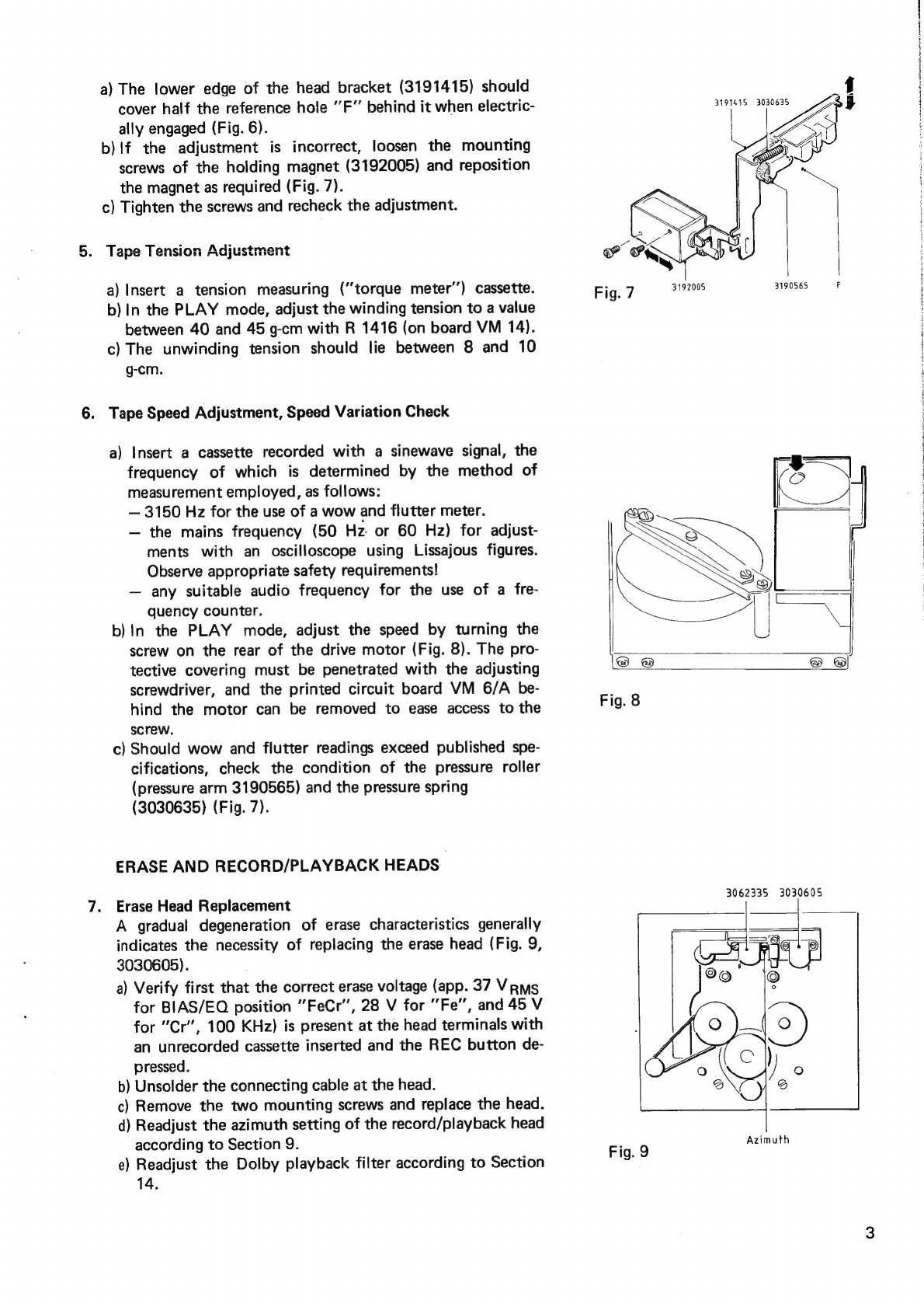
a)
The
lower
edge
of
the
head
bracket
(3191415)
should
cover
half
the
reference
hole
‘’F”
behind
it
when
electric-
ally
engaged
(Fig.
6).
b)!f
the
adjustment
is
incorrect,
loosen
the
mounting
screws
of
the
holding
magnet
(3192005)
and
reposition
the
magnet
as
required
(Fig.
7).
c)
Tighten
the
screws
and
recheck
the
adjustment.
.
Tape
Tension
Adjustment
a)
Insert
a
tension
measuring
(“torque
meter’’)
cassette.
b)
In
the
PLAY
mode,
adjust
the
winding
tension
to
a
value
between
40
and
45
g-cm
with
R
1416
(on
board
VM
14).
c)
The
unwinding
tension
should
lie
between
8
and
10
g-cm.
.
Tape
Speed
Adjustment,
Speed
Variation
Check
a)
Insert
a
cassette
recorded
with
a
sinewave
signal,
the
frequency
of
which
is
determined
by
the
method
of
measurement
employed,
as
follows:
—
3150
Hz
for
the
use
of
a
wow
and
flutter
meter.
—
the
mains
frequency
(50
Hz
or
60
Hz)
for
adjust-
ments
with
an
oscilloscope
using
Lissajous
figures.
Observe
appropriate
safety
requirements!
—
any
suitable
audio
frequency
for
the
use
of
a
fre-
quency
counter.
b)
In
the
PLAY
mode,
adjust
the
speed
by
turning
the
screw
on
the
rear
of
the
drive
motor
(Fig.
8).
The
pro-
tective
covering
must
be
penetrated
with
the
adjusting
screwdriver,
and
the
printed
circuit
board
VM
6/A
be-
hind
the
motor
can
be
removed
to
ease
access
to
the
screw.
c}
Should
wow
and
flutter
readings
exceed
published
spe-
cifications,
check
the
condition
of
the
pressure
roller
(pressure
arm
3190565)
and
the
pressure
spring
(3030635)
(Fig.
7).
ERASE
AND
RECORD/PLAYBACK
HEADS
Erase
Head
Replacement
A
gradual
degeneration
of
erase
characteristics
generally
indicates
the
necessity
of
replacing
the
erase
head
(Fig.
9,
3030605).
a)
Verify
first
that
the
correct
erase
voltage
(app.
37
Vrms
for
BIAS/EQ
position
"FeCr”,
28
V
for
Fe”,
and
45
V
for
"Cr’,
100
KHz)
is
present
at
the
head
terminals
with
an
unrecorded
cassette
inserted
and
the
REC
button
de-
pressed.
b)
Unsolder
the
connecting
cable
at
the
head.
c)
Remove
the
two
mounting
screws
and
replace
the
head.
d)
Readjust
the
azimuth
setting
of
the
record/playback
head
according
to
Section
9.
e)
Readjust
the
Dolby
playback
filter
according
to
Section
14.
Fig
7
3192005 3190565
F
3062335
3030605
Azimuth
Fig.
9

8.
10.
Record/Playback
Head
Replacement
Should
a
loss
of
high-frequency
signals
be
noted
in
the
reproduced
program,
the
calibration
and
test
pro-
cedures
of
Sections
9,
10
and
13
should
first
be
conducted.
!f
specified
performance
cannot
be
attained,
replace
the
record/playback
head
(3062335,
Fig.
9)
as
follows:
a)
Unsolder
the
shielded
cables
from
the
terminal
board
of
the
head.
b)
Remove
the
left-hand
mounting
screw
and
loosen
the
right-hand
screw.
c)
Remove
the
head
and
mount
a
replacement
head.
The
left-hand
screw
is
to
be
tightened
completely,
while
the
right-hand
screw
should
be
turned
until
the
head
is
paralle!
to
the
mounting
plate
(chassis).
d)
Solder
the
shielded
cabies
onto
the
terminal
board
of
the
head.
e)
Perform
the
adjustments
in
Sections
9
and
11
-
13.
Azimuth
Adjustment
The
azimuth
(head
alignment)
adjustment
can
be
performed
without
removing
the
front
panel
assembly
through
the
access
hole
above
the
cassette
compartment.
a)
Demagnetize
the
erase
and
record/playback
heads.
b)
Insert
an
azimuth-adjustment
cassette,
or
a
cassette
recorded
with
a
10
KHz
sinewave
signal,
and
connect
a
dual-channel
oscilloscope
(in
chopping
mode)
to
the
outputs
L
and
R.
c)
In
the
PLAY
mode,
turn
the
right-hand
mounting
screw
of
the
record/playback
head
(Fig.
9)
to
achieve
the
maximum
output
voltage
and
the
identical
phase
in
both
channels.
Avoid
secondary
volt-
age
maxima!
RECORD/PLAYBACK
ELECTRONICS
Before
checking
the
performance
of
the
record/playback
system,
verify
the
correct
head
bracket
height
according
to
Section
4.
Demagnetize
the
heads
and
clean
with
alcohol.
The
tests
and
calibration
procedures
are
to
be
carried
out
in
the
order
presented.
Measurement
points
MP
1
-
MP
4
are
located
on
circuit
board
VM
1.
The
location
of
other
measurement
points
and
electronic
components
is
given
by
the
first
or
the
first
two
identifying
numerals;
thus,
R
1513
is
located
on
board
VM
15,
etc.
All
voltage
specifications
are
referred
to
0
V.
Performance
Check
of
the
Record/Playback
Electronics
a)
Switch
in
the
ultrasonic
filter
(20
Hz
-
20
KHz:
linear)
of
the
audio
millivoltmeter
intended
for
the
measurements.
b)
Feed
in
a
333
Hz
sinewave
signal
and
set
the
voltage
level
at
MP
1
(L)
and
MP
2
(R)
to
-30
dBm
(app.
25
mV)
with
the
signal
generator
or
the
INPUT
level
controls.
—
The
voltage
amplification
of
the
Dolby
record
board
VM
6/A
is
approximately
29
dB,
so
that
a
signal
level
of
about
1
mV
should
be
measured
at
points
S
612
(L)
and
S
603
(R).
~
The
voltage
leveis
at
MP
1
and
MP
2
and
at
S
614
(L)
and
S
605
(R)
should
be
approximately
the
same.
c)
Check
the
BIAS/EQ
switching
at
board
VM
8:
Voltage
Level
at:
S
808
(L)
/
S
806
(R)
$
811
(L)
/S
802
(R)
for:
FeCr
app.
4.5
mV
50
mV
Fe
5.0
mV
55
mV
Cr
8.5
mV
95
mV
d)
Insert
an
unrecorded
cassette,
set
the
BIAS/EQ
selector
to
the
appropriate
position,
and
press
the
REC
and
PLAY
buttons
simultaneously.
Switch
off
the
filter
at
the
millivoltmeter
and
measure
the
100
KHz
voltage
at
VM
10:
S
1004
(Bias
Voltage)
S
1003
(Erase
Voltage)
for:
FeCr
47
Vrms
37
Vos
‘
Fe
33
Vams
28
Vrms
Cr
57
Vrams
45
Veams
Switch
in
the
filter
at
the
millivoltmeter
for
the
remaining
measurements
below.

11.
12.
13.
e)
The
voltage
at
MP
3
(L)
and
MP
4
(R)
should
lie
at
approximately
25
mV.
Should
deviations
be
regis-
tered,
see
Section
11.
—
The
voltage
amplification
of
the
Dolby
playback
board
VM
6/W
is
approximately
29
dB,
so
that
a
signal
level
of
about
1
mV
should
be
measured
at
points
S
612
(L)
and
S
603
(R).
—
The
frequency
response
should
remain
linear
when
the
signal
frequency
is
varied
within
the
range
specified
in
the
instruction
manual.
If
deviations
from
published
data
are
registered,
perform
the
adjustment
procedures
in
Sections
9
and
11
-
13.
f)
The
voltage
level
at
the
output
(DIN
3
and
5,
LINE
OUT
L
and
R)
should
lie
at
approximately
20
mV,
Measure
the
frequency
response
as
a
final
check.
Playback
Level
Calibration
a)
Insert
a
level
calibration
cassette
recorded
with
333
Hz
(250
nW/m).
b)
In
the
PLAY
mode,
adjust
R
228
(L)
and
227
(R)
to
achieve
a
voltage
level
of
740
mV
at
MP
3
(L)
and
MP
4
(R).
Signal
Level
Meter
Calibration;
Limiter
Check
and
LED
Threshold
Adjustment
a)
Insert
an
unrecorded
cassette,
turn
the
LIMITER
switch
to
OFF,
and
press
REC
button.
b)
Feed
a
1KHz
sinewave
signal
into
the
DIN
L
and
R
inputs.
c)
Set
the
voltage
level
at
MP
1
(L)
and
MP
2
(R)
to
580
mV
with
the
signal
generator
or
the
INPUT
level
controls.
d)
Adjust
R
117
(L)
and
R
118
(R)
to
bring
the
meter
indication
to
0
dB”
(beginning
of
the
red
range).
e)
Raise
the
input
voltage
level
by
approximately
5
dB.
f)
When
the
LIMITER
switch
is
now
turned
to
ON,
the
meter
indication
must
fall
to
between
“0
dB”
and
’’+1.5
dB”,
and
the
LED’s
must
illuminate.
g)
Adjust
the
LED
switching
threshold
with
a
voltage
level
of
600
mV
at
MP
1
and
MP
2.
Set
R
1603
(L)
and
R
1604
(R)
so
that
LED’s
just
begin
to
illuminate.
Frequency
Response
Calibration,
TEST
Generator
Adjustment
The
following
procedure
should
be
performed
in
its
entirety,
in
the
order
presented,
even
if
deficiencies
in
the
frequency
response
appear
for
only
certain
varieties
of
tape.
a)
Center
the
settings
of
both
Dolby
CAL
controls
on
the
front
panel.
b)
Insert
an
unrecorded
CrO9
cassette
(DIN
C
401
R),
set
the
BIAS/EQ
selector
to
'’Cr”’,
and
press
the
REC
and
PLAY
buttons
simultaneously.
c)
Feed
in
a
333
Hz
sinewave
signal
and
set
the
voltage
level
at
MP
1
(L)
and
MP
2
(R)
to
-30
dBm
(app.
25
mV)
with
the
signal
generator
or
the
INPUT
level
controls.
This
level
is
to
be
retained
for
the
entire
calibration
procedure.
d)
Switch
the
signal
generator
frequency
to
14
KHz.
Adjust
the
signal
level
to
-30
dBm
at
MP
3
(L)
and
MP
4
(R)
with
R
111
(L)
and
R
112
(R).
e)
Switch
back
to
333
Hz.
Adjust
the
signal
level
to
-30
dBm
at
MP
3
(L)
and
MP
4
(R)
with
R
107
(L)
and
R
108
(R).
f)
Repeat
steps
d
and
e
to
eliminate
level
differences
between
333
Hz
and
14
KHz
and
thereby
achieve
a
linear
frequency
response.
If
the
frequency
characteristic
at
high
frequencies
is
not
sufficiently
linear,
check
the
condition
of
the
record/playback
head
(3062335,
Fig.
9)
and
replace,
if
necessary,
according
to
Section
8.
g)
Depress
the
TEST
button
and
adjust
R
1513
(TEST
generator
level)
to
bring
the
signal
level
meter
in-
dication
to
0
dB”
(beginning
of
the
red
range).
h)
Insert
an
unrecorded
Fe
cassette
(Maxell
UDXL
1),
set
the
BIAS/EQ
selector
to
Fe’,
and
press
the
REC
and
PLAY
buttons
simultaneously.
i)
Adjust
R
1001
to
eliminate
level
differences
between
333
Hz
and
14
KHz
at
MP
3
and
MP
4.
Discrep-
ancies
in
level
which
may
be
observed
between
the
channels
should
be
averaged
out.
j)
Recheck
the
function
of
the
TEST
generator.
When
the
TEST
button
is
depressed,
the
"0
dB”
indi-
cation
must
approximately
be
achieved
once
again.
k)
Insert
an
unrecorded
FeCr
cassette
(Sony),
set
the
BIAS/EQ
selector
to
‘FeCr’’,
and
press
the
REC
and
PLAY
buttons
simultaneously.
|)
Adjust
R
184
to
eliminate
level
differences
between
333
Hz
and
15
KHz
at
MP
3
and
MP
4.
Discrep-
ancies
in
level
which
may
be
observed
between
the
channels
should
be
averaged
out.
m)
Recheck
the
function
of
the
TEST
generator
as
described
in
step
j.

14.
Calibration
of
the
Dolby
Playback
Filter
15.
The
Dolby
playback
filter
generally
requires
recalibration
only
after
repairs
on
the
boards
VM
6/A
or
VM
10
have
been
carried
out
or
the
erase
head
has
been
replaced.
a)
Insert
an
unrecorded
cassette,
set
the
BIAS/EO
selector
to
the
appropriate
position,
turn
the
Dolby
switch
to
ON,
and
press
the
REC
and
PLAY
buttons
simultaneously.
b)
Feed
in
a
2
KHz
sinewave
signal;
set
the
leve!
for
an
indication
of
about
’’-10
dB”
on
the
signal
level
meters.
c)
Adjust
L
604
(L)
and
L
603
(R)
on
the
Dolby
playback
board
VM
6/W
for
the
minimum
voltage
at
MP
3
(L)
and
MP
4
(R).
d)
The
difference
in
voltage
level
between
Dolby
ON
and
OFF
must
be
less
than
1
dB,
measured
at
MP
3
and
MP
4.
Calibration
of
the
Dolby
Record
Filter
The
Dolby
record
filter
generally
requires
recalibration
only
after
repairs
on
the
board
VM
6/W
have
been
carried
out.
a)
Insert
an
unrecorded
cassette
and
press
the
REC
button.
b)
Feed
in
a
333
Hz
sinewave
signal;
set
the
level
for
a
visible
indication
(about
’-20
dB’’)
on
the
signal
level
meters.
c)
Switch
the
signal
generator
frequency
to
19
KHz,
retaining
the
same
signal
level.
d)
Adjust
L
604
(L)
and
L
603
(R)
on
the
Dolby
record
board
VM
6/A
for
the
minimum
voltage
(de-
termined
with
an
oscilloscope)
at
MP
1
(L)
and
MP
2
(R).
TRANSPORT
FUNCTIONS
16.
The
control
commands,
which
determine
the
tape
transport
functions,
are
produced
on
the
Logic
Control
Board
VM
17
and
delivered
to
the
Power
Control
Board
VM
14
for
execution.
Logic
Control!
Board
VM
17
When
one
of
the
function
selector
buttons
is
pressed,
the
corresponding
logic
control
input
is
set
to
logical
0
(0
V)..The
reception
of
commands
can
be
verified
with
DC
voltage
measurements
on
the
input
connections
(connector
pins):
Connection
Function
Button
Pressed
Not
Pressed
S$
1701
STOP
OV
app.
+12
V
(1)
S
1702
RECORD
OV
app.
+12
V,0
V
w/PLAY
S
1704
PAUSE
OV
app.
+12
V
S$
1705
PLAY
OV
app.
+12
V
S
1706
F.
Rew.
Ov
app.
+12
V
S
1707
F.
Fwd.
OV
app.
+12
V
(1}:
If
S
1701
remains
at
O
V,
the
clamp
connector
on
the
orange
wire
of
the
cassette
compartment
contact
has
not
been
removed
from
the
pin
on
VM
1.
A
further
input
is
connection
S
1714,
which
receives
voltage
pulses
from
VM
14
whenever
the
reel
motor
is
running.
The
DC
voltage
value
on
S
1714
lies
between
+1
V
and
+3
V
when
the
tape
is
in
motion.
An
input
command
0
causes
the
logic
circuit
to
produce
a
control
command
of
logical
71
at
the
appro-
priate
output
connection.
Connection
Function
Function
ON
Function
OFF
S
1716
RECORD
app.
+12
V
app.
OV
$1717
PLAY
app.
+12
V
app.
OV
S$
1719
F.
Fwd.
app.
+12
V
app.
0
V
S
1720
F.
Rwd.
app.
+12
V
app.
OV
When
the
function
STOP
has
been
initiated,
all
commands
of
logical
1
(+12
V)
are
absent.
If
the
voltage
pulses
at
S
1714
disappear,
a
control
command
0
is
produced
at
connection
S
1718
to
cause
the
holding
magnet
to
be
released
by
VM
14
during
operation
in
the
PLAY
mode.

Logic
Elements
The
logic
circuit
employs
double
NAND
gates,
the
inputs
E14
of
which
are
connected
to
the
buttons
in
the
control
array.
The
terminal
A
is
the
output
of
each
gate
combination.
The
input
E2
is
connected
to
the
second,
internal
output.
The
logical
relationships
for
each
individual
NAND
gate
may
be
expressed
as
follows:
A=
1
when
E,
=0,
Eg
=0,
or
Ey
=
EQ
=
0
A=Owhen
Ej
=E9=1
Thus,
if
the
input
E4
of
the
double
combination
is
set
to
0
(input
command),
then
A=1
and
therefore
E9
=
0
(from
the
upper
NAND
gate).
Eo
As
soon
as
Eg
=
0,
A
is
held
to
1
even
after
the
button
is
released
and
E
7
reverts
to
1
(latching
action).
Ey
An
input
command
0
thus
causes
the
corresponding
command
bus
(designated
in
the
circuit
diagram
with
STOP,
Vorl.,
PLAY,
RECORD,
Riickl.,
and
PAUSE)
connected
to
the
output
A
to
be
set
to
1.
At
the
same
time,
the
input
command
0
sets
the
functions
which
are
to
be
canceled
to
0
through
a
diode
array.
The
Production
of
Control
Commands
STOP
PAUSE
RECORD
When
the
button
contact
S
101
is
closed,
the
NAND
gate
output
IC
1704
(10)
is
set
to
1.
Because
of
the
latching
action,
this
state
is
maintained
even
after
S
101
is
released
and
IC
1704
(8)
returns
to
1
through
R
1721.
Closing
the
contact
sets
all
other
command
buses
to
0
through
D
1709,
D
1715,
D
1720,
D
1731,
and
D
1736.
In
contrast
to
the
other
(run’’)
functions,
the
state
1
at
iC
1704
(10)
does
not
constitute
a
command.
Rather,
the
absence
of
all
other
commands
causes
the
tape
to
be
stopped,
as
described
below
under
’’Tape
Transport
Stop”.
Operation
proceeds
in
the
same
manner
as
STOP
when
the
contact
S
104
is
closed;
however,
the
RECORD
bus
is
not
set
to
0.
Connection
S
1709
is
fed
from
+12
V
through
R
196
(VM
1)
for
all
transport
functions
except
PLAY,
bringing
T
1702
into
conduction.
Closing
contact
S
102
causes
approximately
0
V
to
apear
at
the
collector
of
T
1702.
As
a
result,
D
1710
and
D
1732
conduct,
cancelling
the
Fast
Forward
and
Rewind
functions.
D
1753.
conducts,
turning
T
1705
off.
Because
of
the
latching
action,
IC
1703
(4)
and
thus
the
RECORD
output
S
1716
are
set
and
held
to
RECORD
command
1.
As
soon
as
the
RECORD
button
is
released,
T
1705
conducts
because
of
the
positive
voltage
(command
1)
at
S
1716.
The
emitter
of
T
1705
is
thereby
pulled
toward
+12
V.
This
voltage
prevents
IC
1702
(6)
from
being
set
to
0
when
the
PLAY
contact
is
closed
(over
the
relatively
high
impedance
R
1748).
The
re-
cording
function
can
be
initiated
only
when
S
102
and
S
105
are
closed
simul-
taneously,
since
T
1705
will
be
turned
off
at
that
moment.
A
O
appears
immed-
iately
at
IC
1702
(5)
,
so
that
subsequent
conduction
of
T
1705
is
of
no
con-
sequence.
If
the
PLAY
function
has
already
been
initiated,
T
120
(VM
1)
conducts,
turning
T
1702
off.
Closing
the
RECORD
contact
has
no
effect
on
operation
in
this
case.
A
cassette
without
rear
breakout
lugs
will
not
close
the
recording
inhibit
contact.
In
this
manner,
transmission
of
a
RECORD
command
to
the
Power
Control
Board
via
S
1716
is
prevented
(VM
1).
St
i
a
a
a
PLAY
Fast
Forward
Fast
Rewind
Operation
proceeds
in
a
similar
manner
to
STOP
when
the
contact
S
105
is
closed
Since
switching
occurs
over
R
1748,
PLAY
cannot
be
activated
when
T
1705
has
been
brought
into
conduction
through
the
RECORD
function
(see
RECORD”).
The
PLAY
command
1
appears
at
connection
S
1717.
Operation
proceeds
in
a
similar
manner
to
STOP
when
the
contact
S
107
is
closed
The
Fast
Forward
command
1
appears
at
connection
S
1719.
Operation
proceeds
in
a
similar
manner
to
STOP
when
the
contact
S
106
is
closed
The
Fast
Rewind
command
1
appears
at
connection
S
1720.
If
the
MEMORY
button
is
engaged,
the
positive
voltage
on
S
1720
is
conducted
to
C
143
when
the
counter
position
000
is
reached,
thus
bringing
T
119
briefly
into
conduction
and
initiating
the
STOP
function.
Tape
Transport
Stop
The
motion
of
the
cassette
is
terminated
at
the
end
of
the
tape
or
through
a
Function
Indicators
STOP
or
PAUSE
command
by
the
Tape
Transport
Stop
circuitry.
During
normal
operation
in
the
PLAY
(or
RECORD)
mode
or
during
Fast
For-
ward
or
Rewind,
voltage
pulses
are
delivered
from
the
Power
Control
Board
VM
14
through
connection
S
1714
and
are
amplified
by
T
1707.
Rectification
and
voltage
doubling
is
then
performed
with
D
1751
and
D
1752.
The
resulting.
positive
voltage
on
the
cathode
of
D
1752
brings
T
1708
into
conduction,
turning
T
1709
off.
No
stopping
function
is
initiated.
At
the
end
of
the
tape,
the
reel
motor
stalls,
and
thus
the
voltage
pulses
disappear
on
S
1714.
T
1708
is
turned
off,
T
1709
turned
on.
The
collector
voltage
of
T
1709
consequently
falls
to
nearly
O
V,
extinguishing
a
Fast
Forward
command
1
on
connection
S
1719
through
D
1749
or
a
Fast
Rewind
command
1
on
S
1720
through
D
1740.
The
absence
of
a
command
1
causes
the
motor
to
be
turned
off
on
VM
14.
The
command
0
also
appears
on
S
1718,
causing
the
holding
magnet
(engaged
during
the
PLAY
mode)
to
be
released
(VM
14).
Turning
off
T
1708
allows
the
base
of
T
1712
to
be
pulled
toward
+12
V.
T
1712
conducts,
turning
on
the
blinker
circuit
(T
1710,
T
1711)
to
feed
the
STOP
button
LED.
If
the
STOP
or
PAUSE
function
has
been
initiated
by
closing
a
button
contact
or
the
MEMORY
switch,
any
Fast
Forward,
Fast
Rewind,
or
PLAY
command
1
will
be
extinguished,
stopping
the
reel
motor
and
releasing
the
holding
magnet.
When,
however,
the
STOP
or
PAUSE
function
has
been
initiated
in
this
way,
the
base
of
T
1704
is
pulled
toward
0
V
over
D
1744
or
D
1743,
returning
T
1708
to
the
conducting
state
and
thus
preventing
a
blinking
STOP
indication.
During
the
time
that
the
PLAY,
Fast
Forward,
or
Fast
Rewind
button
is
being
pressed,
the
potential
of
0
V
atD
1747,
D
1748,
or
D
1741
turns
on
T
1704
to
prevent
the
cassette
from
stopping
during
run
up.
With
the
exception
of
STOP,
a
command
1
on
any
of
the
buses
is
fed
to
the
corresponding
NOT
element
in
IC
1705,
causing
the
appropriate
LED
function
indicator
to
illuminate.
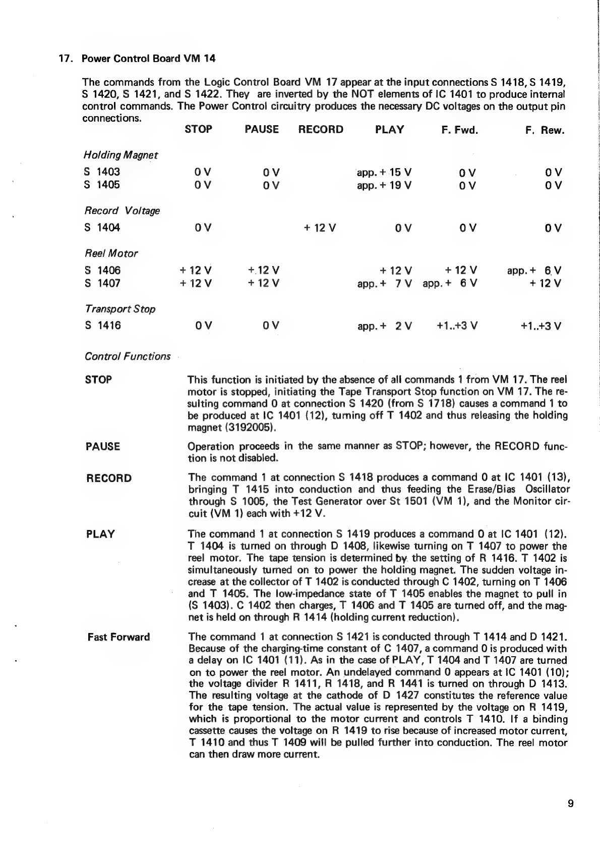
17.
Power
Control
Board
VM
14
The
commands
from
the
Logic
Control
Board
VM
17
appear
at
the
input
connections
S
1418,
S
1419,
S
1420,
S
1421,
and
S
1422.
They
are
inverted
by
the
NOT
elements
of
IC
1401
to
produce
internal
control
commands.
The
Power
Control
circuitry
produces
the
necessary
DC
voltages
on
the
output
pin
connections.
Holding
Magnet
S
1403
S
1405
Record
Voltage
S
1404
Reel
Motor
S
1406
S
1407
Transport
Stop
S
1416
Control
Functions
STOP
PAUSE
RECORD
PLAY
Fast
Forward
STOP
PAUSE
RECORD
PLAY
F.
Fwd.
F.
Rew.
OV
OV
app.+
15
V
ov OV
OV
OV
app.
+
19
V
OV OV
OV
+12V
OV
OV OV
+12V
+12V
+12V +12V
app.+
6V
+12V
+12V
app.+
7V
app.+
6V
+12V
OV
OV
app.+
2V
+1.43
V
+1.43V
This
function
is
initiated
by
the
absence
of
all
commands
1
from
VM
17.
The
reel
motor
is
stopped,
initiating
the
Tape
Transport
Stop
function
on
VM
17.
The
re-
sulting
command
0
at
connection
S
1420
(from
S
1718)
causes
a
command
1
to
be
produced
at
IC
1401
(12),
turning
off
T
1402
and
thus
releasing
the
holding
magnet
(3192005).
Operation
proceeds
in
the
same
manner
as
STOP;
however,
the
RECORD
func-
tion
is
not
disabled.
The
command
1
at
connection
S
1418
produces
a
command
0
at
IC
1401
(13),
bringing
T
1415
into
conduction
and
thus
feeding
the
Erase/Bias
Oscillator
through
S
1005,
the
Test
Generator
over
St
1501
(VM
1),
and
the
Monitor
cir-
cuit
(VM
1)
each
with
+12
V.
The
command
1
at
connection
S
1419
produces
a
command
0
at
IC
1401
(12).
T
1404
is
turned
on
through
D
1408,
likewise
turning
on
T
1407
to
power
the
reel
motor.
The
tape
tension
is
determined
by.
the
setting
of
R
1416.
T
1402
is
simultaneously
turned
on
to
power
the
holding
magnet.
The
sudden
voltage
in-
crease
at
the
collector
of
T
1402
is
conducted
through
C
1402,
turning
on
T
1406
and
T
1405.
The
low-impedance
state
of
T
1405
enables
the
magnet
to
pull
in
(S
1403).
C
1402
then
charges,
T
1406
and
T
1405
are
turned
off,
and
the
mag-
net
is
held
on
through
R
1414
(holding
current
reduction).
The
command
7
at
connection
S
1421
is
conducted
through
T
1414
and
D
1421.
Because
of
the
charging-time
constant
of
C
1407,
acommand
0
is
produced
with
a
delay
on
IC
1401
(11).
As
in
the
case
of
PLAY,
T
1404
and
T
1407
are
turned
on
to
power
the
reel
motor.
An
undelayed
command
0
appears
at
IC
1401
(10);
the
voltage
divider
R
1411,
R
1418,
and
R
1441
is
turned
on
through
D
1413.
The
resulting
voltage
at
the
cathode
of
D
1427
constitutes
the
reference
value
for
the
tape
tension.
The
actual
value
is
represented
by
the
voltage
on
R
1419,
which
is
proportional
to
the
motor
current
and
controls
T
1410.
If
a
binding
cassette
causes
the
voltage
on
R
1419
to
rise
because
of
increased
motor
current,
T
1410
and
thus
T
1409
will
be
pulled
further
into
conduction.
The
reel
motor
can
then
draw
more
current.

10
Fast
Rewind
The
voltage
pulses
for
the
Tape
Transport
Stop
on
VM
17
are
also
derived
at
R
1419.
When
the
Fast
Forward
command
first
appears,
C
1405
causes
somewhat
less
current
to
be
fed
through
T
1409
to
the
reel
motor.
Initially,
therefore,
the
motor
runs
slower
until
the
capacitor
has
charged.
When
the
Fast
Forward
function
is
disabled,
the
cathodes
of
D
1415
and
D
1420
remain
at
0
until
C
1407
has
discharged.
In
this
manner,
a
PLAY
or
Fast
Rewind
command
will
initially
be
blocked
and
appears
only
with
delay
at
IC
1401.
Operation
proceds
in
a
similar
manner
to
Fast
Forward.
A
command
1
at
connec-
tion
S
1422
produces
a
command
0
at
IC
1401
(15).
T
1403
and
T
1408
are
turned
on,
causing
the
reel
motor
to
run
in
reverse.
The
motor
current
is
con-
trolled
the
same
as
for
Fast
Forward.
However,
if
the
MEMORY
contact
is
closed,
C
1408
is
shorted
over
S
1408,
and
the
Rewind
function
proceeds
at
reduced
speed.
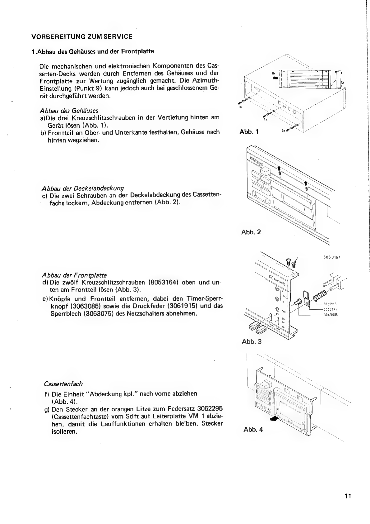
VORBEREITUNG
ZUM
SERVICE
1.Abbau
des
Gehduses
und
der
Frontplatte
Die
mechanischen
und
elektronischen
Komponenten
des
Cas-
setten-Decks
werden
durch
Entfernen
des
Gehauses
und
der
Frontplatte
zur
Wartung
zuganglich
gemacht.
Die
Azimuth-
Einstellung
(Punkt
9)
kann
jedoch
auch
bei
geschlossenem
Ge-
rat
durchgefiihrt
werden.
Abbau
des
Gehdauses
a)Die
drei
Kreuzschlitzschrauben
in
der
Vertiefung
hinten
am
Gerat
lGsen
(Abb.
1).
b)
Frontteil
an
Ober-
und
Unterkante
festhalten,
Gehaduse
nach
hinten
wegziehen.
Abbau
der
Deckelabdeckung
c)
Die
zwei
Schrauben
an
der
Deckelabdeckung
des
Cassetten-
fachs
lockern,
Abdeckung
entfernen
(Abb.
2).
Abbau
der
Frontplatte
d)
Die
zwolf
Kreuzschlitzschrauben
(8053164)
oben
und
un-
ten
am
Frontteil
ldsen
(Abb.
3).
e)Knépfe
und
Frontteil
entfernen,
dabei
den
Timer-Sperr-
knopf
(3063085)
sowie
die
Druckfeder
(3061915)
und
das
Sperrblech
(3063075)
des
Netzschalters
abnehmen.
Cassettenfach
f)
Die
Einheit
“Abdeckung
kpl.”
nach
vorne
abziehen
(Abb.
4).
g)
Den
Stecker
an
der
orangen
Litze
zum
Federsatz
3062295
(Cassettenfachtaste)
vom
Stift
auf
Leiterplatte
VM
1
abzie-
hen,
damit
die
Lauffunktionen
erhalten
bleiben.
Stecker
isolieren.
Pe
Jy
3061915
3063075
3063085
eo
11
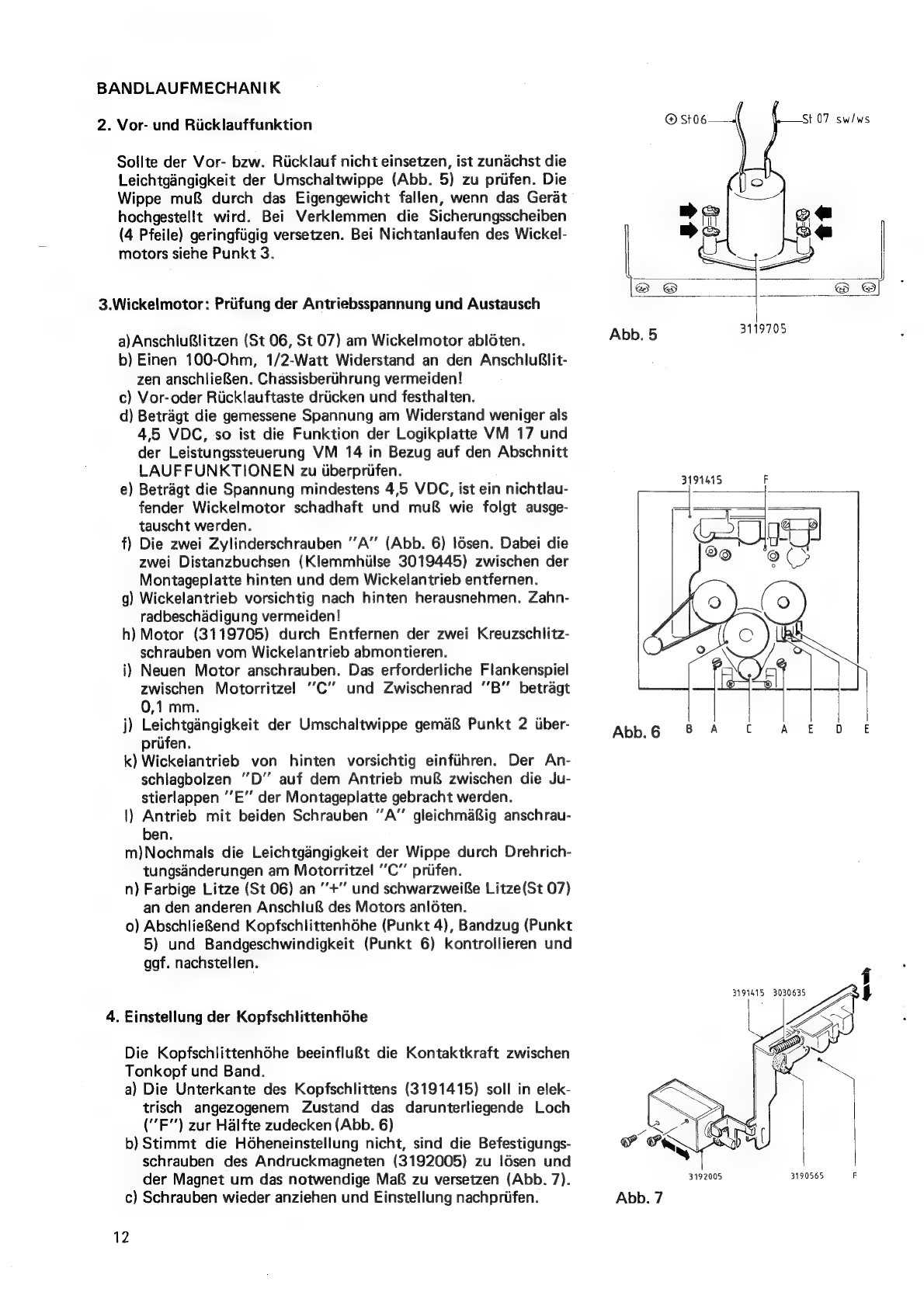
BANDLAUFMECHANIK
2.
Vor-
und
Riicklauffunktion
®
St06
St
07
sw/ws
Sollte
der
Vor-
bzw.
Riicklauf
nicht
einsetzen,
ist
zunachst
die
Leichtgangigkeit
der
Umschaltwippe
(Abb.
5)
zu
priifen.
Die
Wippe
mu&
durch
das
Eigengewicht
fallen,
wenn
das
Gerat
hochgestellt
wird.
Bei
Verklemmen
die
Sicherungsscheiben
(4
Pfeile)
geringfiigig
versetzen.
Bei
Nichtanlaufen
des
Wickel-
motors
siehe
Punkt
3.
3.Wickelmotor:
Priifung
der
Antriebsspannung
und
Austausch
a)AnschluRlitzen
(St
06,
St
07)
am
Wickelmotor
abléten.
Abb.
5
pee
b)
Einen
100-Ohm,
1/2-Watt
Widerstand
an
den
AnschluBlit-
zen
anschlieRen.
Chassisberiihrung
vermeiden!
c)
Vor-oder
Riicklauftaste
driicken
und
festhalten.
d)
Betragt
die
gemessene
Spannung
am
Widerstand
weniger
als
4,5
VDC,
so
ist
die
Funktion
der
Logikplatte
VM
17
und
der
Leistungssteuerung
VM
14
in
Bezug
auf
den
Abschnitt
LAUFFUNKTIONEN
zu
iberpriifen.
e)
Betragt
die
Spannung
mindestens
4,5
VDC,
ist
ein
nichtlau-
ll
fender
Wickelmotor
schadhaft
und
mu&
wie
folgt
ausge-
|
¥
|
tauscht
werden.
|
f)
Die
zwei
Zylinderschrauben
'’A”
(Abb.
6)
Idsen.
Dabei
die
me)
ce
zwei
Distanzbuchsen
(Klemmhiilse
3019445)
zwischen
der
9
9
(>
Montageplatte
hinten
und
dem
Wickelantrieb
entfernen.
g)
Wickelantrieb
vorsichtig
nach
hinten
herausnehmen.
Zahn-
radbeschadigung
vermeiden!
h)
Motor
(3119705)
durch
Entfernen
der
zwei
Kreuzschlitz-
schrauben
vom
Wickelantrieb
abmontieren.
i)
Neuen
Motor
anschrauben.
Das
erforderliche
Flankenspiel
zwischen
Motorritzel
’C’’
und
Zwischenrad
'B’”’
betragt
0,1
mm.
j)
Leichtgangigkeit
der
Umschaltwippe
gema&
Punkt
2
itiber-
prifen.
k)
Wickelantrieb
von
hinten
vorsichtig
einfuhren.
Der
An-
schlagboizen
"D’
auf
dem
Anitrieb
muf&
zwischen
die
Ju-
stierlappen
’’E”
der
Montageplatte
gebracht
werden.
1)
Antrieb
mit
beiden
Schrauben
A”
gleichmafsig
anschrau-
ben.
m)Nochmals
die
Leichtgangigkeit
der
Wippe
durch
Drehrich-
tungsdanderungen
am
Motorritzel
C’’
prifen.
n)
Farbige
Litze
(St
06)
an
+”
und
schwarzweiRe
Litze(St
07)
an
den
anderen
Anschlu&
des
Motors
anloten.
o)
AbschlieRend
Kopfschlittenhdhe
(Punkt
4),
Bandzug
(Punkt
5)
und
Bandgeschwindigkeit
(Punkt
6)
kontrollieren
und
ggf.
nachstellen.
3191415
3030635
H
4.
Einstellung
der
Kopfschlittenhohe
L«
:
AL)
v
Die
Kopfschlittenhohe
beeinflu&t
die
Kontaktkraft
zwischen
Tonkopf
und
Band.
a)
Die
Unterkante
des
Kopfschlittens
(3191415)
soll
in
elek-
trisch
angezogenem
Zustand
das
darunterliegende
Loch
("F’)
zur
Halfte
zudecken
(Abb.
6)
b)
Stimmt
die
Hdheneinstellung
nicht,
sind
die
Befestigungs-
schrauben
des
Andruckmagneten
(3192005)
zu
Idsen
und
der
Magnet
um
das
notwendige
Maf&
zu
versetzen
(Abb.
7).
c)
Schrauben
wieder
anziehen
und
Einstellung
nachpriifen.
12
5.
Einstellung
des
Bandzuges
a)
Bandzugcassette
(Torque
Meter)
einlegen.
b)
Bei
laufender
Cassette
(PLAY)
mittels
R
1416
(Platte
VM
14)
den
Aufwickelzug
zwischen
40
und
45
g—cm
ein-
stellen.
.
c)
Der
Abwickelzug
soll
bei
8
bis
10
g—cm
liegen.
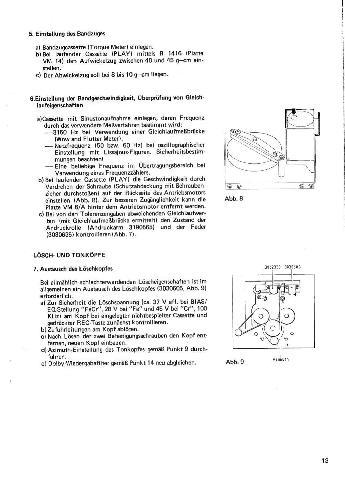
6.Einstellung
der
Bandgeschwindigkeit,
Uberpriifung
von
Gleich-
laufeigenschaften
a)Cassette
mit
Sinustonaufnahme
einlegen,
deren
Frequenz
durch
das
verwendete
MeRverfahren
bestimmt
wird:
——3150
Hz
bei
Verwendung
einer
GleichlaufmeRbriicke
(Wow
and
Flutter
Meter).
——Netzfrequenz
(50
bzw.
60
Hz)
bei
oszillographischer
Einstellung
mit
Lissajous-Figuren.
Sicherheitsbestim-
mungen
beachten!
——Eine
beliebige
Frequenz
im
Ubertragungsbereich
bei
Verwendung
eines
Frequenzzahlers.
b)
Bei
laufender
Cassette
(PLAY)
die
Geschwindigkeit
durch
Verdrehen
der
Schraube
(Schutzabdeckung
mit
Schrauben-
zieher
durchstof&%en)
auf der
Riickseite
des
Antriebsmotors
einstellen
(Abb.
8).
Zur
besseren
Zuganglichkeit
kann
die
Platte
VM
6/A
hinter
dem
Antriebsmotor
entfernt
werden.
c)
Bei
von
den
Toleranzangaben
abweichenden
Gleichlaufwer-
ten
(mit
GleichlaufmeRbriicke
ermittelt)
den
Zustand
der
Andruckrolle
(Andruckarm
3190565)
und
der
Feder
(3030635)
kontrollieren
(Abb.
7).
LOSCH-
UND
TONKOPFE
7.
Austausch
des
Loschkopfes
Bei
allmahlich
schlechterwerdenden
Léscheigenschaften
ist
im
allgemeinen
ein
Austausch
des
Léschkopfes
(3030605,
Abb.
9)
erforderlich.
a)
Zur
Sicherheit
die
Léschspannung
(ca.
37
V
eff.
bei
BIAS/
EQ-Stellung
“FeCr’’,
28
V
bei
Fe”
und
45
V
bei
Cr’,
100
KHz)
am
Kopf
bei
eingelegter
nichtbespielter
Cassette
und
gedriickter
REC-Taste
zunachst
kontrollieren.
b)
Zufuhrleitungen
am
Kopf
abioten.
c)
Nach
Lésen
der
zwei
Befestigungsschrauben
den
Kopf
ent-
fernen,
neuen
Kopf
einbauen.
d)
Azimuth-Einstellung
des
Tonkopfes
gema&
Punkt
9
durch-
fiihren.
e)
Dolby-Wiedergabefilter
gema&
Punkt
14
neu
abgleichen.
Abb.
8
3062335
3030605
|
3)
Abb.
9
Azimuth
13
8.Austausch
des
Tonkopfes
Sollten
Pegelverluste
bei
hohen
Frequenzen
gemerkt
werden,
sind
zunachst
die
Abgleich-
und
Priifvorgange
unter
den
Punkten
9,
10
und
13
durchzufiihren.
Lassen
sich
die
Datenangaben
nicht
erzielen,
ist
der
Ton-
kopf
(3062335,
Abb.
9)
folgenderma&en
auszutauschen:
a)
Kopfleitungen
am
Kopfplattchen
abléten.
b)
Linke
Besfestigungsschraube
entfernen,
rechte
Schraube
tockern.
c)
Kopf
entfernen,
neuen
Kopf
montieren,
dabei
linke
Schraube
festziehen,
rechte
Schraube
zunachst
zur
Erzielung
waagerechter
Lage
des
Kopfes
anziehen.
d)
Kopfleitungen
wieder
anléten.
e)
Einstellungen
gema&
Punkte
9
und
11
-
13
durchfiihren.
9.
Azimuth-Einstellung
Die
Azimuth-Einstellung
(Kopf-Taumelung)
kann
ohne
entfernten
Frontteil
durch
das
Zugangsloch
er-
folgen.
a)
Lésch-
und
Tonképfe
entmagnetisieren.
b)
Azimuth-
bzw.
10-KHz-Cassette
einlegen,
an
Ausgangen
L
und
R
Zwei-Kanal-Oszillograph
(Zerhacker-
betrieb)
anschlieBen.
c)
Bei
laufender
Cassette
(PLAY)
rechte
Befestigungsschraube
des
Tonkopfes
(Abb.
9)
fiir
maximale
Ausgangsspannung
und
Phasengleichheit
beider
Kanale
einstellen.
Achtung:
Nebenmaxima
vermeiden!
AUFNAHME-WIEDERGABE-ELEKTRONIK
Vor
den
Priifarbeiten
die
Einstellung
der
Kopfschlittenhédhe
gema&
Punkt
4
nachpriifen,
Képfe
entmagne-
tisieren
und
mit
Alkohol
reinigen.
Die
Uberpriifungs-
bzw.
Abgleicharbeiten
sind
in
der
vorgegebenen
Reihenfolge
durchzufiihren.
Die
Me&-
punkte
MP
1
-
MP
4
sind
auf
Leiterplatte
VM
1
enthalten.
Die
Positionen
anderer
ausgewiesener
Punkte
und
Bauelemente
werden
jeweils
durch
die
erste
bzw.
die
ersten
zwei
Kennziffern
angegeben.
R
1513
ist
daher
auf
Platte
VM
15
zu
finden,
usw.
Alle
Spannungsangaben
sind
auf
O V
bezogen.
10.
Funktionsiiberpriifung
der
Aufnahme-Wiedergabe-Elektronik
a)
Fremdspannungsfilter
(20
Hz
-
20
KHz:
linear)
am
fiir
die
Messungen
beabsichtigten
NF-Millivoltmeter
einschaiten.
b)
333
Hz
Sinuston-Signal
einspeisen,
an
MP
1(L)
und
MP
2(R)
den
Spannungspegel
auf -30
dBm
(ca.
25
mV)
mit
dem
Speisegenereator
oder
den
Reglern
INPUT
einstellen.
La&t
sich
dieser
Pegel
nicht
ein-
stellen,
sind
die
vorhergehenden
Stufen
auf
Defekte
zu
untersuchen.
——Die
Spannungsverstarkung
der
Dolby-Aufnahme-Platte
VM
6/A
betragt
ca.
29
dB,
der
Eingangs-
pegel
an
den
Punkten
S
612(L)
und
S
603(R)
soll
also
um
1
mV
liegen.
——
Die
Spannungswerte
am
MP
1
und
MP
2
und
an
S
614(L)
und
S
605(R)
sollen
in
etwa
gleich
gro&
sein.
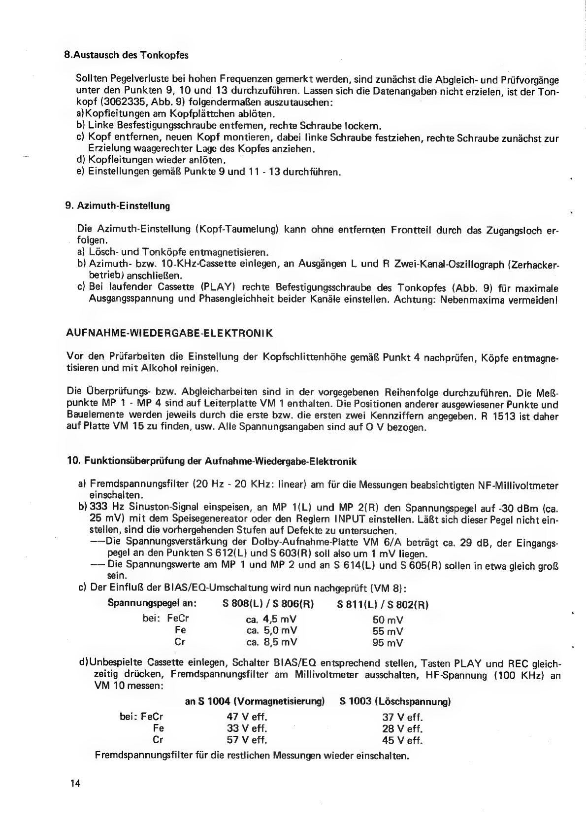
c)
Der
Einflu&
der
BIAS/EQ-Umschaltung
wird
nun
nachgepriift
(VM
8):
Spannungspegel
an:
S$
808(L)
/
S
806(R)
S$
811(L)
/
S
802(R)
bei:
FeCr
ca.
4,5
mV
50
mV
Fe
ca.
5.0mV
55
mV
Cr
ca.
85
mV
95
mV
d)Unbespielte
Cassette
einlegen,
Schalter
BIAS/EQ
entsprechend
stellen,
Tasten
PLAY
und
REC
gleich-
zeitig
driicken,
Fremdspannungsfilter
am
Millivoltmeter
ausschalten,
HF-Spannung
(100
KHz)
an
VM
10
messen:
an
S
1004
(Vormagnetisierung)
|S
1003
(Léschspannung)
bei:
FeCr
47
V
eff.
37
V
eff.
Fe
33
V
eff.
28
V
eff.
Cr
57
V
eff.
45
V
eff.
Fremdspannungsfilter
fur
die
restlichen
Messungen
wieder
einschalten.
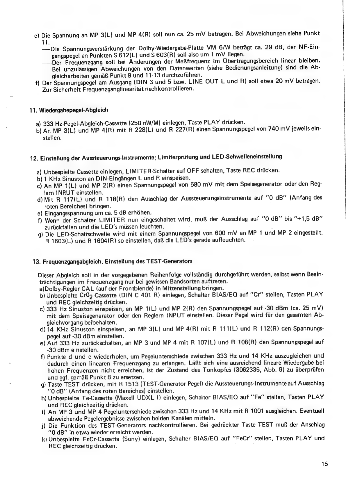
e)
Die
Spannung
an
MP
3(L)
und
MP
4(R)
soll
nun
ca.
25
mV
betragen.
Bei
Abweichungen
siehe
Punkt
11.
——Die
Spannungsverstarkung
der
Dolby-Wiedergabe-Platte
VM
6/W
betragt
ca.
29
dB,
der
NF-Ein-
gangspegel
an
Punkten
S
612(L)
und
S
603(R)
soll
also
um
1
mV
liegen.
——Der
Frequenzgang
soll
bei
Anderungen
der
Meffrequenz
im
Ubertragungsbereich
linear
bleiben.
Bei
unzulassigen
Abweichungen
von
den
Datenwerten
(siehe
Bedienungsanleitung)
sind die
Ab-
gleicharbeiten
gema&
Punkt
9
und
11-13
durchzufihren.
f)
Der
Spannungspegel
am
Ausgang
(DIN
3
und
5
bzw.
LINE
OUT
L
und
R)
soll
etwa
20
mV
betragen.
Zur
Sicherheit
Frequenzganglinearitat
nachkontrollieren.
11.
Wiedergabepegel-Abgleich
a)
333
Hz-Pegel-Abgleich-Cassette
(250
nW/M)
einlegen,
Taste
PLAY
driicken.
b)
An
MP
3(L)
und
MP
4(R)
mit
R
228(L)
und
R
227(R)
einen
Spannungspegel
von
740
mV
jeweils
ein-
stellen.
12.
Einstellung
der
Aussteuerungs-Instrumente;
Limiterprifung
und
LED-Schwelleneinstellung
a)
Unbespielte
Cassette
einlegen,
LIMITER-Schalter
auf
OFF
schalten,
Taste
REC
driicken.
b)
1
KHz
Sinuston
an
DIN-Eingangen
L
und
R
einspeisen.
c)
An
MP
1(L)
und
MP
2(R)
einen
Spannungspegel
von
580
mV
mit
dem
Speisegenerator
oder
den
Reg-
lern
INRUT
einstellen.
d)
Mit
R
117(L)
und
R
118(R)
den
Ausschlag
der
Aussteuerungsinstrumente
auf
“0
dB”
(Anfang
des
roten
Bereiches)
bringen.
e)
Eingangsspannung
um
ca.
5
dB
erhohen.
f)
Wenn
der
Schalter
LIMITER
nun
eingeschaltet
wird,
mu&
der
Ausschlag
auf
0
dB”
bis
"+1,5
dB”
zuriickfallen
und
die
LED’s
miissen
leuchten.
g)
Die
LED-Schaltschwelle
wird
mit
einem
Spannungspegel
von
600
mV
an
MP
1
und
MP
2
eingestelit.
R
1603(L)
und
R
1604(R)
so
einstellen,
da&
die
LED’s
gerade
aufleuchten.
13.
Frequenzgangabgleich,
Einstellung
des
TEST-Generators
Dieser
Abgleich
soll
in
der
vorgegebenen
Reihenfolge
volistandig
durchgefiihrt
werden,
selbst
wenn
Beein-
trachtigungen
im
Frequenzgang
nur
bei
gewissen
Bandsorten
auftreten.
a)Dolby-Regler
CAL
(auf
der
Frontblende)
in
Mittenstellung
bringen.
b)
Unbespielte
Cr02-Cassette
(DIN
C
401
R)
einlegen,
Schalter
BIAS/EQ
auf
Cr”
stellen,
Tasten
PLAY
und
REC
gleichzeitig
driicken.
c)
333
Hz
Sinuston
einspeisen,
an
MP
1(L)
und
MP
2(R)
den
Spannungspegel
auf
-30
dBm
(ca.
25
mV)
mit
dem
Speisegenerator
oder
den
Reglern
INPUT
einstellen.
Dieser
Pegel
wird
fiir
den
gesamten
Ab-
gleichvorgang
beibehalten.
d)
14
KHz
Sinuston
einspeisen,
an
MP
3(L)
und
MP
4(R)
mit
R
111(L)
und
R
112(R)
den
Spannungs-
pegel
auf
-30
dBm
einstellen.
e)
Auf
333
Hz
zuriickschalten,
an
MP
3
und
MP
4
mit
R
107(L)
und
R
108(R)
den
Spannungspegel
auf
-30
dBm
einstellen.
f)
Punkte
d
und
e
wiederholen,
um
Pegelunterschiede
zwischen
333
Hz
und
14
KHz
auszugleichen
und
dadurch
einen
linearen
Frequenzgang
zu
erlangen.
La&t
sich
eine
ausreichend
lineare
Wiedergabe
bei
hohen
Frequenzen
nicht
erreichen,
ist
der
Zustand
des
Tonkopfes
(3062335,
Abb.
9)
zu
tiberpriifen
und
ggf.
gemaR
Punkt
8
zu
ersetzen.
g)
Taste
TEST
driicken,
mit
R
1513
(TEST-Generator-Pegel)
die
Aussteuerungs-Instrumente
auf
Ausschlag
“0
dB”
(Anfang
des
roten
Bereiches)
einstellen.
h)
Unbespielte
Fe-Cassette
(Maxell
UDXL
|)
einlegen,
Schalter
BIAS/EQ
auf
Fe”
stellen,
Tasten
PLAY
und
REC
gleichzeitig
driicken.
;
i)
An
MP
3
und
MP
4
Pegelunterschiede
zwischen
333
Hz
und
14
KHz
mit
R
1001
ausgleichen.
Eventuell
abweichende
Pegelergebnisse
zwischen
beiden
Kanalen
mitteln.
j)
Die
Funktion
des
TEST-Generators
nachkontrollieren.
Bei
gedriickter
Taste
TEST
mu&
der
Anschlag
"0
dB”
in
etwa
wieder
erreicht
werden.
k)
Unbespielte
FeCr-Cassette
(Sony)
einlegen,
Schalter
BIAS/EQ
auf
“FeCr”’
stellen,
Tasten
PLAY
und
REC
gleichzeitig
driicken.
15
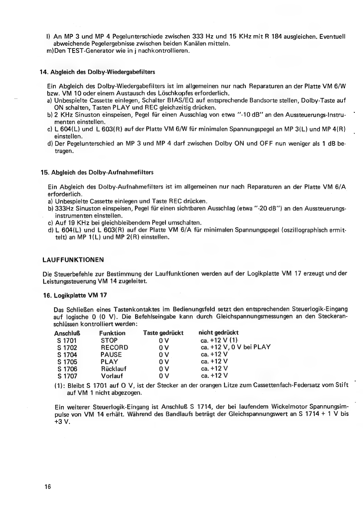
|)
An
MP
3
und
MP
4
Pegelunterschiede
zwischen
333
Hz
und
15
KHz
mit
R
184
ausgleichen.
Eventuell
abweichende
Pegelergebnisse
zwischen
beiden
Kanalen
mittein.
m)Den
TEST-Generator
wie
in
j
nachkontrollieren.
14.
Abgleich
des
Dolby-Wiedergabefilters
Ein
Abgleich
des
Dolby-Wiedergabefilters
ist
im
allgemeinen
nur
nach
Reparaturen
an
der
Platte
VM
6/W
bzw.
VM
10
oder
einem
Austausch
des
Léschkopfes
erforderlich.
a)
Unbespielte
Cassette
einlegen,
Schalter
BIAS/EQ
auf
entsprechende
Bandsorte
stellen,
Dolby-Taste
auf
ON
schalten,
Tasten
PLAY
und
REC
gleichzeitig
driicken.
b)
2
KHz
Sinuston
einspeisen,
Pegel
fiir
einen
Ausschlag
von
etwa
"’-10
dB’”’
an
den
Aussteuerungs-Instru-
menten
einstellen.
c)
L
604(L)
und
L
603(R)
auf
der
Platte
VM
6/W
fiir
minimalen
Spannungspegel
an
MP
3(L)
und
MP
4{R)
einstellen.
d)
Der
Pegelunterschied
an
MP
3
und
MP
4
darf
zwischen
Dolby
ON
und
OFF
nun
weniger
als
1
dB
be-
tragen.
15.
Abgleich
des
Dolby-Aufnahmefilters
Ein
Abgleich
des
Dolby-Aufnahmefilters
ist
im
allgemeinen
nur
nach
Reparaturen
an
der
Platte
VM
6/A
erforderlich.
a)
Unbespielte
Cassette
einlegen
und
Taste
REC
driicken.
b)
333Hz
Sinuston
einspeisen,
Pegel
fiir
einen
sichtbaren
Ausschlag
(etwa
"’-20
dB’’)
an
den
Aussteuerungs-
instrumenten
einstellen.
c)
Auf
19
KHz
bei
gleichbleibendem
Pegel
umschalten.
d)
L
604(L)
und
L
603(R)
auf
der
Platte
VM
6/A
fiir
minimalen
Spannungspegel
(oszillographisch
ermit-
telt)
an
MP
1(L)
und
MP
2(R)
einstellen.
LAUFFUNKTIONEN
Die
Steuerbefehle
zur
Bestimmung
der
Lauffunktionen
werden
auf
der
Logikplatte
VM
17
erzeugt
und
der
Leistungssteuerung
VM
14
zugeleitet.
16.
Logikplatte
VM
17
Das
SchlieRen
eines
Tastenkontaktes
im
Bedienungsfeld
setzt
den
entsprechenden
Steueriogik-Eingang
auf
logische
0
(0
V).
Die
Befehlseingabe
kann
durch
Gleichspannungsmessungen
an
den
Steckeran-
schliissen
kontrolliert
werden:
Anschlu&
Funktion
Taste
gedriickt
nicht
gedriickt
S
1701
STOP
OV
ca.
+12
V
(1)
S
1702
RECORD
OV
ca.
+12
V,
0
V
bei
PLAY
S
1704
PAUSE
OV
ca.+12
V
S
1705
PLAY
OV
ca.+12
V
S
1706
Ricklauf
OV
ca.
+12
V
S
1707
Vorlauf
OV
ca.+12
V
(1):
Bleibt
S
1701
auf
O
V,
ist
der
Stecker
an
der
orangen
Litze
zum
Cassettenfach-Federsatz
vom
Stift
auf
VM
1
nicht
abgezogen.
Ein
weiterer
Steuerlogik-Eingang
ist
Anschlu&
S
1714,
der
bei
laufendem
Wickelmotor
Spannungsim-
pulse
von
VM
14
erhalt.
Wahrend
des
Bandlaufs
betragt
der
Gleichspannungswert
an
S
1714
+
1
V
bis
+3
V.
16
Table of contents
Languages:


