THORNADO TH-WP30A User manual

TH-WP30A TH-WP40AE
TH-WB80 TH-CP20V TH-CP30V
WATER PUMP
Owner’s Manual


· 1 ·
PREFACE
Thank you for choosing a water pump of our company.
Please keep the owner’s manual for reference.
This manual should be considered a permanent part of the water pump
and should remain with the water pump if it is resold.
The manual instructs the user how to operate the water pump including
before operation to get the best results. If a problem should arise or if you
have any questions about the pump, consult an authorized dealer of our
company.
All information and diagrams of this manual are provided in accordance
with the newest products at the publishing time. If revision or any other
change is made in respect of the information descried in this manual,
making it a little different from the product's actual status,our company
will explain it.Our company reserves the right to make changes at any
time without notice and without incurring any obligation. No part of
this publication may be reproduced without written permission of our
company.

· 2 ·
CONTENTS
CONTENTS
1. SAFETY …………………………………………………………… 3
2. COMPONENT IDENTIFICATION ……………………………… 7
3. CONTROL SYSTEM …………………………………………… 14
4. PRE-OPERATION INSPECTION ……………………………… 17
5. OPERATION …………………………………………………… 22
6. STARTING THE ENGINE ……………………………………… 26
7. STOPPING THE ENGINE ……………………………………… 29
8. MAINTENANCE ……………………………………………… 31
9. STORAGE ……………………………………………………… 36
10. TROUBLESHOOTING ……………………………………… 37
11. ELECTRIC DIAGRAM ……………………………………… 39
12. SPECIFICATION ……………………………………………… 40
· 3 ·
1. SAFETY
Our company's water pump is designed to give safe and reliable service
if operated according to instructions. Read and understand the Owner’s
Manual before operating the water pump. Failure to do so could result in
personal injury or equipment damage.
Safety Messages
Your safety and the safety of others are very important. We have provided
important safety messages in this manual and on water pump and engine.
Please read these messages carefully.
Safety label - on the water pump and engine.
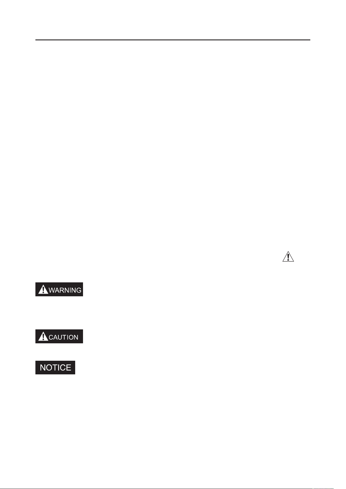
A safety message - alerts you to potential hazards that could hurt you or
others. Each safety message is preceded by a safety alert symbol and
one of three words: WARNING, CAUTION, or NOTICE. These mean:
You CAN be KILLED or SERIOUSLY HURT if you don’t follow
instructions.
You CAN be HURT if you don’t follow instructions.
Your water pump or other property could be damaged if you don’t follow
instructions.
SAFETY

· 4 ·
1) Safety Instruction
Clean water pump and high pressure pump are only designed for
pumping clean water.
Sewage pump has the apability of transmiting soft solids within the
diameter of 25.4mm
Chemical pumps is used for transmission of weak acid and base (PH4-
11), high ignition temperature liquid and sea water.
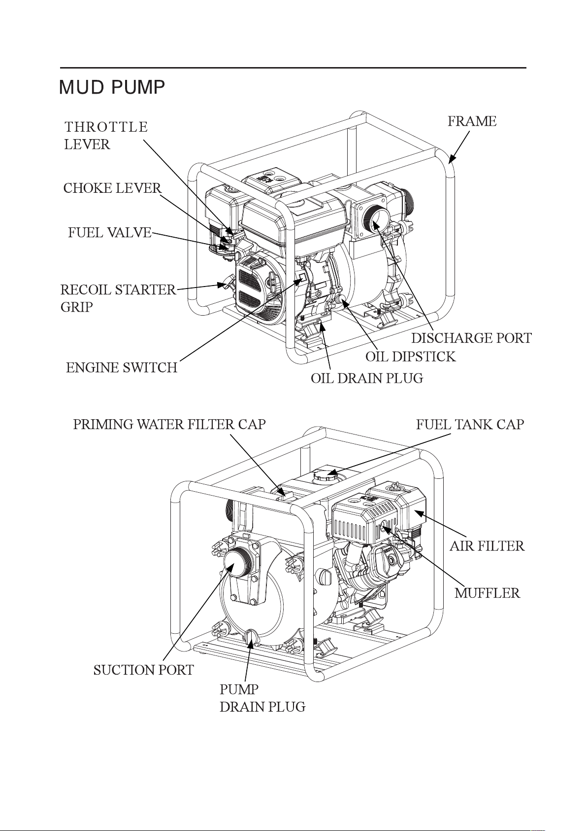
Mud pump is suitable for pumping dirt water with up to 50% solid
sewerge,Capactiy up to diameter of 25.4mm.
To prevent fire hazards and to provide adequate ventilation, keep the
pump at least 1 meter away from each of the building walls and other
equipment during operation. Do not place flammable objects close to
transportation.
The muffler becomes very hot during operation and remains hot for a
it is hot. Let the engine cool before storing the water pump indoors.
and fuel storage area.
Place the pump on a firm, level surface. If the pump is tilted or
overturned, fuel spillage may result.
Refuel in a well-ventilated area with the engine stopped, and in places
for refueling or storing gasoline. If spilling occurs, immediately clean it.
After refueling, cover the fuel tank well and screw it down.
Exhaust contains poisonous carbon monoxide gas that can build up to
dangerous levels in closed areas. Breathing carbon monoxide can cause
unconsciousness or death.
Don’t screw off the plug while the engine is running to avoid damaging
SAFETY
· 5 ·
the equipment and hurting the persons.
Children and pets must be kept away from the area of operation due to a
possibility of burns from the hot engine components.
The machine is forbidden to be operated in a potentially explosive
atmosphere.
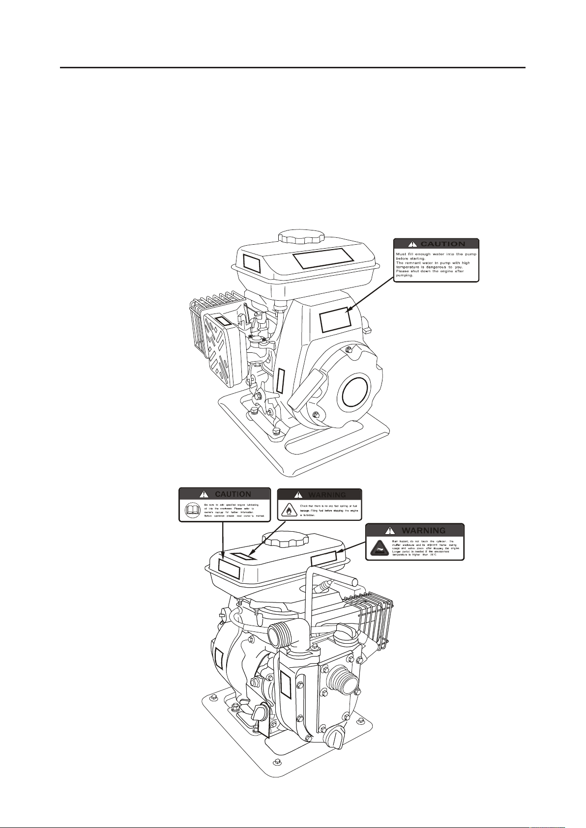
2) Safety Label
SAFETY

· 6 ·
SAFETY
· 7 ·
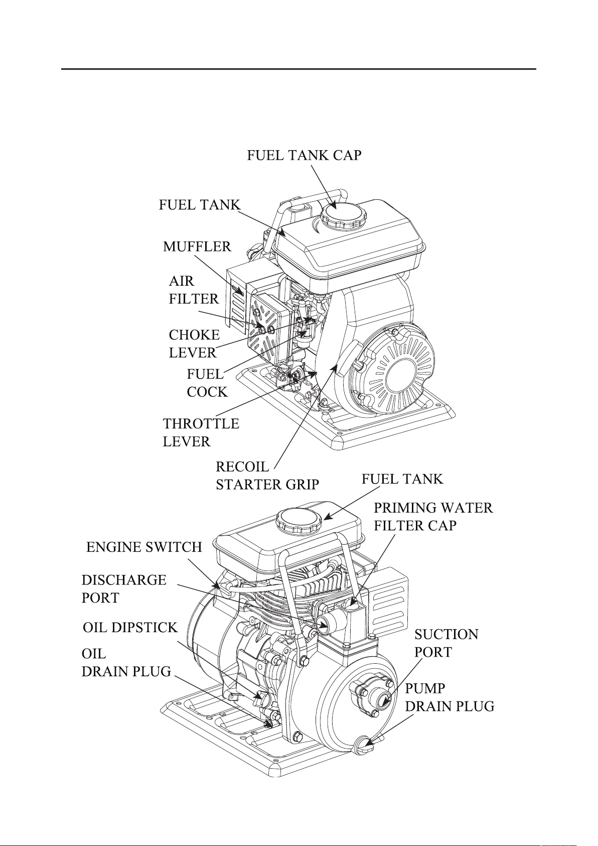
2. COMPONENT IDENTIFICATION
1" CLEAN WATER PUMP
COMPONENT IDENTIFICATION
· 8 ·
COMPONENT IDENTIFICATION
1.5" CLEAN WATER PUMP
AIR
FILTER
RECOIL
STARTER GRIP
CHOKE LEVER
MUFFLER
PRIMING WATER
FILTER CAP
DISCHARGE
PORT
FUEL TANK CAP
FUEL TANK
AIR FILTER
CHOKE
LEVER
FUEL
COCK
RECOIL STARTER GRIP
SPARK PLUG
MUFFLER
ENGINE SWITCH
OIL DIPSTICK
PUMP DRAIN PLUG
PRIMING WATER
FILTER CAP
SUCTION PORT
DISCHARGE PORT
OIL DRAIN PLUG
FUEL TANK
SUCTION PORT
PUMP
DRAIN PLUG
ENGINE SWITCH
FUEL TANK CAP
THROTTLE
LEVER
THROTTLE
LEVER
· 9 ·
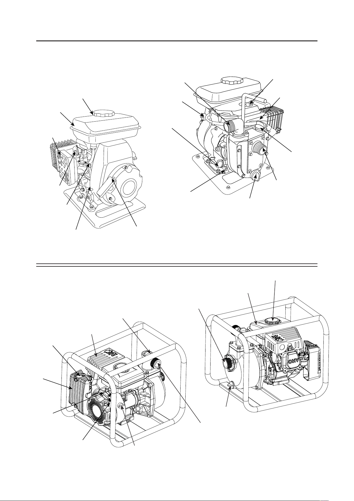
2"/3"/4"/6" CLEAN WATER PUMP
CHOKE LEVER
FUEL TANK CAP
THROTTLE LEVER
DISCHARGE PORT
OIL DIPSTICK
ENGINE SWITCH
RECOIL STARTER GRIP
FUEL COCK
PRIMING WATER FILTER CAP
FRAME
AIR FILTER
MUFFLER
OIL DRAIN PLUG
PUMP DRAIN PLUG
SUCTION PORT
COMPONENT IDENTIFICATION

· 10 ·
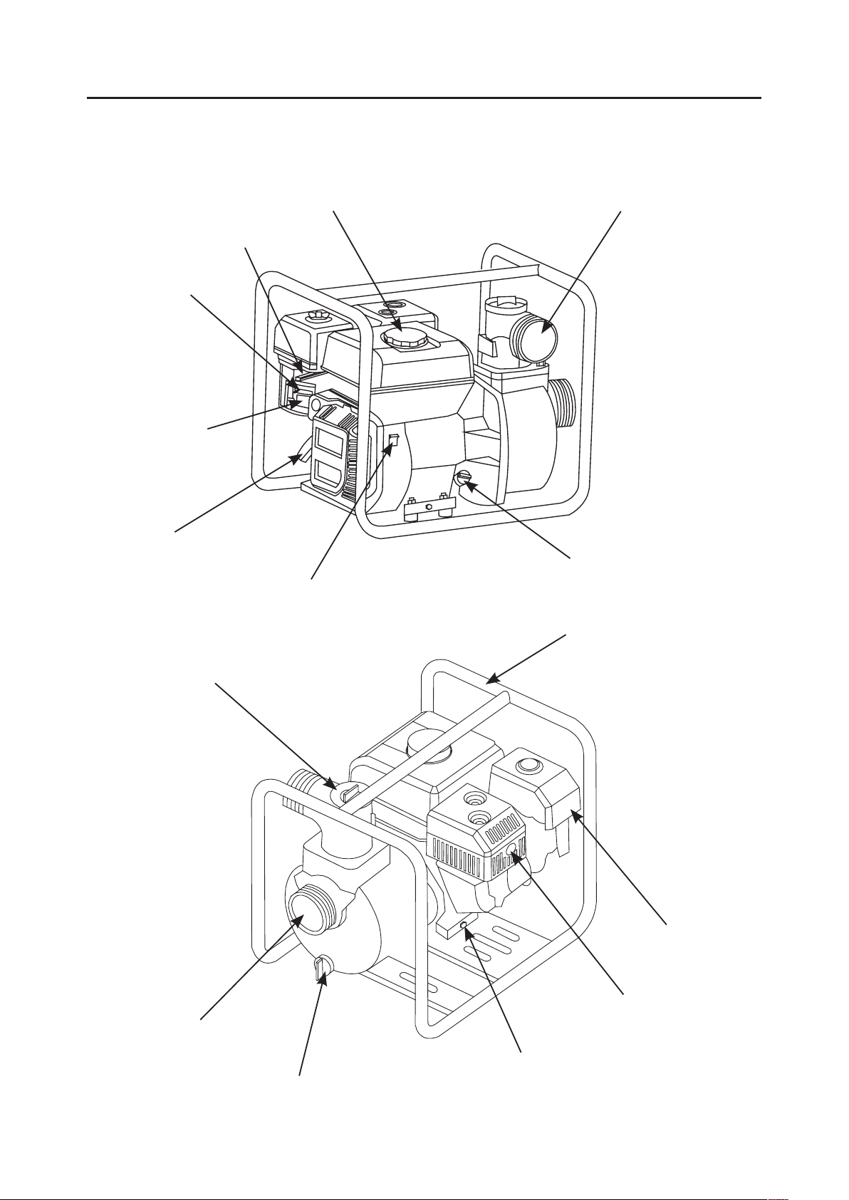
CHEMICAL PUMP
CHOKE LEVER
FUEL VALVE
FUEL TANK CAP
THROTTLE
LEVER
DISCHARGE PORT
OIL DIPSTICK
ENGINE SWITCH
RECOIL STARTER
GRIP
PRIMING WATER FILTER CAP
FRAME
AIR FILTER
MUFFLER
OIL DRAIN PLUG
PUMP
DRAIN PLUG
SUCTION PORT
COMPONENT IDENTIFICATION

· 11 ·
HIGH PRESSURE PUMP( The illustrations employ the
2" high pressure pump as the example)
CHOKE
LEVER
FUEL
VALVE
FUEL TANK CAP
THROTTLE
LEVER
DISCHARGE
PORT
OIL DIPSTICK
ENGINE SWITCH
RECOIL STARTER
GRIP
OIL DRAIN PLUG
COMPONENT IDENTIFICATION
PRIMING WATER
FILTER CAP
FRAME
AIR
FILTER
MUFFLER
PUMP
DRAIN PLUG
SUCTION
PORT
CHOKE
LEVER
FUEL
VALVE
FUEL TANK CAP
THROTTLE
LEVER
PRIMING WATER
FILTER CAP
OIL DIPSTICK
ENGINE SWITCH
RECOIL STARTER
GRIP
OIL DRAIN PLUG
DISCHARGE
PORT
FRAME
AIR FILTER
MUFFLER
PUMP
DRAIN PLUG
SUCTION
PORT

· 12 ·
SEWAGE PUMP
CHOKE LEVER
FUEL VALVE
FUEL TANK CAP
THROTTLE
LEVER
DISCHARGE PORT
OIL DIPSTICK
ENGINE SWITCH
RECOIL STARTER
GRIP
PRIMING WATER FILTER CAP
FRAME
AIR FILTER
MUFFLER
OIL DRAIN PLUG
PUMP
DRAIN PLUG
SUCTION PORT
COMPONENT IDENTIFICATION
· 13 ·
COMPONENT IDENTIFICATION
· 14 ·
3. CONTROL SYSTEM
Before operating our company's water pump, carefully read and
understand the owner’s manual and be familiar with each control
function. Know how to operate and how to do in a urgency condition.
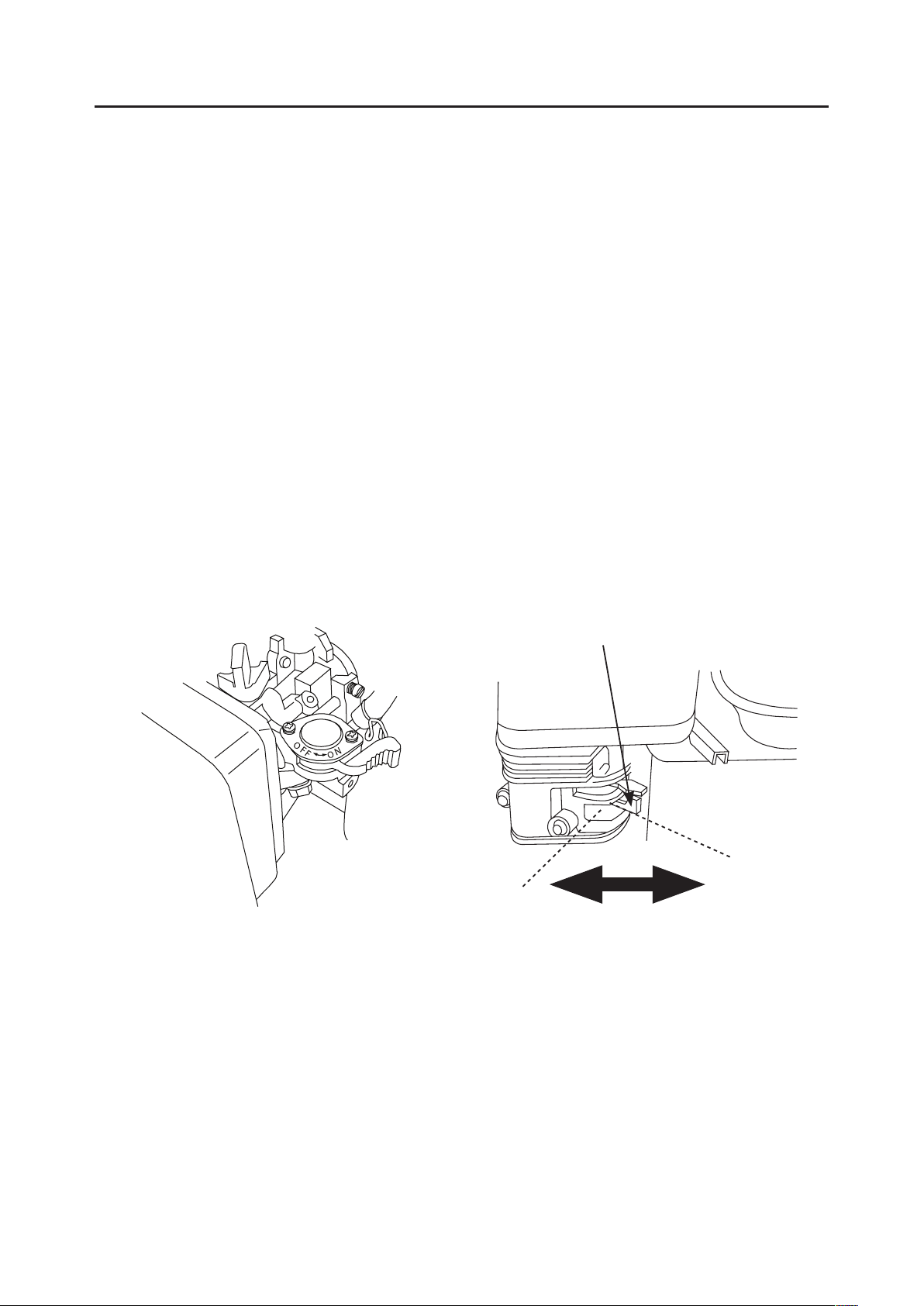
1) Fuel Lever
Set the fuel lever to the “OPEN” position.
When not operating the engine, set the fuel lever to the “CLOSE”
position.
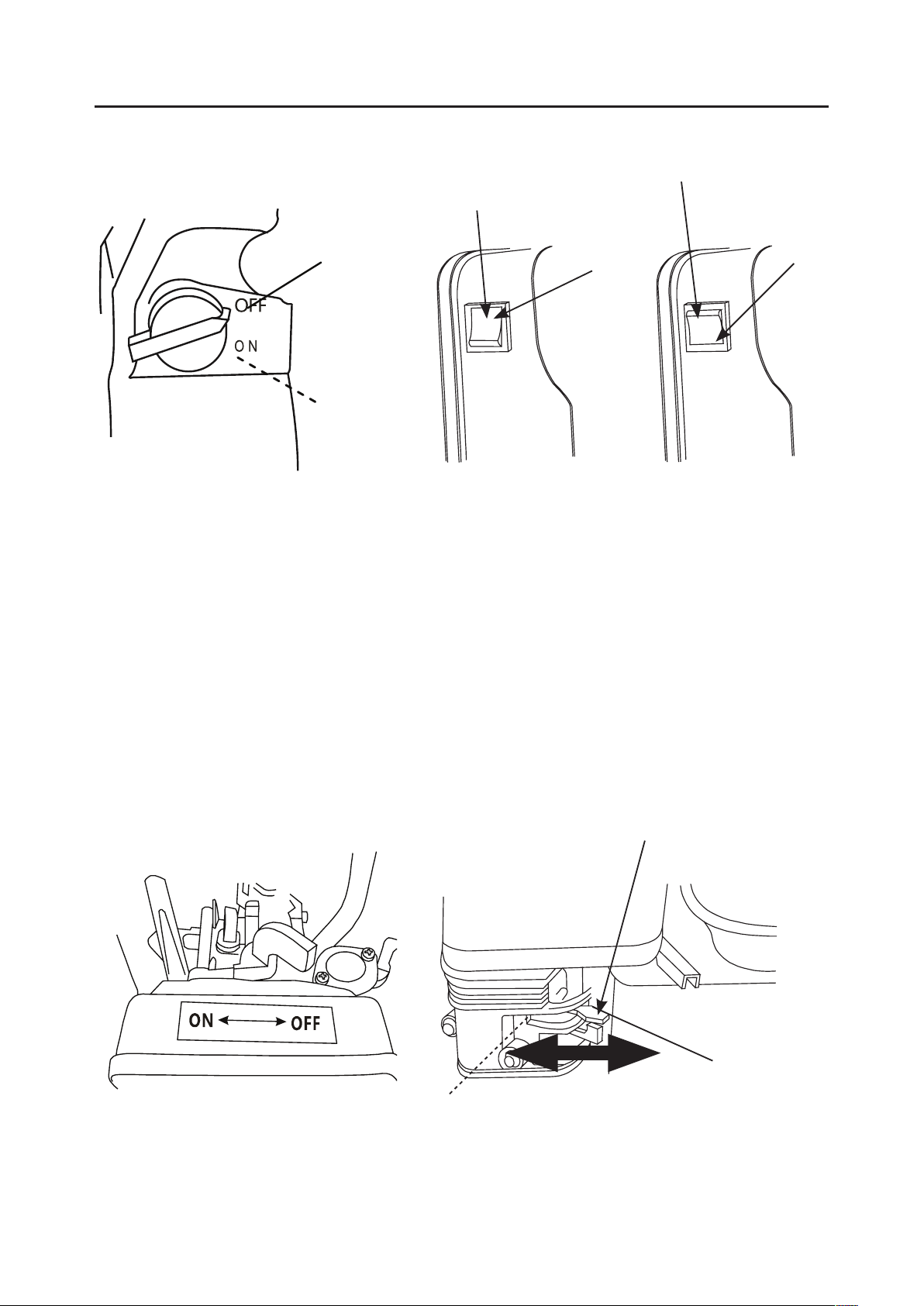
2) Engine Switch
The engine switch is used for opening or closing ignition circuit :
Set the engine switch to the “OPEN” position to run the engine, and set it
to the “CLOSE” position to stop the engine.
FUEL LEVER
CLOSE
OPEN
CONTROL SYSTEM
· 15 ·
3) Choke Lever
The choke lever is used for opening and closing the choke of the
carburetor.
Set the choke lever to the “CLOSE” position for cold starting.
Set the choke lever to the “OPEN” position for normal operation or the
Engine's warm starting.
OPEN
OPEN
CLOSE
CLOSE
ENGINE SWITCH
ENGINE SWITCH
CHOKE LEVER
CLOSE
OPEN
CONTROL SYSTEM
· 16 ·
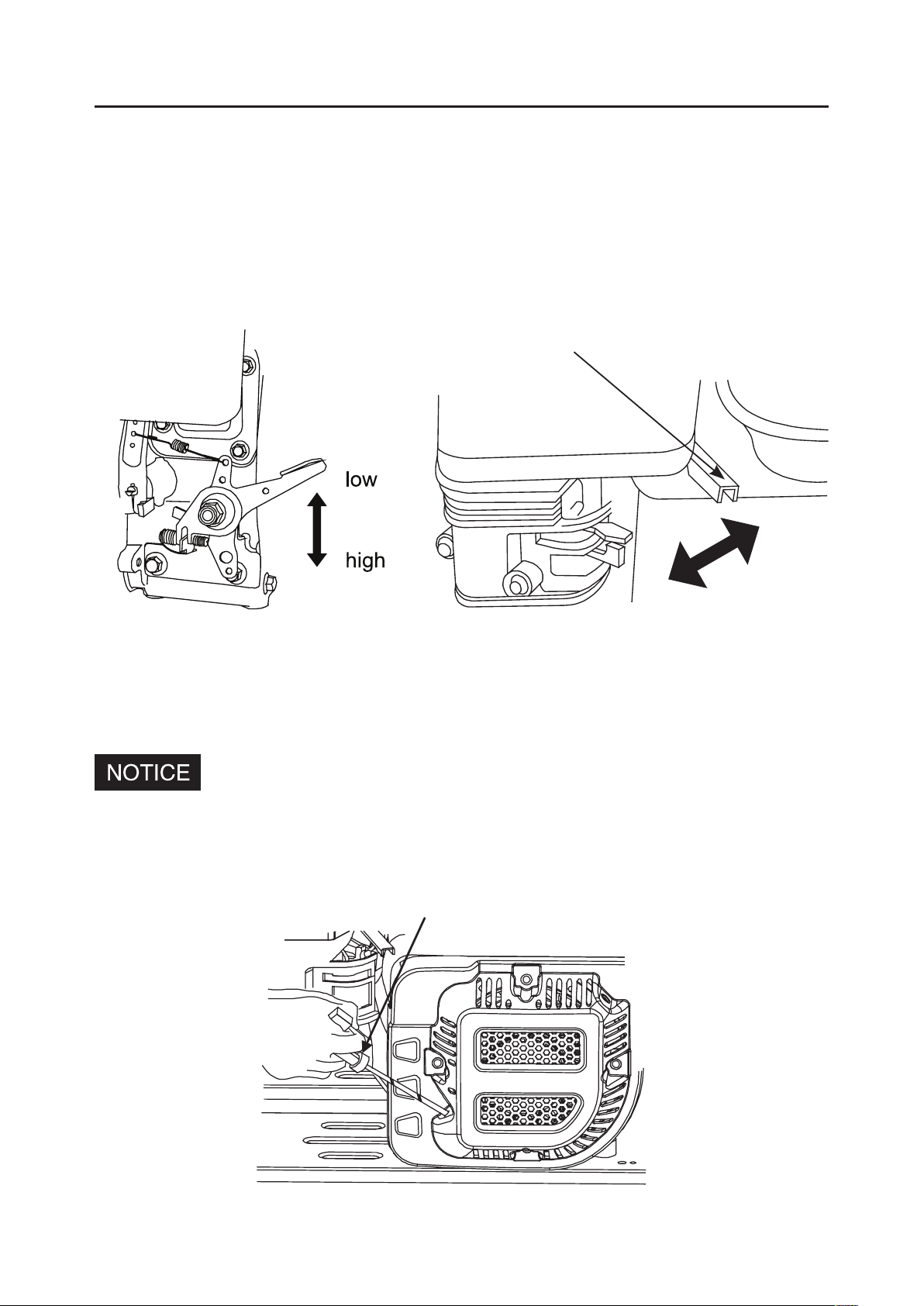
4) Throttle Lever
Adjust the throttle lever to change speed of the engine, thereby adjust the
discharge water. For a bigger water discharge, set the throttle lever to the
HIGH position, for a smaller water discharge, set the throttle lever to the
LOW position.
5) Recoil Starter
Pull the recoil starter to start the engine.
Don’t allow the starter grip to snap back against the engine. Return
it gently to prevent damage to the starter
STARTER GRIP
CONTROL SYSTEM
THROTTLE LEVER
HIGH
LOW

· 17 ·
4. PRE-OPERATION INSPECTION
For your safety and to maximize the service life of your equipment, it is
very important to take a few moments before you operate the pump to
your servicing dealer correct it, before you operate the pump.
Improperly maintaining this pump or failing to correct problems
before operation could cause a malfunction in which you could be
seriously injured.
Exhaust gas contains poisonous carbon monoxide. Avoid inhalation of
exhaust gas. Never run the engine in a closed garage or an enclosed area.
To prevent fire hazards, keep the pump at least 1m away from each of
the building walls and other equipment during operation. Do not place
Before beginning your pre-operation checks, be sure the pump is on a
level surface and the ignition switch is in the OFF position.
1) Routine Check
Look around and underneath the pump for signs of oil or gasoline leaks.
Remove any excessive dirt or debris, especially from around the engine
Look for signs of damage.
are tightened.
PRE-OPERATION INSPECTION

· 18 ·
2) Check The Suction And Discharge Hoses
Check the general condition of the hoses. Be sure the hoses are in
serviceable condition before connecting them to the pump. Remember
that the suction hose must be of a reinforced construction to prevent hose
collapse.
Check to ensure that the sealing washer in the suction hose connector is
in a good condition.
Check to ensure that the hose connectors and clamps are securely
installed.
Check to ensure that the strainer is in a good condition and is installed on
the suction hose.
3) Check Engine Oil
Put the engine on a level place and check the engine oil.
screwing it in.
3) If the level is low, add the recommended oil to the upper mark on the
dipstick.
PRE-OPERATION INSPECTION
This manual suits for next models
4
Table of contents
Popular Water Pump manuals by other brands

Uponor
Uponor CPG Mounting instructions

Grundfos
Grundfos PS.R.05 Installation and operating instructions

Flotec
Flotec FPSC2150A owner's manual

Ingersoll-Rand
Ingersoll-Rand ARO 66605 Series Operator's manual

Pfeiffer Vacuum
Pfeiffer Vacuum HIPACE 2300 I operating instructions

Salamander
Salamander RGP installation guide


GORMAN-RUPP PUMPS
GORMAN-RUPP PUMPS D Series Installation, operation, and maintenance manual with parts list

KSB
KSB Delta Macro F Installation & operating manual

Server
Server CP-MEC3 manual

Wilden
Wilden PS 4 Stallion Metal Engineering, operation & maintenance

IBO
IBO IVO 25-40/180 manual

Barmesa Pumps
Barmesa Pumps BMV Series Installation, operation & maintenance manual