Thorne & Derrick VEGAPULS 67 User manual

Operating Instructions
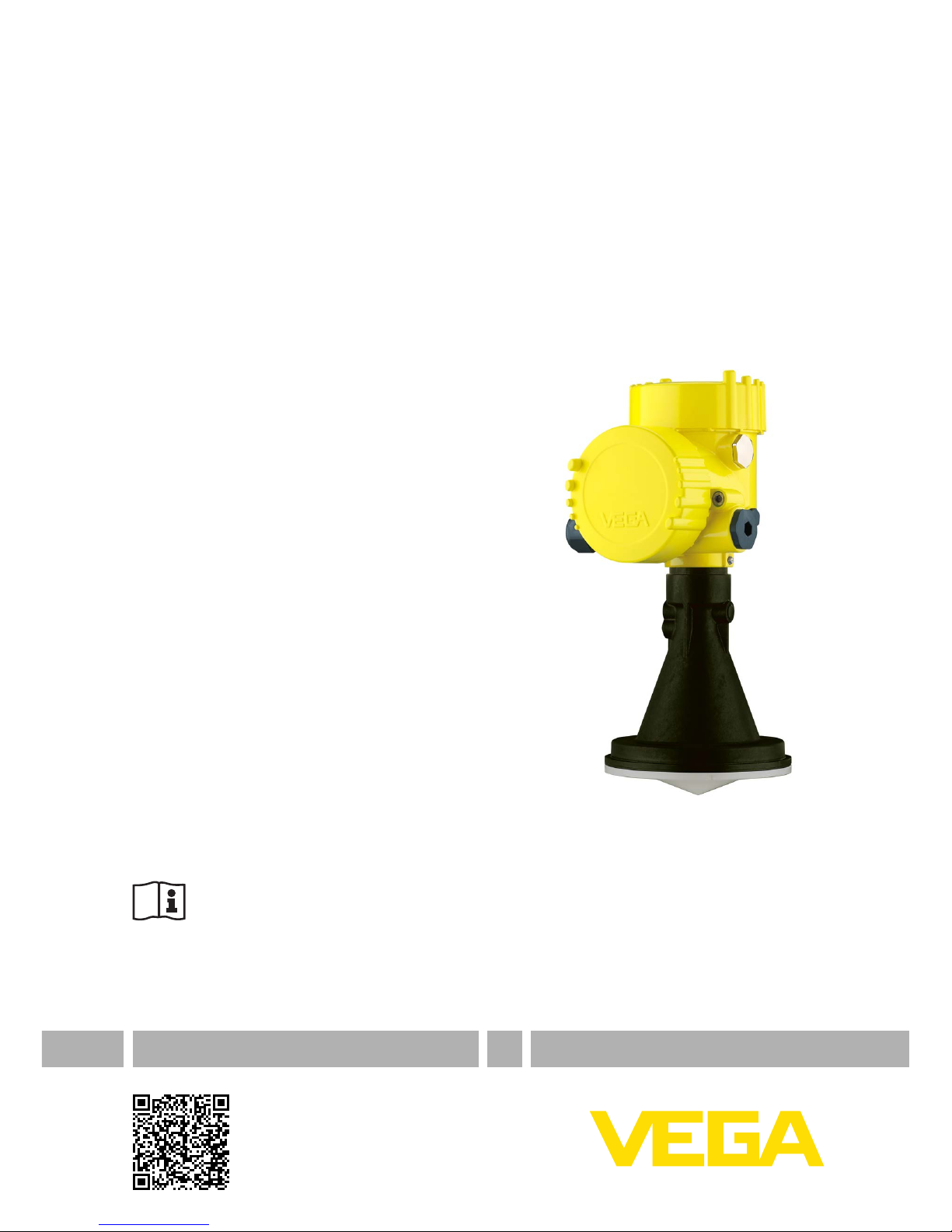
VEGAPULS 67
4 … 20 mA/HART - four-wire
Document ID: 32939

2
Contents
VEGAPULS 67 • 4 … 20 mA/HART - four-wire
32939-EN-150630
Contents
1 About this document
1.1 Function ........................................................................................................................... 4
1.2 Target group ..................................................................................................................... 4
1.3 Symbols used................................................................................................................... 4
2 For your safety
2.1 Authorised personnel ....................................................................................................... 5
2.2 Appropriate use................................................................................................................ 5
2.3 Warning about incorrect use............................................................................................. 5
2.4 General safety instructions............................................................................................... 5
2.5 Safety label on the instrument .......................................................................................... 5
2.6 CE conformity................................................................................................................... 6
2.7 FulllmentofNAMURrecommendations ......................................................................... 6
2.8 FCC/IC conformity (only for USA/Canada) ....................................................................... 6
2.9 Environmental instructions ............................................................................................... 7
3 Product description
3.1 Conguration.................................................................................................................... 8
3.2 Principle of operation........................................................................................................ 9
3.3 Packaging, transport and storage................................................................................... 10
3.4 Accessories and replacement parts ............................................................................... 11
4 Mounting
4.1 General instructions ....................................................................................................... 13
4.2 Mountingpreparation ..................................................................................................... 15
4.3 Mountinginstructions ..................................................................................................... 17
5 Connecting to power supply
5.1 Preparing the connection ............................................................................................... 22
5.2 Connection procedure.................................................................................................... 23
5.3 Wiring plan, double chamber housing ............................................................................ 24
5.4 Switch-on phase............................................................................................................. 26
6 Set up with the display and adjustment module PLICSCOM
6.1 Short description ............................................................................................................ 27
6.2 Insert display and adjustment module............................................................................ 27
6.3 Adjustment system......................................................................................................... 28
6.4 Setup steps .................................................................................................................... 29
6.5 Menuschematic............................................................................................................. 41
6.10 Saving the parameter adjustment data........................................................................... 43
7 Set up with PACTware and other adjustment programs
7.1 Connect the PC via VEGACONNECT ............................................................................ 44
7.2 Parameter adjustment with PACTware............................................................................ 45
7.3 ParameteradjustmentwithAMS™andPDM................................................................. 46
7.4 Saving the parameter adjustment data........................................................................... 47
8 Maintenanceandfaultrectication
8.1 Maintenance,cleaning ................................................................................................... 48
8.2 Rectify faults................................................................................................................... 48
8.3 Exchanging the electronics module................................................................................ 49
8.4 Software update ............................................................................................................. 50

3
Contents
VEGAPULS 67 • 4 … 20 mA/HART - four-wire
32939-EN-150630
8.5 How to proceed if a repair is necessary.......................................................................... 50
9 Dismount
9.1 Dismounting steps.......................................................................................................... 51
9.2 Disposal ......................................................................................................................... 51
10 Supplement
10.1 Technical data ................................................................................................................ 52
10.2 Dimensions .................................................................................................................... 56
Safety instructions for Ex areas
TakenoteoftheExspecicsafetyinstructionsforExapplications.
These instructions are attached as documents to each instrument
with Ex approval and are part of the operating instructions manual.
Editing status: 2015-06-26

4
1 About this document
VEGAPULS 67 • 4 … 20 mA/HART - four-wire
32939-EN-150630
1 About this document
1.1 Function
This operating instructions manual provides all the information you
need for mounting, connection and setup as well as important instruc-
tionsformaintenanceandfaultrectication.Pleasereadthisinforma-
tion before putting the instrument into operation and keep this manual
accessible in the immediate vicinity of the device.
1.2 Target group
This operating instructions manual is directed to trained specialist
personnel.The contents of this manual should be made available to
these personnel and put into practice by them.
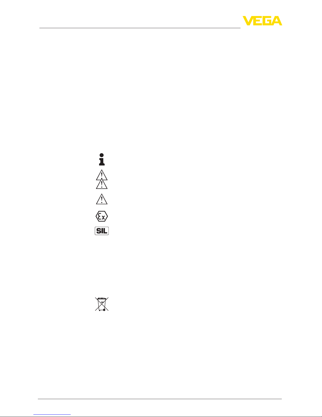
1.3 Symbols used
Information, tip, note
This symbol indicates helpful additional information.
Caution: If this warning is ignored, faults or malfunctions can result.
Warning: If this warning is ignored, injury to persons and/or serious
damage to the instrument can result.
Danger: If this warning is ignored, serious injury to persons and/or
destruction of the instrument can result.
Ex applications
This symbol indicates special instructions for Ex applications.
SIL applications
This symbol indicates instructions for functional safety which must be
taken into account particularly for safety-relevant applications.
• List
The dot set in front indicates a list with no implied sequence.
→ Action
This arrow indicates a single action.
1 Sequence of actions
Numbers set in front indicate successive steps in a procedure.
Battery disposal
This symbol indicates special information about the disposal of bat-
teries and accumulators.

5
2 For your safety
VEGAPULS 67 • 4 … 20 mA/HART - four-wire
32939-EN-150630
2 For your safety
2.1 Authorised personnel
All operations described in this operating instructions manual must
be carried out only by trained specialist personnel authorised by the
plant operator.
During work on and with the device the required personal protective
equipment must always be worn.
2.2 Appropriate use
VEGAPULS 67 is a sensor for continuous level measurement.
Youcannddetailedinformationabouttheareaofapplicationin
chapter "Product description".
Operational reliability is ensured only if the instrument is properly
usedaccordingtothespecicationsintheoperatinginstructions
manual as well as possible supplementary instructions.
For safety and warranty reasons, any invasive work on the device
beyond that described in the operating instructions manual may be
carried out only by personnel authorised by the manufacturer. Arbi-
traryconversionsormodicationsareexplicitlyforbidden.
2.3 Warning about incorrect use
Inappropriate or incorrect use of the instrument can give rise to
application-specichazards,e.g.vesseloverllordamagetosystem
components through incorrect mounting or adjustment.
2.4 General safety instructions
This is a high-tech instrument requiring the strict observance of stand-
ard regulations and guidelines.The user must take note of the safety
instructionsinthisoperatinginstructionsmanual,thecountry-specic
installation standards as well as all prevailing safety regulations and
accident prevention rules.
Depending on the model, the emitting frequencies of all radar sensors
are either in the C or K band range.The low transmitting power lies far
below the internationally permitted limit values.When the instrument
is used correctly, it presents no danger to human health. It may be
operated without restriction outside of closed metallic vessels.
Theinstrumentmustonlybeoperatedinatechnicallyawlessand
reliable condition.The operator is responsible for trouble-free opera-
tion of the instrument.
During the entire duration of use, the user is obliged to determine the
compliance of the necessary occupational safety measures with the
current valid rules and regulations and also take note of new regula-
tions.
2.5 Safety label on the instrument
The safety approval markings and safety tips on the device must be
observed.

6
2 For your safety
VEGAPULS 67 • 4 … 20 mA/HART - four-wire
32939-EN-150630
2.6 CE conformity
ThedevicefulllsthelegalrequirementsoftheapplicableECguide-
lines.ByaxingtheCEmarking,weconrmsuccessfultestingofthe
product.
YoucanndtheCECerticateofConformityinthedownloadsection
of our homepage.
Electromagnetic compatibility
The instruments are designed for use in an industrial environment.
Nevertheless, electromagnetic interference from electrical conductors
and radiated emissions must be taken into account, as is usual with a
class A instrument according to EN 61326-1. If the instrument is used
inadierentenvironment,itselectromagneticcompatibilitywithother
devices must be ensured by suitable measures.
2.7 FulllmentofNAMURrecommendations
NAMURistheautomationtechnologyuserassociationintheprocess
industryinGermany.ThepublishedNAMURrecommendationsare
acceptedasthestandardineldinstrumentation.
ThedevicefulllstherequirementsofthefollowingNAMURrecom-
mendations:
• NE 21 – Electromagnetic compatibility of equipment
• NE 43 – Signal level for malfunction information from measuring
transducers
• NE53–Compatibilityofelddevicesanddisplay/adjustment
components
For further information see www.namur.de.
2.8 FCC/ICconformity(onlyforUSA/Canada)
The VEGAPULS 67 may only be used in closed vessels made of
metal,concrete,orbre-reinforcedplastic.
Note about this manual:
This operating instructions manual is intended for use in a number
ofdierentcountries.Theillustrationsshowsomeapplicationsof
VEGAPULS 67 in atmospherically open vessels.These applications
are not in conformity with the FCC/IC approvals of the instrument.
VEGAPULS 67 is FCC/IC approved with all the antenna types de-
scribed in this operating instructions manual.
Conversionsormodicationsoftheinstrumentnotexpressivelyap-
proved by VEGA will lead to revocation of the operational release.
The instrument is in compliance with Part 15 of the FCC regulations.
Operationispermittedonlyifthefollowingtwoconditionsarefullled:
1.The instrument must not emit interference radiation and
2.Theinstrumentmustoperateunaectedbyincominginterference
radiation, also by such that may trigger unwanted operating condi-
tions.
The instrument was tested and its compliance with the limit values
for a digital Class A instrument, in conformity with Part 15 of the FCC

7
2 For your safety
VEGAPULS 67 • 4 … 20 mA/HART - four-wire
32939-EN-150630
regulations,determined.Theselimitvaluesarespeciedtoensurea
proper protection against interference radiation during operation in
industrial environments.The instrument generates, uses and can emit
electromagnetic waves. If the instrument is not installed and operated
accordingtothespecicationsofthisoperatinginstructionsmanual,
itcanemitinterferenceradiationthatmayaectcommunication
systems.When the instrument is operated in residential areas, it is the
responsibility of the operator to ensure that any interference radiation
is suppressed.
2.9 Environmental instructions
Protection of the environment is one of our most important duties.
That is why we have introduced an environment management system
with the goal of continuously improving company environmental pro-
tection.Theenvironmentmanagementsystemiscertiedaccording
to DIN EN ISO 14001.
Pleasehelpusfulllthisobligationbyobservingtheenvironmental
instructions in this manual:
• Chapter "Packaging, transport and storage"
• Chapter "Disposal"

8
3 Product description
VEGAPULS 67 • 4 … 20 mA/HART - four-wire
32939-EN-150630
3 Product description
3.1 Conguration
The scope of delivery encompasses:
• Radar sensor
• Documentation
– Quick setup guide VEGAPULS 67
– Instructions for optional instrument features
– Ex-specic"Safety instructions" (with Ex versions)
– ifnecessary,furthercerticates
• DVD "Software", included therein
– PACTware/DTMCollection
– Driver software
Information:
In this operating instructions manual, the optional instrument features
are described.The respective scope of delivery results from the order
specication.
The VEGAPULS 67 consists of the components:
• Processttingwithencapsulatedantennasystem
• Housing with electronics
• Housing cover, optionally available with display and adjustment
modulePLICSCOM
Thecomponentsareavailableindierentversions.
3
2
1
4
Fig. 1: VEGAPULS 67 - threaded version with encapsulated antenna system
and Alu double chamber housing
1 Housing cover with integrated PLICSCOM (optional)
2 Housing with electronics
3 Processttingwithencapsulatedantennasystem
4 Antenna cover
Scope of delivery
Constituent parts

9
3 Product description
VEGAPULS 67 • 4 … 20 mA/HART - four-wire
32939-EN-150630
3
2
1
4
Fig. 2: VEGAPULS 67, threaded version with plastic horn antenna and Alu
double chamber housing
1 Housing cover with integrated PLICSCOM (optional)
2 Housing with electronics
3 Processttingwithplastichornantenna
Thetypelabelcontainsthemostimportantdataforidenticationand
use of the instrument:
• Instrument type
• Article and serial number device
• Article numbers, documentation
• Technicaldata:Approvals,antennatype,processtting,process
seal/temperature, signal output, voltage supply, protection, protec-
tion class
• SILidentication(withSILratingexworks)
With the serial number, you can access the delivery data of the instru-
ment via www.vega.com, "VEGA Tools" and "serial number search".
Youcanndtheserialnumberontheinsideoftheinstrumentaswell
as on the type label on the outside.
This operating instructions manual applies to the following instrument
versions:
• Hardware version < 2.0.0
• Softwareversion≤3.8
3.2 Principle of operation
The VEGAPULS 67 is particularly suitable for measurement of bulk
solids in silos with up to 15 m height.
The antenna of the radar sensor emits short radar pulses with a
durationofapprox.1ns.Thesepulsesarereectedbytheproduct
Type label
Scope of this operating
instructions manual
Area of application
Functional principle

10
3 Product description
VEGAPULS 67 • 4 … 20 mA/HART - four-wire
32939-EN-150630
and received by the antenna as echoes.The transit time of the radar
pulses from emission to reception is proportional to the distance and
hence to the level.The determined level is converted into an appropri-
ate output signal and outputted as measured value.
Four-wire electronics with separate power supply.
Thesupplyvoltagerangecandierdependingontheinstrument
version.
Thedataforpowersupplyarespeciedinchapter"Technical data".
Measuredvaluetransmissioniscarriedoutviathe4…20mA/HART
output separate from power supply.
The backlight of the display and adjustment module is powered by
the sensor. The prerequisite for this is a supply voltage at a certain
level.Theexactvoltagespecicationsarestatedinchapter"Technical
data".
3.3 Packaging, transport and storage
Your instrument was protected by packaging during transport. Its
capacity to handle normal loads during transport is assured by a test
based on ISO 4180.
The packaging of standard instruments consists of environment-
friendly, recyclable cardboard. For special versions, PE foam or PE
foil is also used. Dispose of the packaging material via specialised
recycling companies.
Transport must be carried out in due consideration of the notes on the
transport packaging. Nonobservance of these instructions can cause
damage to the device.
The delivery must be checked for completeness and possible transit
damage immediately at receipt. Ascertained transit damage or con-
cealed defects must be appropriately dealt with.
Up to the time of installation, the packages must be left closed and
stored according to the orientation and storage markings on the
outside.
Unless otherwise indicated, the packages must be stored only under
the following conditions:
• Not in the open
• Dry and dust free
• Not exposed to corrosive media
• Protected against solar radiation
• Avoiding mechanical shock and vibration
• Storage and transport temperature see chapter "Supplement -
Technical data - Ambient conditions"
• Relative humidity 20 … 85 %
Voltage supply
Packaging
Transport
Transport inspection
Storage
Storage and transport
temperature

11
3 Product description
VEGAPULS 67 • 4 … 20 mA/HART - four-wire
32939-EN-150630
3.4 Accessories and replacement parts
ThedisplayandadjustmentmodulePLICSCOMisusedformeasured
value indication, adjustment and diagnosis. It can be inserted into the
sensor and removed at any time.
Youcanndfurtherinformationintheoperatinginstructions"Display
and adjustment module PLICSCOM" (Document-ID 27835).
The interface adapter VEGACONNECT enables the connection of
communication-capable instruments to the USB interface of a PC. For
parameter adjustment of these instruments, an adjustment software
suchasPACTwarewithVEGA-DTMisrequired.
Youcanndfurtherinformationintheoperatinginstructions"Interface
adapter VEGACONNECT" (Document-ID 32628).
The VEGADIS 81 is an external display and adjustment unit for VEGA
plics®sensors.
For sensors with double chamber housing the interface adapter
"DISADAPT" is also required for VEGADIS 81.
Youcanndfurtherinformationintheoperatinginstructions"VE-
GADIS 81" (Document-ID 43814).
VEGADIS 82 is suitable for measured value indication and adjustment
of sensors with HART protocol. It is looped into the 4 … 20 mA/HART
signal cable.
Youcanndfurtherinformationintheoperatinginstructions"VE-
GADIS 82" (Document-ID 45300).
The protective cover protects the sensor housing against soiling and
intense heat from solar radiation.
Youwillndadditionalinformationinthesupplementaryinstructions
manual "Protective cover" (Document-ID 34296).
Flangesareavailableindierentversionsaccordingtothefollowing
standards: DIN 2501, EN 1092-1, ANSI B 16.5, JIS B 2210-1984,
GOST 12821-80.
Youcanndadditionalinformationinthesupplementaryinstructions
manual "Flanges according to DIN-EN-ASME-JIS" (Document-ID
31088).
Thevariableangesealisusedtodirectthesensorantennatothe
bulk solids surface and hence optimise the measurement.
Youcanndadditionalinformationinthesupplementaryinstructions
manual "Variableangeseal" (Document-ID 33797).
The rinsing connection is used to blow compressed air into the
antenna area of the radar sensor. This protects the surfaces of the
antenna system against dust or condensation.
Youwillndadditionalinformationinthesupplementaryinstructions
manual "Rinsing connection" (Document-ID 49552).
PLICSCOM
VEGACONNECT
VEGADIS 81
VEGADIS 82
Protective cap
Flanges
Variableangeseal
Rinsingconnection

12
3 Product description
VEGAPULS 67 • 4 … 20 mA/HART - four-wire
32939-EN-150630
Electronics module "VEGAPULS series 60" is a replacement part for
radarsensorsofVEGAPULSseries60.Adierentversionisavailable
for each type of signal output.
Youcanndfurtherinformationintheoperatinginstructions"Elec-
tronics module VEGAPULS series 60" (Document-ID 30176).
Electronics module

13
4Mounting
VEGAPULS 67 • 4 … 20 mA/HART - four-wire
32939-EN-150630
4 Mounting
4.1 General instructions
Select an installation position you can easily reach for mounting and
connectingaswellaslaterretrottingofadisplayandadjustment
module.The housing can be rotated by 330° without the use of any
tools.You can also install the display and adjustment module in four
dierentpositions(eachdisplacedby90°).
Use the recommended cables (see chapter "Connecting to power
supply") and tighten the cable gland.
You can give your instrument additional protection against moisture
penetration by leading the connection cable downward in front of the
cableentry.Rainandcondensationwatercanthusdraino.Thisap-
plies mainly to outdoor mounting as well as installation in areas where
high humidity is expected (e.g. through cleaning processes) or on
cooled or heated vessels.
Fig. 3: Measures against moisture ingress
In the case of instrument housings with self-sealing NPT threads, it is
not possible to have the cable entries screwed in at the factory. The
free openings for the cable glands are therefore covered with red dust
protection caps as transport protection.
Prior to setup you have to replace these protective caps with ap-
proved cable glands or close the openings with suitable blind plugs.
The reference plane for the measuring range of the sensors is the
bearing surface on the side of the focussing lens. With the version
withadapterange,thereferenceplaneisthelowersideoftheange.
Installation position
Moisture
Cableentries-NPT
thread
Measuring range

14
4Mounting
VEGAPULS 67 • 4 … 20 mA/HART - four-wire
32939-EN-150630
1 32
100%
0%
4
Fig. 4: Measuring range (operating range) and max. measuring distance
1 full
2 empty (max. measuring distance)
3 Measuring range
4 Reference plane
Information:
If the medium reaches the antenna, buildup can form on it and cause
faulty measurements later on.
The emitted radar pulses of VEGAPULS 67 are electromagnetic
waves.They thus have electrical and magnetical components that are
perpendiculartoeachother.Thepolariationplaneisdenedbythedi-
rection of the electrical component.With radar sensors, the polarisa-
tioncanbeusedtoconsiderablyreducetheeectoffalseechoesby
turningtheinstrumentintheconnectionangeormountingboss.The
position of the polarisation plane is marked on the instrument.
1
Fig. 5: Position of the polarisation plane of VEGAPULS 67
1 Marking bars
Polarisation plane

15
4Mounting
VEGAPULS 67 • 4 … 20 mA/HART - four-wire
32939-EN-150630
Makesurethatallpartsoftheinstrumentcomingindirectcontact
with the process, especially the sensor element, process seal and
processtting,aresuitablefortheexistingprocessconditions,such
as process pressure, process temperature as well as the chemical
properties of the medium.
Youcanndthespecicationsinchapter"Technical data" and on the
nameplate.
4.2 Mounting preparation
Theradarsensorcanbemountedintwodierentways:
• with a mounting strap
• viaacollaroradapterange.
The mounting strap enables simple mounting on the vessel wall or
silo top. It is suitable for wall, ceiling or boom mounting. Especially in
openvesselsthisisaveryeasyandeectivewaytoalignthesensor
to the bulk solid surface.
Fig. 6: Radar sensor with mounting strap
The strap is supplied unassembled and must be screwed to the sen-
sorbeforesetupwiththreehexagonsocketscrewsM5x10andspring
washers.Max.torque,seechapter"Technical data". Required tools:
Allenwrenchsize4.
There are two ways to screw the strap onto the sensor. Depending
on the selected version, the sensors can be swivelled in the strap as
follows:
• Single chamber housing
– Angleofinclination180°,innitelyvariable
– Angle of inclination in three steps 0°, 90° and 180°
• Double chamber housing
– Angleofinclination90°,innitelyvariable
– Angle of inclination in two steps 0° and 90°
Suitability for the process
conditions
Mounting strap

16
4Mounting
VEGAPULS 67 • 4 … 20 mA/HART - four-wire
32939-EN-150630
Fig. 7: Adjustment of the angle of inclination
Fig. 8: Turning by fastening in the centre
ThecompressionangeallowsmountingonaangeDN80/ANSI3",
theadapterangeonangesDN100/ANSI4"andDN150/ANSI6"
Youcannddrawingsofthesemountingoptionsinchapter"Dimen-
sions".
Collaroradapterange

17
4Mounting
VEGAPULS 67 • 4 … 20 mA/HART - four-wire
32939-EN-150630
Fig. 9: Flange mounting of the radar sensor
4.3 Mounting instructions
MountVEGAPULS67atleast200mm(7.874in)awayfromtheves-
sel wall.
If you cannot maintain this distance, you should carry out a false
signal storage during setup.This applies particularly if buildup on the
vessel wall is expected. In such cases, we recommend repeating the
false signal storage at a later date with existing buildup.
AcorrespondingcollarangeforDN80(ASME3"orJIS80)aswell
asasuitableadapterangeareavailableformountingVEGAPULS
67.
With the housing versions plastic, aluminium single chamber and
stainlesssteel,thecollarangecanbeplaceddirectlyoverthehous-
ing. With the aluminium double chamber housing, retroactive mount-
inginthiswayisnotpossible-themountingtypemustbespecied
with the order.
Information:
The mounting socket should be as short as possible and its end
rounded.This reduces false echoes from the vessel mounting socket.
Installation position
Socket

18
4Mounting
VEGAPULS 67 • 4 … 20 mA/HART - four-wire
32939-EN-150630
Fig. 10: Recommended socket mounting
Ifthemediumhasgoodreectiveproperties,VEGAPULS67can
also be mounted on a longer socket piece. Recommended values
forsocketheightsarespeciedinthefollowingillustration.Youmust
carry out a false echo storage afterwards.
d
h
The below charts specify the max. pipe socket length h depending on
the diameter d.
Socket diameter d Socket length h
80 mm 300 mm
100 mm 400 mm
150 mm 500 mm
Socket diameter d Socket length h
3" 11.8 in
4" 15.8 in
6" 19.7 in
Tip:
In new facilities it is useful to incline the vessel socket in the direction
oftheoutlet.Falsereectionsfromthevesselwallarethusreduced
and measurement all the way down to the bottom of the conical outlet
is possible.

19
4Mounting
VEGAPULS 67 • 4 … 20 mA/HART - four-wire
32939-EN-150630
Fig. 12: Alignment in silos
Thewallsofmultiple-chambersilosareoftenmadeofprolematerial,
e.g.prolesheeting,toensuretherequiredstability.Iftheradarsen-
sor is mounted very close to a heavily structured vessel wall, substan-
tialinterferingreectionscanbegenerated.Thusthesensorshould
be mounted at the largest possible distance from the separating wall.
The optimum mounting position is on the outer wall of the silo with the
sensor oriented towards the outlet in the silo center.
Fig. 13: Installation and orientation in multiple chamber silos
Mounting in multiple
chamber silo

20
4Mounting
VEGAPULS 67 • 4 … 20 mA/HART - four-wire
32939-EN-150630
Fig. 14: Installation and orientation in multiple chamber silos
Silo installations such as e.g. ladders, level switches, struts, and also
structured vessel walls, can cause false echoes that get superim-
posed on the useful echo. The mounting location of the radar sensor
should be a place where no installations cross the microwave signals.
Makesurewhenplanningyourmeasurementloopthattheradar
signals have a "clear view" to the product.
In case of existing vessel installations, a false echo storage should be
carried out during setup.
If large vessel installations such as struts or supports cause false
echoes, these can be attenuated through supplementary measures.
Small,inclinedsheetmetalbaesabovetheinstallationsscatterthe
radarsignalsandpreventdirectinterferingreections.
Fig.15:Coverat,large-areaproleswithdeectors
Air rinsing is useful for avoiding buildup, particularly when there is
strong condensation. Since VEGAPULS 67 has no direct rinsing air
connection, a separate rinsing air connection must be provided in
the mounting socket. By inclining this connection towards the top, a
particularlyeectivecleaningoftheantennacoverisachieved.
Vessel installations
Air rinsing
Table of contents