Thorne & Derrick VR2250 User manual

VR2250
Instruction Manual
CABLE JOINTS, CABLE TERMINATIONS, CABLE GLANDS, CABLE CLEATS
FEEDER PILLARS, FUSE LINKS, ARC FLASH, CABLE ROLLERS, CUT-OUTS
11KV 33KV CABLE JOINTS & CABLE TERMINATIONS
FURSE EARTHING
www.cablejoints.co.uk
Thorne and Derrick UK
Tel 0044 191 490 1547 Fax 0044 191 477 5371
Tel 0044 117 977 4647 Fax 0044 117 9775582

_____________________________________________________________MARVR2250
1
TABLE OF CONTENTS
1. SAFETY PRECAUTIONS AND PROCEDURES.......................................................................................... 4
1.1. Forward.................................................................................................................................................................... 4
1.2. Preliminary InstructionS........................................................................................................................................... 4
1.3. During Use............................................................................................................................................................... 5
1.4. After Use.................................................................................................................................................................. 5
2. GENERAL DESCRIPTION........................................................................................................................... 6
2.1. Introduction .............................................................................................................................................................. 6
2.2. Functions ................................................................................................................................................................. 6
3. PREPARATION FOR USE ........................................................................................................................... 7
3.1. Inspection ................................................................................................................................................................ 7
3.2. Power Supply........................................................................................................................................................... 7
3.3. Calibration................................................................................................................................................................ 8
3.4. Storage .................................................................................................................................................................... 8
4. INSTRUMENT DESCRIPTION ..................................................................................................................... 9
4.1. Display Description ................................................................................................................................................ 10
4.2. Initial Screen .......................................................................................................................................................... 10
4.3. Backlight function................................................................................................................................................... 10
5. INITIAL SETTINGS......................................................................................................................................11
5.1. How to Adjust the Contrast .................................................................................................................................... 11
5.2. How to Set Date and Time..................................................................................................................................... 11
5.3. How to Set the Language ...................................................................................................................................... 11
5.4. RESET................................................................................................................................................................... 12
6. SAFETY TEST FUNCTIONS.......................................................................................................................13
6.1. LOWΩ: Continuity Test with 200mA Test Current................................................................................................. 13
6.1.1. Calibrating the test leads ("CAL" Mode) ..........................................................................................................................14
6.1.2. Measurement Procedure .................................................................................................................................................16
6.1.3. Results of "AUTO" mode .................................................................................................................................................16
6.1.4. Results of "RT+" and "RT-" modes ..................................................................................................................................17
6.1.5. "AUTO", RT+", "RT-" faulty cases....................................................................................................................................17
6.2. MΩ: Insulation resistance Measurement with 50V, 100V, 250V, 500V, 1000V Test Voltage...................................... 19
6.2.1. Measurement Procedure .................................................................................................................................................19
6.2.2. Results of "MAN" mode ...................................................................................................................................................21
6.2.3. Results of "TMR" mode....................................................................................................................................................22
6.2.4. "MAN" and "TIMER" mode faulty cases...........................................................................................................................23
6.3. RCD: Test on "A" and "AC" Type RCDs ............................................................................................................... 24
6.3.1. Tripping times for the general and selective RCDs..........................................................................................................26
6.3.2. Measurement procedure..................................................................................................................................................27
6.3.3. RCD Faulty cases............................................................................................................................................................32
6.4. LOOP : Measurement of Line Impedance, Fault loop Impedance, Prospective Short Circuit Current Calculation
and Phase Sequence Indicator.............................................................................................................................. 37
6.4.1. Measurement procedure and results of "P-N" mode .......................................................................................................38
6.4.2. Measurement procedure and results of "P-P" mode........................................................................................................39
6.4.3. Measurement procedure and results of "P-PE" mode .....................................................................................................40
6.4.4. Measurement procedure and results of " RA" mode ...................................................................................................42
6.4.5. Measurement procedure and results of " " mode .......................................................................................................43
6.4.6. LOOP Faulty Cases ..................................................................................................................................................44
6.5. EARTH: Soil Resistance and Resistivity Measurements ....................................................................................... 49
6.5.1. Measurement procedure and results of "2-W"and "3-W" mode.......................................................................................50
6.5.2. Measurement procedure and results of "ρ" mode ...........................................................................................................51
6.5.3. "2-W", "3-W" and "ρ" faulty cases....................................................................................................................................52
6.6. LEAKAGE CURRENT: REAL TIME MEASUREMENT..........................................................................................55
6.7. LEAKAGE CURRENT: RECORDING.................................................................................................................... 57
6.7.1. AUX Basic setting: RECORDER CONFIG.......................................................................................................................57
6.7.2. RECORDING: setting of Typical Configurations..............................................................................................................59
7. ANALYZER .................................................................................................................................................60

_____________________________________________________________MARVR2250
2
7.1. Basic Setting: ANALYZER CONFIG ...................................................................................................................... 61
7.1.1. Type of electrical system under test ................................................................................................................................61
7.1.2. How to set the fundamental frequency ............................................................................................................................61
7.1.3. How to set the current range ...........................................................................................................................................61
7.1.4. Clamp Type .....................................................................................................................................................................61
7.1.5. How to set the value of the transformer voltage ratio (TV RATIO) ..................................................................................61
7.1.6. How to enable/disable the password ...............................................................................................................................62
7.2. Basic Setting: RECORDER CONFIG .................................................................................................................... 63
7.3. ANALYZER FUNCTIONS ...................................................................................................................................... 70
7.4. "VOLTAGE" Function............................................................................................................................................. 70
7.4.1. Symbols ...........................................................................................................................................................................70
7.4.2. "METER" mode................................................................................................................................................................71
7.4.3. "HARM" mode..................................................................................................................................................................72
7.4.4. "WAVE" mode..................................................................................................................................................................73
7.5. "CURRENT" Function ............................................................................................................................................ 74
7.5.1. Symbols ...........................................................................................................................................................................74
7.5.2. “METER" mode................................................................................................................................................................75
7.5.3. “HARM" mode..................................................................................................................................................................76
7.5.4. "WAVE" mode..................................................................................................................................................................77
7.6. "POWER" Function................................................................................................................................................ 78
7.6.1. Symbols ...........................................................................................................................................................................78
7.6.2. "METER" mode................................................................................................................................................................79
7.6.3. "WAVE" mode..................................................................................................................................................................80
7.7. "ENERGY" Function .............................................................................................................................................. 81
7.7.1. Symbols ...........................................................................................................................................................................81
7.7.2. "METER" mode................................................................................................................................................................82
7.8. Measuring Procedures........................................................................................................................................... 83
7.8.1. Using the Instrument in a Single Phase System..............................................................................................................83
7.8.2. Using the Instrument in a Three Phase System ..............................................................................................................84
8. SAVING RESULTS......................................................................................................................................85
8.1. Saving Safety Test Results.................................................................................................................................... 85
8.2. Saving Displayed Values of ANALYZER Function................................................................................................. 85
9. RECORDINGS.............................................................................................................................................86
9.1. Start a Recording................................................................................................................................................... 86
9.2. Setting Typical Configurations ............................................................................................................................... 87
9.2.1. Default Configuration .......................................................................................................................................................87
9.2.2. Typical Configurations .....................................................................................................................................................88
9.3. During a Recording................................................................................................................................................ 92
9.3.1. MENU key........................................................................................................................................................................92
9.3.2. Rotary Switch during a recording.....................................................................................................................................93
9.4. Stopping a Recording or an Energy Measurement................................................................................................ 93
10.INSTRUMENT MEMORY ............................................................................................................................94
10.1. SAFETY TEST MEMORY...................................................................................................................................... 94
10.2. ANALYZER MEMORY........................................................................................................................................... 95
11.CONNECTING THE INSTRUMENT TO A PC.............................................................................................96
12.MAINTENANCE ..........................................................................................................................................97
12.1. General InstructionS .............................................................................................................................................. 97
12.2. Battery Replacement ............................................................................................................................................. 97
12.3. Instrument Cleaning............................................................................................................................................... 97
12.4. End of life............................................................................................................................................................... 97
13.TECHNICAL SPECIFICATIONS .................................................................................................................98
13.1. Technical Features ................................................................................................................................................ 98
13.1.1. ANALYZER and AUX functions .....................................................................................................................................100
13.2. Standards ............................................................................................................................................................ 101
13.2.1. General ..........................................................................................................................................................................101
13.2.2. Safety Test.....................................................................................................................................................................101
13.2.3. ANALYZER....................................................................................................................................................................101
13.3. General Specifications......................................................................................................................................... 102
13.3.1. Mechanical Data ............................................................................................................................................................102
13.3.2. Power supply .................................................................................................................................................................102

_____________________________________________________________MARVR2250
3
13.3.3. Display ...........................................................................................................................................................................102
13.3.4. Memory..........................................................................................................................................................................102
13.4. ENVIRONMENT .................................................................................................................................................. 102
13.5. ACCESSORIES................................................................................................................................................... 103
14.SERVICE ...................................................................................................................................................104
14.1. WARRANTY ........................................................................................................................................................ 104
. 104
14.2. SERVICE ............................................................................................................................................................. 104
15.APPENDIX 1 – MESSAGES DISPLAYED ................................................................................................105
16.APPENDIX 2 – RECORDABLE PARAMETERS: SYMBOLS...................................................................106

_____________________________________________________________MARVR2250
4
1. SAFETY PRECAUTIONS AND PROCEDURES
1.1. FORWARD
This instrument conforms with safety standards EN61557 and EN 61010-1 relating to
electronic measuring instruments.
WARNING
For your own safety as well as that of the apparatus you are recommended to
follow the procedures described in this instruction manual and carefully read all
the notes preceded by the symbol .
Strictly adhere to the following instructions before and during measurements:
Do not take measurements in wet environments or dusty places.
Do not take measurements in environments with explosive gas or fuels.
Do not touch the wiring under test whilst taking measurements
Avoid any contact with exposed metal parts, ends of test leads not in use, circuits, etc.
Do not perform any measurement if the instrument is damaged, e.g, cracked case,
leaking batteries, absence of display reading etc.
Do not use the external power supply adapter (code MARVR2250PSU) if you notice
deformation, or damage to the case, wire or to the plugs.
Pay careful attention when measuring voltages exceeding 25V in places SUCH AS
building yards, swimming pools, etc. and 50V elsewhere, because of the risk of electric
shock.
Use only cables and accessories approved by Martindale Electric.
The following symbols are used in this manual:
Caution: refer to the instructions in this manual, improper use may damage the
apparatus or its components.
AC Voltage or Current.
Unidirectional pulsating Voltage or Current.
Rotary switch of the instrument.
1.2. PRELIMINARY INSTRUCTIONS
This instrument has been designed for use in environments with a pollution level 2 and
up to (and no more than) 2000 meters altitude.
It can be used for Safety Test on Installation with Over voltage Category III 300V~
(phase to earth) and for voltage and current measurements on installations with over
voltage category III 600 V~ phase to phase / 300 V~ phase to earth or CATII 350 V
phase to earth.

_____________________________________________________________MARVR2250
5
Please keep to the usual safety standards aimed at:
♦Protecting against dangerous currents;
♦Protecting the instrument against improper use.
Only the accessories supplied with the instrument guarantee compliance with the
safety standards. Accordingly, they must be in good condition and, if necessary, they
must be replaced with identical models.
Do not take measurements on circuits exceeding the specified current and voltage
limits.
Before connecting cables, croc clips and clamps to the circuit under test, make sure
that the correct function has been selected.
Do not take any measurements under environmental conditions beyond the limits
specified in paragraph 13.4.
Check that batteries are not weak and have been inserted correctly.
Before connecting test leads to the circuit under test, check that rotary switch position
is correct.
Check that the LCD and the rotary switch indicate the same function.
1.3. DURING USE
Please read carefully the following recommendations and instructions:
WARNING
Non compliance with the warnings and / or instructions may damage the
apparatus and / or its components, or injure the operator.
Before selecting any function, disconnect the test leads from the circuit under test.
When the instrument is connected to the circuit under test do not touch any unused test
leads.
Avoid taking resistance measurements in the presence of external voltages, even
though the instrument is protected, too high a voltage may cause malfunctions.
When measuring current, other currents near the test leads may affect the measuring
accuracy.
When measuring current, always position the wire in the middle of the current clamp
jaws in order to obtain the highest accuracy.
A measured value remains constant if the "HOLD" function is active. Should you notice
that the measured value remains unchanged, disable the “HOLD” function.
WARNING
The symbol " " shows the battery status: When it is completely black the
batteries are fully charged, while the " " symbol indicates weak batteries.
When the batteries are too low to execute the test the instrument will show a
warning message. In this case interrupt testing and replace batteries following
the procedure described under paragraph 12.2. The instrument is capable of
keeping the data stored even though batteries are not installed. The
Instrument Date and Time settings are not lost if you change the batteries
within 24 hours.
1.4. AFTER USE
•After use, turn off the instrument by pressing ON/OFF for a few seconds.
•Remove batteries when the apparatus remains unused for long periods. Please follow
the storage instructions described at paragraph 13.4.

_____________________________________________________________MARVR2250
6
2. GENERAL DESCRIPTION
2.1. INTRODUCTION
The instrument you have just purchased will grant you accurate and reliable
measurements provided that it is used according to these instructions.
The instrument was designed to grant the user the highest level of safety thanks to an
innovative design assuring double insulation and over voltage category III.
2.2. FUNCTIONS
The instrument is able to perform the following tests:
LOWΩ: Continuity Test of Earth, Protective and Equalising conductors with test
current higher than 200mA and open circuit voltage ranging from 4V to 24V.
MΩ: Measurement of insulation resistance with DC test voltage 50V, 100V,
250V, 500V or 1000V.
RCD: Measurement on general and/or selective RCD’s AC type ( ) and A
type ( ) of the following parameters:
Tripping time.
Tripping current.
Contact voltage (Ut).
Overall earth resistance (Ra).
In this mode the instrument can measure the overall earth resistance
without causing RCD tripping.
LOOP : Measurement of line and fault loop impedance with calculation of
prospective short circuit current,
Measurement of fault loop impedance between phase and earth and
Global Earth resistance measurement without RCD tripping
Calculation of prospective short circuit current, indication of phase
rotation sequence
EARTH Measurement of Earth Resistance and Resistivity using earth rods.
AUX: For future use
ANALYZER: The instrument allows the following operations:
Display in real time the electrical parameters of single phase systems
and the harmonic analysis of voltage and current.
Conduct a direct Energy measurement (without memorising).
Memorise (pressing SAVE key) the sampled values of the parameters
present at instrument input generating an "Smp" record in instrument
memory. It will be possible to analyse the memorised data ONLY
by transferring the data to a PC.
Record simultaneously (pressing the START key after setting
parameters): RMS values of voltage, current, corresponding
harmonics, active, reactive and apparent powers, power factors and
cosϕ, active, reactive and apparent energies, voltage anomalies
(voltage sag and surge) with 10ms resolution. It will be possible to
analyse the recorded data ONLY by transferring the data to a PC.
WARNING
Please note the difference between memorise and record. These terms
will be used repeatedly in this manual. Please focus on their definitions and
distinctions.
_____________________________________________________________MARVR2250
7
3. PREPARATION FOR USE
3.1. INSPECTION
This instrument has been checked mechanically and electrically prior to shipment.
Every care has been taken to ensure that the instrument reaches you in perfect condition.
You are recommended, however, to check for any possible damage which might have
been caused during transport. Should this be the case, immediately contact the distributor.
Check that the packaging contains all the parts listed under paragraph 13.5. In case of
discrepancies contact the distributor.
In the unlikely event that you have to send the instrument back, please follow the
instructions detailed in section 14.
3.2. POWER SUPPLY
The instrument can be powered by:
6 batteries 1.5V AA - LR6 series located in the compartment on the back of the
instrument (not included in the package). For battery life see paragraph 13.3.1
An external power supply adapter (code MARVR2250PSU) to be used only for
ANALYSIS and AUX function. It is recommended that the MARVR2250PSU
Power Supply adapter is used for long-term measuring.
WARNING
For your own safety it is not permitted to use the external power supply
adapter during Safety Test (LOWΩ, MΩ, RCD, LOOP, EARTH rotary
switch positions). If you press the START button the Instrument will show
the message " REMOVE POWER".
The symbol shows the battery status: If it is completely "black" the batteries are fully
charged, while the symbol indicates weak batteries. When the batteries are too low
to execute the test the instrument will show a warning message.
In this case interrupt testing and replace batteries following the procedure described under
paragraph 12.2.
The instrument is capable of keeping the data stored even though batteries are not
installed. The instrument Date and Time settings are not lost if you change the batteries
within 24 hours.

_____________________________________________________________MARVR2250
8
WARNING
For recordings (ANALYSIS and AUX function) it is recommended to
ALWAYS use the external power supply adapter (code MARVR2250PSU),
although the instrument does allow the operator to perform a recording
using internal batteries. If during a recording the external power supply
adapter is de-energised, the instrument will continue the recording using the
internal battery power until the batteries are exhausted (the data stored up
to the point the instrument shuts down will be saved). It is recommended to
ALWAYS insert a new set of batteries before a long recording.
The instrument uses sophisticated algorithms to prolong the battery life. Particularly:
The instrument switches OFF the backlight automatically after 5 seconds.
If the instrument is displaying in real time (and the external power supply adapter is not
connected), after about 5 minutes from the last key press or switch rotation the
instrument turns off automatically ("AUTOPOWER OFF" feature).
If the instrument is recording or is measuring energy (and the external power supply is
not connected), after about 5 minutes from the last key pressure or switch rotation the
instrument starts a special procedure to save the batteries ("ECONOMY MODE"): the
instrument keeps recording but the display is turned off.
3.3. CALIBRATION
The instrument fulfils the technical specifications listed in this manual. The performance of
the specifications is guaranteed for one year.
Annual calibration is recommended.
Please call 01923 441717 for details.
3.4. STORAGE
In order to ensure the accuracy of the measurements, after a period of storage in extreme
environmental conditions, wait until the apparatus is back to normal measuring conditions
(see environmental specifications listed in paragraph 13.4).

_____________________________________________________________MARVR2250
9
4. INSTRUMENT DESCRIPTION
SAV E
F1 F3 F4
F2
HOLD
EN TER
MENU ESC
START
STO P
1
2
3
LEGEND:
1. Display
2. Function Keys
3. Rotary switch
Multifunction Keys.
ON/OFF and backlight key. Press for a few seconds to switch ON the
instrument, press it briefly to activate the backlight function.
This key is used to start and stop the measurement.
This key allows you to save the result displayed.
This key has a double function. It is the confirmation key for the
configuration menu and it allows you to freeze the displayed results using
the ANALYZER function.
This key opens the General Configuration Menu.
This key allows you to quit the configuration menu or the selected
working mode.
F1
START
STOP
HOLD
ENTER
MENU
F2 F4F3
ON/OFF
SAVE
ESC

_____________________________________________________________MARVR2250
10
4.1. DISPLAY DESCRIPTION
The display is a graphic module with a resolution of 128 x 128 pixels
The first line of the display shows the function selected and the date and time. If not
correct, these can be set according to the procedure described at paragraph 5.2.
On the top right corner of the display you can always see the battery indicator and, if the
external power supply adapter (code MARVR2250PSU) is connected, the corresponding
symbol is displayed.
LOWΩ05.06.01 27.09.00 17:35:12
----Ω
R+ R-
----Ω----Ω
---mA ---mA
AUTO 0.11Ω
VOLTAGE
SINGLE PHASE
V1 = 230.2 V
Vpk1 = 325.5 V
ThdV = 0.0 %
freq = 50.0 Hz
FUNC CAL
HARM WAVE
These symbols will be omitted in the following illustrations.
4.2. INITIAL SCREEN
When turning on the instrument by pressing ON/OFF, this screen will appear for a few
seconds:
Veritest
2250
MARTINDALE
SN:00000000 V: X.XX
BAUD RATE 57600
CALIBRATION DATE
01.01.06
Here you can see:
•Serial number of the instrument (SN :)
•Firmware software release (V.X.XX :)
•Transmission speed through serial RS232 (Baud Rate)
•Calibration date (CALIBRATION :)
4.3. BACKLIGHT FUNCTION
When instrument is turned on, briefly pressing the ON button will enable the backlight. The
light will be turned off automatically after 5 seconds.
If the batteries are too low the instrument will automatically disable the backlight function.

_____________________________________________________________MARVR2250
11
5. INITIAL SETTINGS
On pressing the MENU key the following screen will be displayed:
MENU GENERAL
SAFETY TEST MEMORY
ANALYZER MEMORY
RESET
ANALYZER CONFIG
RECORDER CONFIG
CONTRAST
DATE&TIME
LANGUAGE
↓↑
It is not possible to enter the MENU during a recording or a Real Time Energy
measurement. Pressing this button during a recording will display the main recording
parameters (see paragraph 9.3.1)
5.1. HOW TO ADJUST THE CONTRAST
By pressing the multifunction keys F1 and F2, position the cursor on the CONTRAST item
and confirm by pressing the ENTER key.
By pressing the multifunction keys F3 and F4, adjust the contrast (higher values
correspond to a higher contrast while lower values correspond to a lower contrast) and
press the ENTER key to SAVE the change or press ESC to quit without saving.
This setting will remain unchanged after turning off the instrument.
5.2. HOW TO SET DATE AND TIME
By pressing the multifunction keys F1 and F2, position the cursor on the DATE & TIME
item and confirm it by pressing the ENTER key.
The time is expressed as hh:mm (2 digits for hours, 2 digits for minutes) 24 hour clock.
Press the ENTER key to SAVE the change or press ESC to quit without saving.
This setting will remain unchanged also after turning off the instrument.
5.3. HOW TO SET THE LANGUAGE
By pressing the multifunction keys F1 and F2, position the cursor on the desired language
and press the ENTER key to SAVE the change or press ESC to quit without saving.
This setting will remain unchanged after turning off the instrument.

_____________________________________________________________MARVR2250
12
5.4. RESET
This option re-establishes the initial settings of the instrument in ANALYZER function.
The “Current Range” parameter is not modified by the reset command.
The initial settings of the instrument consist of:
ANALYZER CONFIG:
System: SINGLE
Frequency: 50Hz
Current range: not modified
Clamp type: STD
Transforming ratio of voltage transformers: 0001
Password: OFF
RECORDER CONFIG:
Start: MANU (the recording is started
at 00 sec mark on clock after pressing
the START/STOP key)
Stop: MAN
Integration period: 15min
Recording of harmonics: ON
Recording of Voltage anomalies (Sag and Surge): ON
Voltage Reference for Sag and Surge detection: 230V
Upper Limit for Sag and Surge detection: 6%
Lower Limit for Sag and Surge detection: 10%
Selected voltages: V1
Selected voltage harmonics: THD, 01, 03, 05, 07
Selected currents: I1
Selected current harmonics: THD, 01, 03, 05, 07
CO-GENERATION: OFF
Powers, Pf and cosϕselected: P1
Q1i
Q1c
S1
Pf1
DPf1
Energies: Ea1
Eri1
Erc1
Es1
The RESET command will not erase the instrument’s memory.
_____________________________________________________________MARVR2250
13
6. SAFETY TEST FUNCTIONS
6.1. LOWΩ: CONTINUITY TEST WITH 200mA TEST CURRENT
The measurement is performed according to EN 61557-2 and VDE 0413 part 4.
WARNING
Before carrying out the continuity test make sure that there is no voltage at the
ends of the conductor under test.
Turn the switch to the LOW Ωposition.
This key permits you to select one of the following measuring modes:
Mode "AUTO" (the instrument carries out two measurements with
reversed polarity and displays their average value). This mode is
recommended for the continuity test.
Mode "RT+" (measurement with positive polarity and adjustable test
time). The operator can set a measuring time long enough to permit him
to move the protective conductors while the instrument is carrying out the
test, enabling detection of any bad connections.
Mode "RT-" (measurement with negative polarity and adjustable test
time). The operator can set a measuring time long enough to permit him
to move the protective conductors while the instrument is carrying out the
test, enabling detection of any bad connections.
This key executes the "CAL" mode (compensation of the resistance of the
test leads used for the measurement).
WARNING
If the resistance is lower than 5Ω(including the resistance of the test leads)
the continuity test is conducted with a test current higher than 200mA. If the
resistance is higher than 5Ωthe continuity test is conducted with a current
lower than 200mA.
We recommend that you check the calibration of the test leads before executing a
measurement, according to the next paragraph (6.1.1).

_____________________________________________________________MARVR2250
14
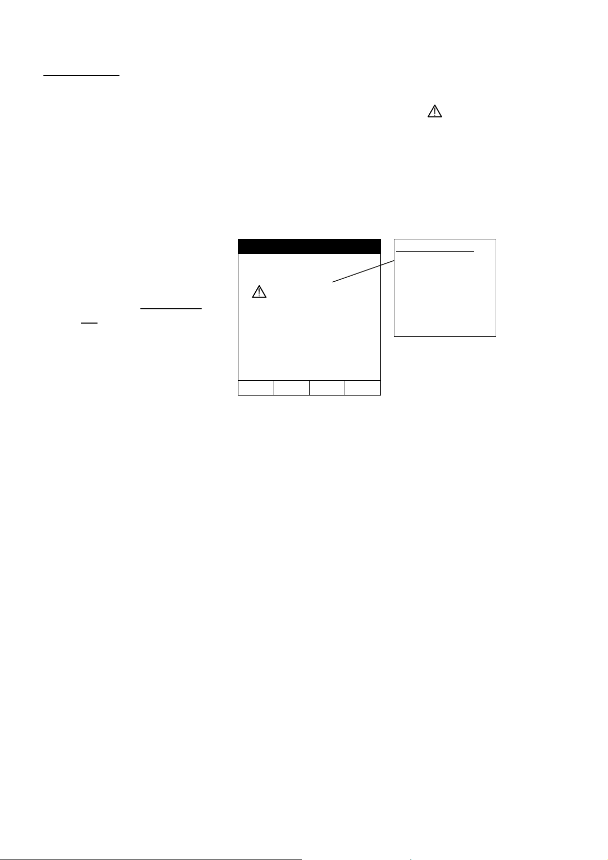
6.1.1. Calibrating the test leads ("CAL" Mode)
1. Connect the Red and Black test leads to B1 and B4 input terminals
respectively.
B2 B3 B4
B1
Connection of the test leads during calibration procedure.
2. Short-circuit the measuring cable ends making sure that the conductive parts of the
croc clips make a good contact to each other (see previous picture).
3. Press the F2 key. The instrument carries out the calibration.
WARNING
Never disconnect the test leads when the message "MEASURING" is
displayed.
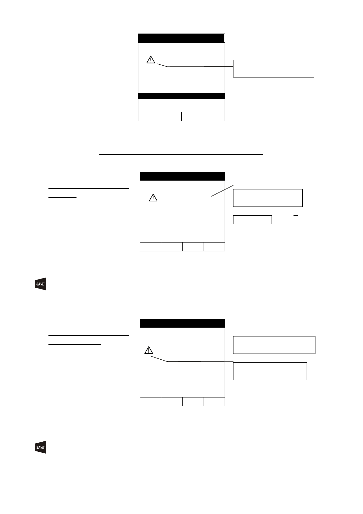
LOWΩ05.06.01
----Ω
R+ R-
----Ω----Ω
---mA ---mA
AUTO 0.11Ω
FUNC CAL
A numerical value
in this field means
that the instrument
has been
calibrated; this
value remains on
the display for
any further
measurement
even though the
unit is switched off
and on again.
4. At the end of the test, the result is stored and used as an OFFSET (that is to
say that it is subtracted from any continuity test carried out) for all the
subsequent measurements.
Note: The instrument performs the calibration only if the resistance of the test leads is
lower than 5Ω.
BLACK
RED
_____________________________________________________________MARVR2250
15
TEST LEADS Before each measurement always make sure that the calibration is
applicable to the test leads in use. During a continuity test, if the resistance
value free of calibration (that is the resistance value is less than the
calibration offset value) is negative, the symbol is displayed. The
calibration resistance value stored in the instrument memory is not
applicable to the test leads in use; therefore a new calibration must be
performed.
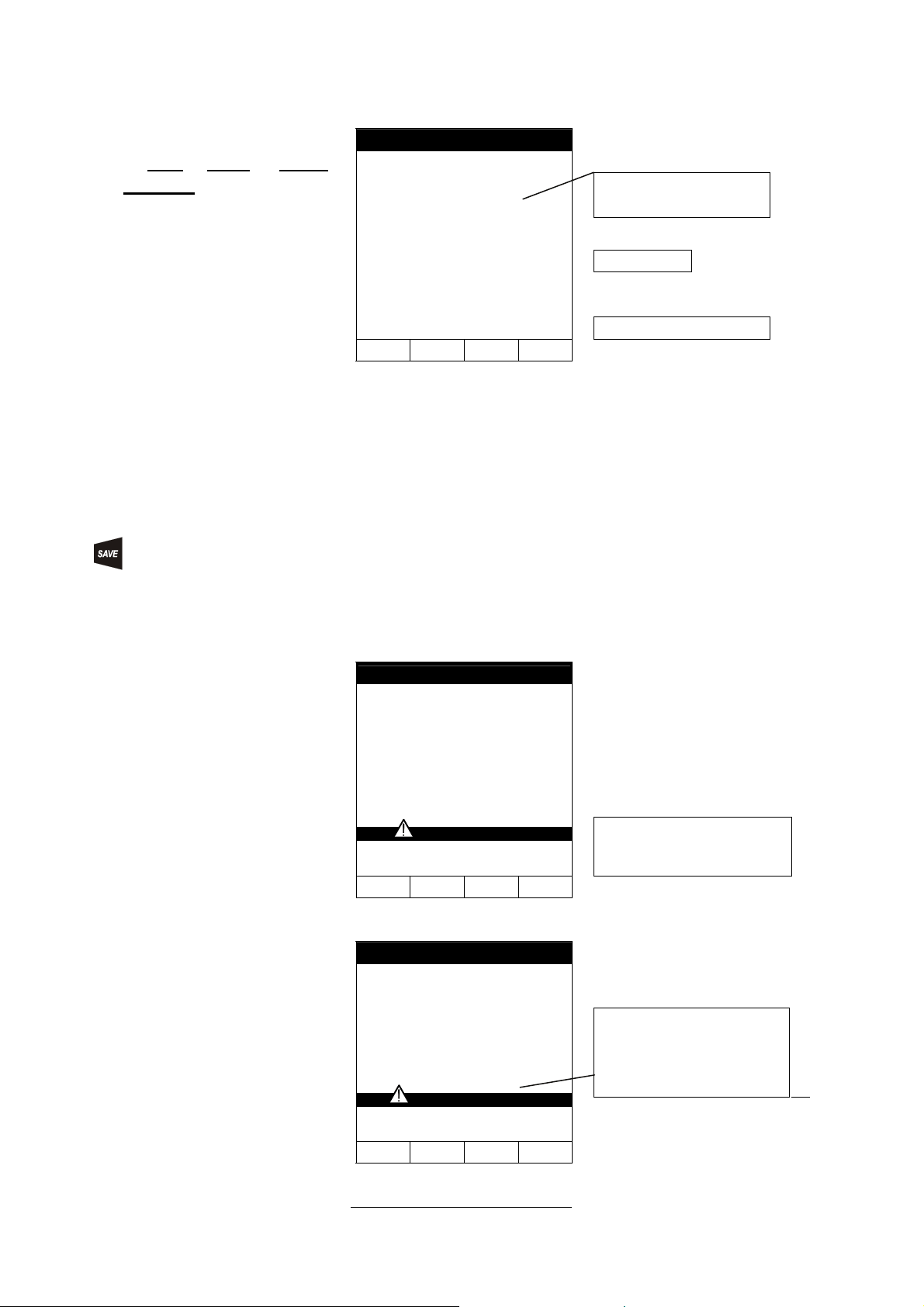
6.1.1.1. Procedure to reset test leads calibration parameters
LOWΩ05.06.01
Message >99.9Ω:
This means that the
instrument has
detected a resistance
higher than 5Ω,
therefore resetting
the calibration
parameters
>99.9Ω
R+ R-
----Ω----Ω
---mA ---mA
AUTO 0.11Ω
FUNC CAL
To remove a stored
calibration you must
perform the calibration
procedure with a
resistance higher than
5Ω(for example, with
disconnnected test leads

_____________________________________________________________MARVR2250
16
6.1.2. Measurement Procedure
1. Select the desired mode by means of the F1 key.
2. Connect the Red and Black test leads to B1 and B4 input terminals respectively
B2 B3 B4B1
Connection of the test leads during LOW Ωtest.
3. If the cables supplied with the instrument are not long enough for the measurement
you may extend the black cable.
4. Short-circuit the test leads making sure that the conductive parts of the croc clips
make a good contact with each other. Press the START key. If the display does
not show 0.00Ω, repeat the test lead calibration (see paragraph 6.1.1).
5. Connect the instrument terminals to the ends of the conductor under test (see
previous picture).
6. If the mode "RT+" or "RT-" was selected use the F3, F4 keys to set the
duration of the test.
7. Press the START key. The instrument will execute the measurement. In RT+/RT-
(Timer mode) you can press START key again if you want to stop the test before the
duration set has expired.
WARNING
Never disconnect the test leads when the message "MEASURING" is
displayed.
6.1.3. Results of "AUTO" mode
LOWΩ05.06.01
Average resistance
value (Ravg)
1.05Ω
R+ R-
1.07Ω1.03Ω
219mA 219mA
AUTO 0.11Ω
Resistance values
and corresponding
test current when the
polarities of test
leads swapped.
FUNC CAL
A
t the end of the test, if
the average resistance
value Ravg is lower
than 5Ω,the instrument
emits a double sound
signal indicating the
positive outcome of
the test and displays a
screen similar to this.
The displayed result can be stored pressing the SAVE key twice
(see paragraph 8.1).
START
STOP
BLACK
RED
Main Earth Connector
P-E Conducto
r
_____________________________________________________________MARVR2250
17
6.1.4. Results of "RT+" and "RT-" modes
LOWΩ05.06.01
Max resistance value of
R+ or R-.
Test current
1.07Ω
219mA
RT+ 0.11ΩTIME: 10s Duration of the test
FUNC CAL ↑↓
If the resistance value
of RT+ or RT+ is lower
than 5Ω, the instrument
emits a double sound
signal indicating the
positive outcome of
the test and displays a
screen similar this.
Note: We recommend that crocodile clips are used to achieve a good contact with the
conductor under test. In this test the instrument gives as a final result the maximum
measured value of R+ or R-, and using test leads instead of crocodile clips could give
an incorrect result due to bad contact between the test leads and conductor under
test.
The displayed result can be stored pressing the SAVE key twice
(see paragraph 8.1).
6.1.5. "AUTO", RT+", "RT-" faulty cases
LOWΩ05.06.01
Disconnect the External
If the instrument detects
the external power
supply adapter
connected the
instrument will display a
screen similar to this
-.- -Ω
R+ R-
---Ω---Ω
---mA ---mA
REMOVE POWER
AUTO 0.11Ω Power Supply Adapter
FUNC CAL
LOWΩ05.06.01
ATTENTION: the test was
not performed because of
voltage at the terminals
-.- -Ω
R+ R-
-.--Ω-.--Ω
---mA ---mA
VOLT IN INPUT
AUTO 0.11Ω
FUNC CAL
If the terminal voltage is
higher than 15V, the
instrument does not
carry out the test, and
displays a screen similar
to this for 5 seconds.
_____________________________________________________________MARVR2250
18
LOWΩ05.06.01
ATTENTION:
RCALIBRATION >RMEASURED
0.00Ω
R+ R-
0.00Ω0.00Ω
219mA 219mA
CAL > RES
AUTO 0.11Ω
FUNC CAL
In case that:
RCALIBRATION>RMEASURED
the instrument displays
the screen alongside.
THE PREVIOUS RESULTS CANNOT BE SAVED.
LOWΩ05.06.01
Resistance value higher
than 5Ω
Test current
5.17Ω
R+ R-
5.17Ω5.17Ω
209mA 209mA
AUTO 0.11Ω
FUNC CAL
If the value of
resistance is higher
than 5Ω(but lower than
99.9Ω)the instrument
emits a long sound
signal and displays a
screen similar to this.
The displayed result can be stored pressing the SAVE key twice
(see paragraph 8.1).
LOWΩ05.06.01
Resistance value higher than
99.9Ω
ATTENTION: Value of
resistance is out of range
>99.9Ω
R+ R-
>99.9Ω>99.9Ω
---mA ---mA
AUTO 0.11Ω
FUNC CAL
If the value of the
resistance is higher
than 99.9Ωthe
instrument emits a long
sound signal and
displays a screen similar
to this.
The displayed result can be stored pressing the SAVE key twice
(see paragraph 8.1).

_____________________________________________________________MARVR2250
19
6.2. MΩ: INSULATION RESISTANCE MEASUREMENT WITH 50V, 100V, 250V,
500V, 1000V TEST VOLTAGE
These measurements comply with IEC 61557-2 and VDE 0413 part 1.
WARNING
Before carrying out the insulation test, make sure that the circuit under test
is not energised and all the loads are disconnected.
Turn the switch to the MΩposition.
The key F1 selects one of the following measuring modes:
Mode "MAN" (Manual mode). Minimum test time of 5 secs, or for as long
as the start key is pressed. This is the recommended test.
Mode "TMR" (Timer mode: test duration depends on the selected interval
from 10 to 999 seconds). This test can be used if a minimum measuring
time is required.
6.2.1. Measurement Procedure
1. Select the desired mode by means of the F1 key.
2. Connect the test leads to the instrument input terminals B1 and B4 respectively,
M
B2 B3 B4B1
I1
Example: insulation measurement between phase L1 and earth in a 3 PHASE electrical installation
using test leads.
3. If the cables supplied with the instrument are not long enough for the measurement
you may extend the black cable.
4. Connect the instrument terminals to the object which is to be submitted to the
insulation test after de-energizing the circuit under test and all loads
(see above).
5. By using F2, select the test voltage suitable for the type of test to be carried out
(see Table 1). The values that can be selected are:
•50V (test on telecommunication system)
•100V
•250V
•500V
•1000V
BLACK
RED
Table of contents
Other Thorne & Derrick Measuring Instrument manuals


