Thorne & Derrick Rotronic HygroClip HC2-Ix25 User manual
ROTRONIC
HygroClip
®
HC2-Ix25
Mit dem ROTRONIC HygroClip HC2-Ix25 haben Sie ein Spitzenprodukt erwor-
ben, das den gängigen Normen entspricht. Bei Beachtung der unten aufge-
führten Bedienungshinweise funktioniert der HygroClip über Jahre perfekt.
Einsatzbereich Feuchte: 0...99 %rF
Einsatzbereich Temperatur:
HC2-IP25/HC2-IS25/HC2-IT25: -40...85 °C
Standard Messbereiche:
Alle Parameter sind frei skalierbar
Feuchte: 0...100 %rF = 0...1 V
Temperatur: -40…60 °C = 0...1 V
Tau-/Frostpunkt: Einstellbar via PC&HW4 Software
Technische Daten:
Versorgung: 3,2...5 VDC ± 0 % / ca. 4 mA
Justiert bei 3.3 VDC. Bie anderen
Versorgungsspannungen muss
der Fühler neu justiert werden
Ausgangsbürde: >10 kΩ
Kabellänge: Max. 5 m ohne Booster
Max. 100 m mit Booster Art. Nr.: AC3003
Schutzart: IP65 (ausser Sensorbereich)
Ausgänge: Analog: 2 x 0…1 VDC, UART Schnittstelle
Genauigkeit bei 23 °C: 0...90 %rF 1.5 %rF, 0.2 K
90...99 %rF 2.0 %rF, 0.2 K
Montage
Die Fühler sind dafür vorgesehen in eine Schaltwand oder Paneele
eingebaut zu werden.
Maximale Wandstärke: 9 mm
Einbauöffnung: ø 25 mm (25…27mm)
Die Schutzkappe dient zum Transportschutz und zur Abdeckung des
Messraumes im Falle einer Reinigung oder Desinfektionsmassnahme der
Schaltwand oder Paneele. Für die Inbetriebnahme und Feuchtemessung
des Fühlers ist die Schutzkappe zu entfernen.
ROTRONIC
HygroClip
®
HC2-Ix25
Your ROTRONIC HygroClip HC2-Ix25 is a leading-edge product that meets
all established standards. It will work perfectly for many years if you follow
the operating guidelines below.
Operating range humidity: 0...99 %rh
Operating range temperature:
HC2-IP25/HC2-IS25/HC2-IT25: -40...85 °C
Standard measuring ranges:
All parameters are freely scaleable
Humidity: 0...100 %rh = 0...1 V
Temperature: -40…60 °C = 0...1 V
Dew-/frost point: Selectable by PC using HW4 software
Technical data:
Supply: 3.2...5 VDC ± 0 % / approx. 4 mA
Adjustet at 3.3 VDC. The probe needs to
be adjusted when the probe is powered
on a different voltage than 3.3 VDC.
Load: >10 kΩ
Cable length: Max. 5 m without booster
Max. 100 m with booster item no.: AC3003
Protection rating: IP65 (except sensor area)
Outputs: Analog: 2 x 0…1 VDC, UART interface
Precision at 23 °C: 0...90 %rh 1.5 %rh, 0.2 K
90...99 %rh 2.0 %rh, 0.2 K
Mounting
The probes are intended for being built into walls or panels.
Maximum wall thickness: 9 mm
Cutout: ø 25 mm (25…27mm)
The protection cap is used for transport protection and coverage of the
probe in case of cleaning. For commissioning and measurement the
protection cap is removed.
Anschluss
Setzen Sie den HygroClip auf den Gegenstecker des Messumformers oder
des Anschlusskabels. Achten Sie darauf, dass die Sperrnocken richtig
ausgerichtet sind. Ziehen Sie die Rändelmutter von Hand fest.
Justierung / Kalibrierung
Die Fühler sind ab Werk justiert. Wir empfehlen je nach Einsatz eine
Kalibrierung nach ca. einem Jahr. Dies kann vor Ort mit ROTRONIC SCS
Feuchte-Standards durch Sie erfolgen. Die Handhabung entnehmen Sie
der den Feuchtestandards beiliegenden Anleitung. Betreffend Justierung
kontaktieren Sie ROTRONIC oder unsere Vertretung.
Weitere Information unter www.rotronic.com
Connection
Plug the HygroClip on the mating connector of the transmitter or connec-
tion cable. Make sure that the catches are aligned correctly. Tighten the
knurled nut by hand.
Adjustment / Calibration
The probes are adjusted in our factory before delivery. We recommend
calibration after about one year depending on use. You can do this yourself
on-site with the ROTRONIC SCS humidity standards. Please refer to the
instructions included with the humidity standards. Contact ROTRONIC or
our representatives concerning adjustment.
Further information can be obtained at www.rotronic.com
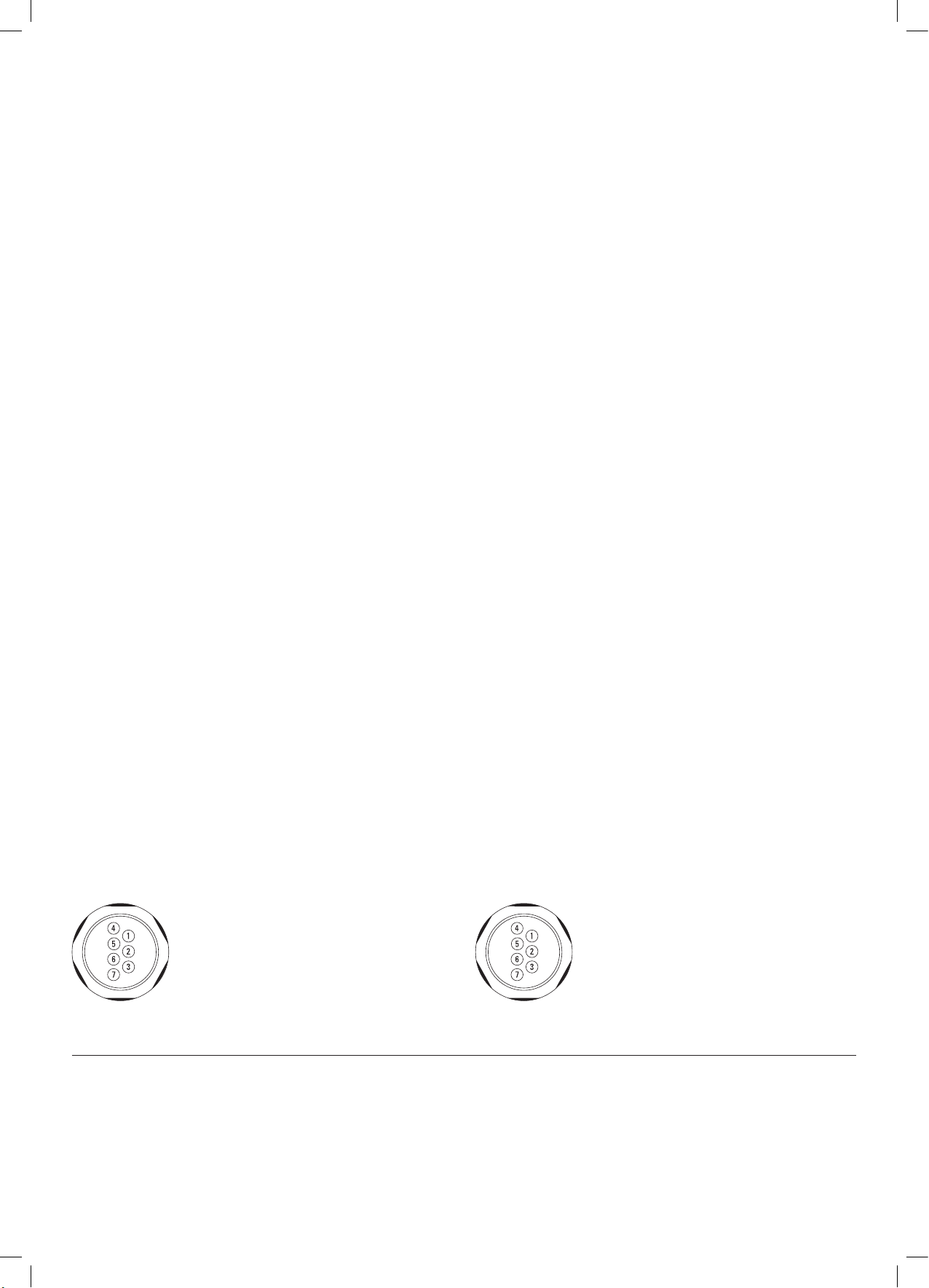
Electrical connections:Elektrische Anschlüsse: 1green V+
2gray GND (digital and power)
3red RXD (UART)
4blue TXD (UART)
5white Analog signal, humidity
(0...100%rh=0...1V)
6brown Analog signal, temperature
(-40...60°C=0...1V)
7yellow AGND (analog ground)
1grün V+
2grau GND (Digital und Versorgung)
3rot RXD (UART)
4blau TXD (UART)
5weiss Analogsignal Feuchte
(0...100%rF=0...1V)
6braun Analogsignal Temperatur
(-40...60°C=0...1V)
7gelb AGND (analog ground)
12.0980.0001_HC2-Ix25_Vitrinenfühler.indd 1 02.12.2011 14:25:04
Tel:
+44
(0)191 490 1547
Fax: +44 (0)191 477 5371
Email: northernsales@thorneandderrick.co.uk
Website: www.heattracing.co.uk
www.thorneanderrick.co.uk

ROTRONIC
HygroClip
®
HC2-Ix25
En achetant le ROTRONIC HygroClip HC2-Ix25, vous avez acquis un pro-
duit de pointe répondant aux normes courantes. L’HygroClip fonctionnera
parfaitement pendant de longues années si vous observez les instructions
d’emploi ci-dessous.
Gamme d’utilisation (humidité): 0...99 %HR
Gamme d’utilisation (température):
HC2-IP25/HC2-IS25/HC2-IT25: -40...85 °C
Gammes de mesure standard:
Les paramètres sont modifiables librement
Humidité: 0...100 %HR = 0...1 V
Température: -40...60 °C = 0...1 V
Point de rosée/de gel: Au choix, par PC et logiciel Hw4
Caractéristiques techniques:
Alimentation: 3,2...5 VDC ± 0 % / env. 4 mA
Ajusté à 3,3 VDC. Apres le changement
du tension d'alimentation le capteur
doit être Re-ajusté.
Charge de sortie: >10 kΩ
Longueur de câble: Max.: 5 m sans amplificateur de signal
Max.:jusqu'à 100 m avec amplificateur
de signal (no. d’article AC3003)
Protection: IP65 (sauf zone d’élément sensible)
Sorties: Analogique: 2 x 0…1 VDC, interface UART
Précision à 23 °C: 0...90 %HR 1.5 %rF, 0.2 K
90...99 %HR 2.0 %rF, 0.2 K
Montage:
Les capteurs sont prévus pour incorporer dans des tableaux de commande
ou pour des panels.
Epaisseur de paroi maximum: 9mm
Diamètre de découpe: ø25 mm (25…27mm)
Le capuchon sert de protection lors du transport ou de couvercle lors du
nettoyage ou désinfection des tableaux de commandes ou des panels dans la
salle de mesure. Lors de la mise en route et lors de mesure d’humidité, il faut
retirer le capuchon de protection.
Raccordement
Placez l’HygroClip sur la contre-fiche du transmetteur de mesure ou du
câble de raccordement. Veillez à la bonne orientation des cames de
blocage. Serrez les écrous moletés à la main.
Ajustage / étalonnage
Les capteurs sont ajustés en usine. En fonction de l’utilisation, nous
recommandons un étalonnage après environ un an. Vous pouvez réali-
ser l’étalonnage vous-même sur place à l’aide des étalons d’humidité
ROTRONIC SCS. Pour l’utilisation, veuillez vous référer aux instructions
accompagnant les étalons d’humidité. Pour l’ajustage, contactez
ROTRONIC ou notre représentant. Vous trouverez de plus amples in-
formations sous www.rotronic.com
ROTRONIC
HygroClip
®
HC2-Ix25
Il Vostro ROTRONIC HygroClip HC2-Ix25 è un prodotto di qualità, realizzato
in conformità con le normative del settore. Seguendo le istruzioni il Vostro
HygroClip lavora al massimo delle prestazioni per anni.
Range operativo umidità: 0...99 %ur
Range operativo temperatura:
HC2-IP25/HC2-IS25/HC2-IT25: -40...85 °C
Range di misura standard:
I parametri sono scalabili
Umidità: 0...100 %ur = 0...1 V
Temperatura: -40...60 °C = 0...1 V
Punto di rugiada/di ghiacco: Configurabile con PC e software HW4
Dati tecnici:
Alimentazione: 3,2...5 VDC ± 0 % / ca. 4 mA
Regolato a 3,3 VDC. Cambiando la
tensione di alimentazione deve essere
regolato il sensore.
Carico in uscita: >10 kΩ
Lunghezza cavo: massima: 5 metri senza l’amplificatore
di segnale
massima: fino a 100 metri usando
l’amplificatore di segnale
(No. Articolo AC3003)
Protezione: IP65 (eccetto la sezione sensore)
Uscite: Analogica: 2 x 0…1 VDC, interfaccia UART
Precisione a 23 °C: 0...90 %ur 1.5 %rF, 0.2 K
90...99 %ur 2.0 %rF, 0.2 K
Montaggio:
I sensori sono previsti per l’installazione in un pannello di controllo.
Massimo spessore: 9 mm
Ritaglio: Ø 25 mm ( 25 ... 27mm)
Il cappuccio di protezione viene utilizzato per per il trasporto del sensore.
La protezione viene usata in caso di pulizia e disinfezione del panello di
controllo. Per la messa in funzione del sensore di umidità, il cappuccio
protettivo deve essere rimosso.
Collegamento
Inserire l’HygroClip sul connettore relativo del trasmettitore o del cavo di
allacciamento. Controllare che i nottolini di blocco siano correttamente
posizionati. Serrare a mano i dadi zigrinati.
Regolazione / calibrazione
Le sonde sono regolate in fabbrica. Raccomandiamo di eseguire dopo circa
un anno una nuova calibrazione, a seconda dell’uso. Questo intervento
può essere eseguito personalmente utilizzando gli standard di umidità
ROTRONIC SCS. Per l’utilizzo, si prega di fare riferimento alle istruzioni
allegate agli standard di umidità. Contattare ROTRONIC o i rappresentanti
locali per eventuali consigli sulla procedura di calibrazione.
Ulteriori informazioni all’indirizzo www.rotronic.com
Connessioni elettriche:Raccordements électriques: 1verde V+
2grigio GND (digitale e alimentazione)
3rosso RXD (UART)
4blu TXD (UART)
5bianco Segnale analogico umidità
(0...100%ur=0...1V)
6marrone Segnale analogico temperatura
(-40...60°C=0...1V)
7giallo AGND (massa segnali analogici)
1vert V+
2gris GND (numérique et alim.)
3rouge RXD (UART)
4bleu TXD (UART)
5blanc Signal analogique
HR (0...100%HR=0...1V)
6brun Signal analogique
°C (-40...60°C=0...1V)
7jaune AGND (analog ground)
12.0980.0001_HC2-Ix25_Vitrinenfühler.indd 2 02.12.2011 14:25:04
Tel:
+44
(0)191 490 1547
Fax: +44 (0)191 477 5371
Email: northernsales@thorneandderrick.co.uk
Website: www.heattracing.co.uk
www.thorneanderrick.co.uk
Other Thorne & Derrick Measuring Instrument manuals


Popular Measuring Instrument manuals by other brands

Keysight Technologies
Keysight Technologies U4205A user guide

HP
HP 4154A Operation and service manual

Nic
Nic EMP Gold+ instruction manual

TPM
TPM AMT506 manual

PCB Piezotronics
PCB Piezotronics IMI SENSORS HT624B01 Installation and operating manual

MICRO-EPSILON
MICRO-EPSILON interferoMETER IMS5400-DS Quick manual


Landis & Gyr
Landis & Gyr Cashpower Gemini PLC user guide

Sensitech
Sensitech TempTale GEO Placement instructions

Tecomec
Tecomec GEOline GeoLevel instruction manual

Eaton
Eaton IQ 100 series User & installation manual

SUKU
SUKU 3319 operating manual

Endress+Hauser
Endress+Hauser Hart Micropilot FMR60B operating instructions